RC Transmitter Setup
This section provides instructions on how to configure the FlySky FS-i6S RC transmitter that is included in the AVR drone kit.
Setup
The FlySky FS-i6S RC transmitter is a highly configurable radio controller with a touch
screen, supporting up to 10 control channels at the same time. In order to use it with
the AVR drone, some setup is required, both for the RC transmitter and for the FC. On
this page, we will go into detail on how to set up the RC transmitter so that it can be
used to safely control the drone.
The radio controller box should include a quick start guide. A more detailed user manual
for the radio controller is available for download below.
The following sections will cover numerous aspects of the transmitter configuration
required to fly your AVR drone.
1 - Basic Usage
Overview
To turn on the transmitter, press and hold the two power buttons on the front of the
device until the screen lights up. After you see the logo, you will be presented with
the home screen.
You might see a warning when you turn on the transmitter about switch positions. Just
follow the instructions provided on the screen to continue to the home screen.
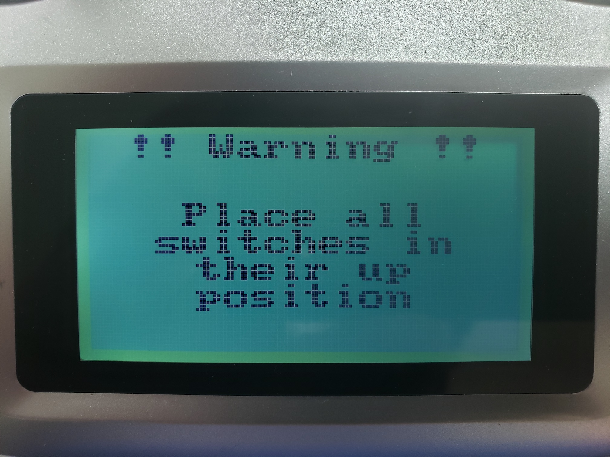
Make sure all switches are in the up position to continue to the home screen
The transmitter contains a touch screen used for displaying status info and for setup
purposes. The home screen has three different views. You can switch views by swiping
left and right, where the bottom indicator shows you which screen you are on (when you
start the transmitter, you see the center screen).
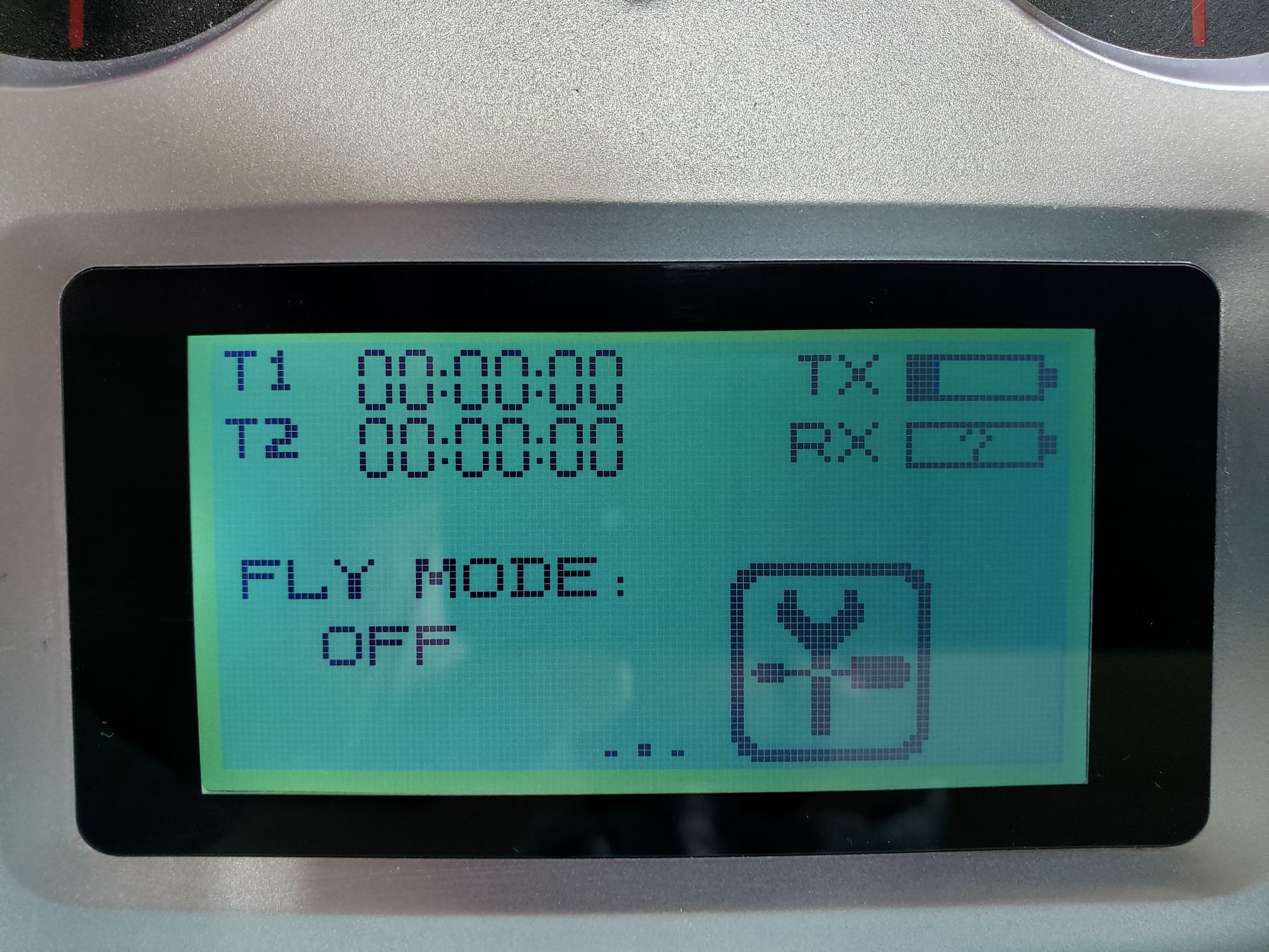
Home screen of transmitter
The left screen shows you the current value sent over all channels, while the right
screen shows information about sensors connected to the transmitter.
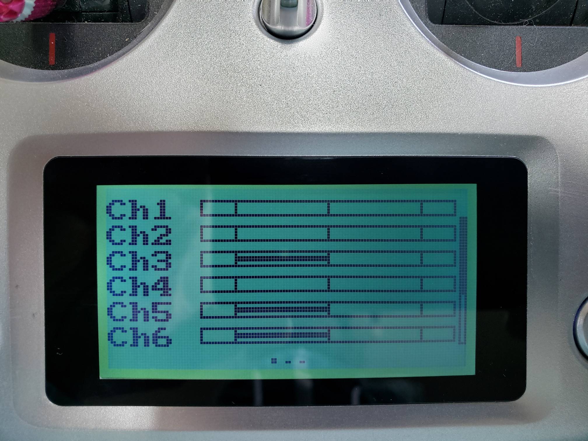
Left screen showing channel values
One thing that is helpful to gain an understanding of how your flight sticks map to
various channels is to swipe to the channel view and move your sticks around. You should
see the channel values update as you move the left and right sticks.
Screen Unlock
By default the transmitter settings will be locked which prevents you from accidentally
changing a setting. To unlock the screen press and hold the lock icon for 2 seconds.
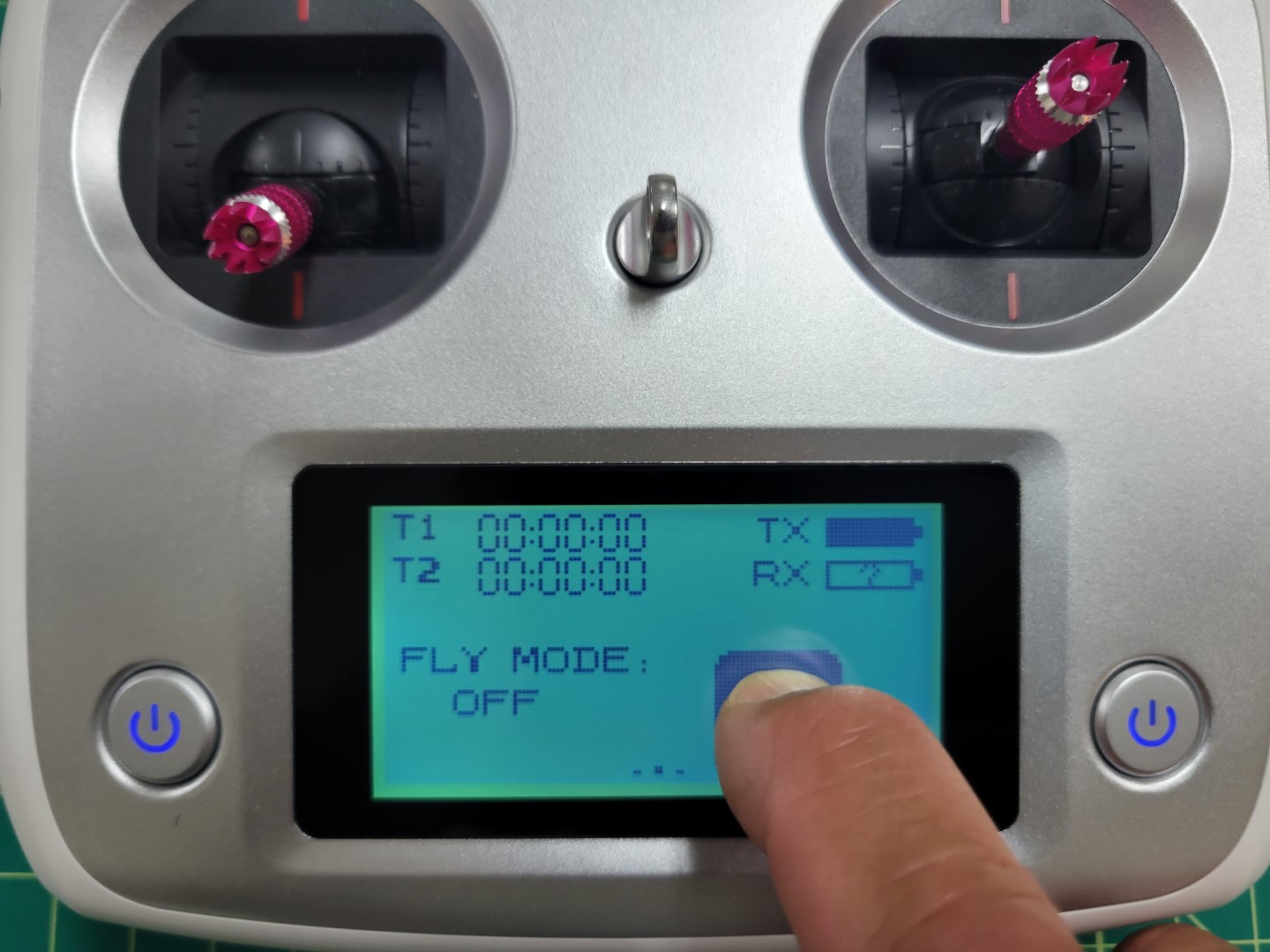
Press and hold 2 seconds to unlock
After unlocking you will see the settings icon with the wrench and screwdriver.
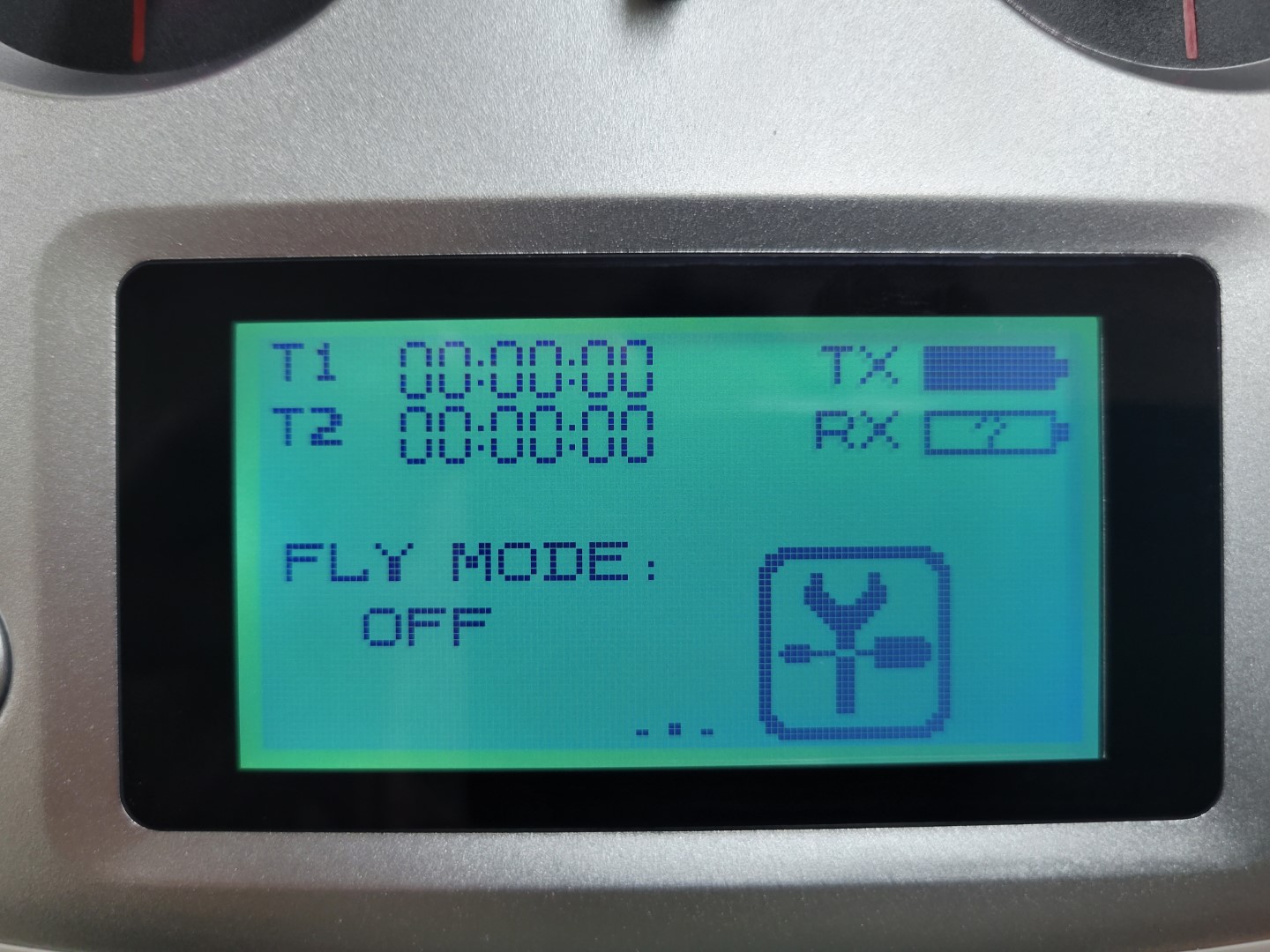
Settings icon on home screen
Configuration
Configuration is done by pressing the settings icon. The next screen has two different
views: the function view and the system view. The function view provides
options that change how the different sticks, buttons, and dials on the transmitter are
transformed to channel values.
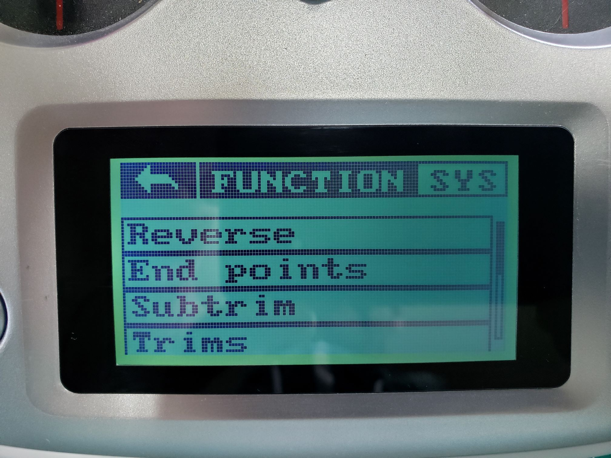
Function view
The system view provides options for setting up the transmitter itself. You can
change to the system view by pressing SYS.
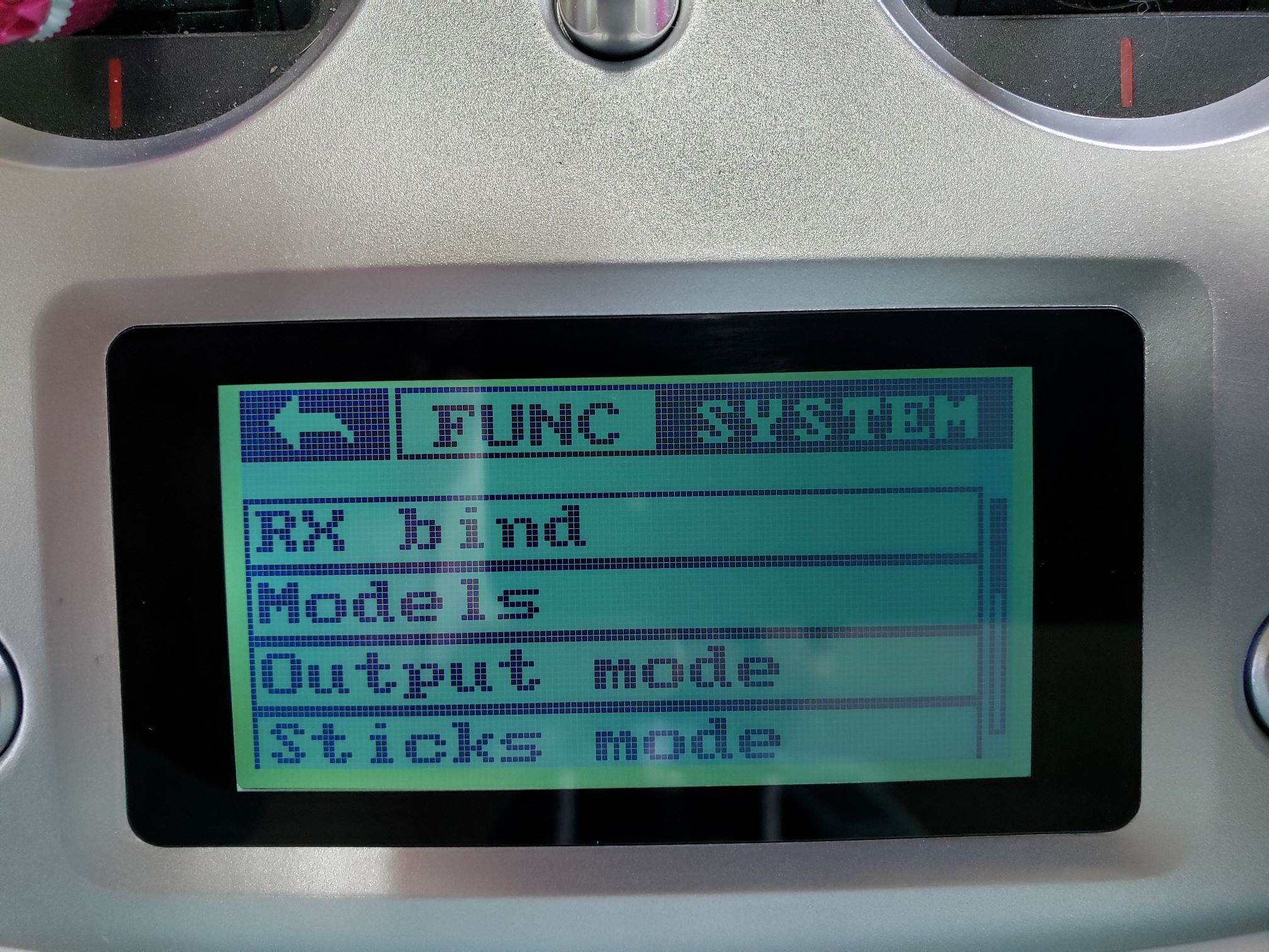
System view
Screen Lock Timeout
You will likely find that the screen lock timeout of 5 seconds is way too short. We
recommend changing this to 5 minutes while you’re becoming familiar with the
transmitter. You can do this by going to the system menu and selecting screen
lock.
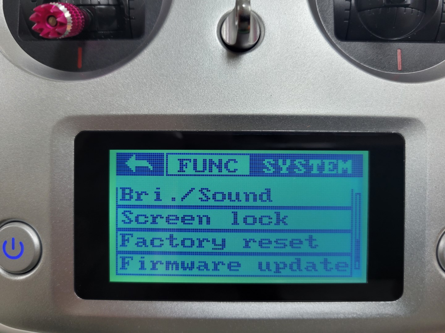
Screen lock in system menu
You have several screen lock timeout options. Select the one you’re most comfortable
with.
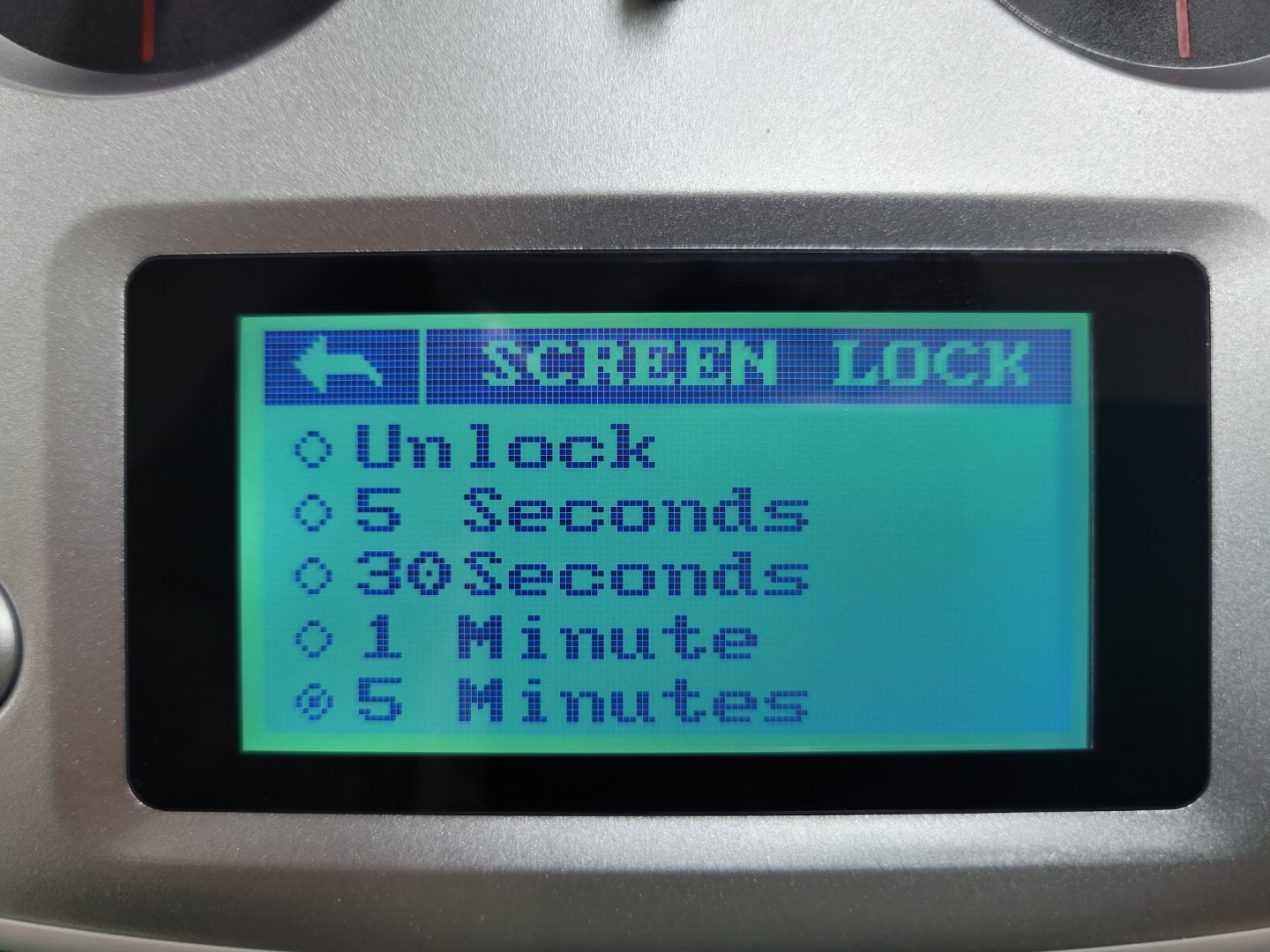
Screen lock timeout
2 - Binding the RC Receiver
The RC receiver module has already been installed on the drone in a previous step.
Please verify that it is correctly connected on both the receiver (RX) side and on the
FC side as shown in the photo below.

Aside from the physical connection we also need to establish a wireless connection
between the transmitter and the receiver. This wireless connection happens through a
process known as binding. Binding is what will allow us to control the AVR drone
with the transmitter and change flight modes, which will become important in the
competition.
Out of the box, the receiver and transmitter should be automatically bound to each
other. If this is the case, the RC transmitter display would look similar to the
picture below when both transmitter and receiver are turned on (receiving power). Please
note the RX battery bar. If this shows a question mark (while the receiver is getting
powered), then you will need to go through the binding process. We will cover that
shortly.

TX main screen showing RX connected
The TX battery bar shows the remaining capacity of the batteries in the transmitter.
However, the RX battery bar does NOT actually show the battery capacity of the
drone. It reports a reading of the voltage level (between 4.0 and 8.4 V) that is
provided to the receiver module by the FC, which should always be 5.0 V. In our case, it
is only useful for verifying that the transmitter and receiver module are communicating
with each other.
If your transmitter and receiver are already bound you can skip to the next section
labeled Setting the Output Mode. If the transmitter and receiver are not bound, you
can do it yourself. Make sure the FC is not powered by the battery or USB cable. Insert
the bind plug in the rightmost vertical slot (labeled B/VCC) on the receiver module, see
the picture below. You will find the bind plug in a small plastic bag in the transmitter
box. The cable that connects to the FC should remain as shown below.

Receiver with cable going to FC (black/red/white) and bind plug in B/VCC slot
Turn on the transmitter and go to the system view in the settings menu. Select
RX bind. It will wait for the receiver to be turned on in bind mode as well. You
should now power the FC, which will also power the RC receiver module. The easiest way
is to power the FC with a micro-USB cable. When power is provided, the receiver module
will go into bind mode because of the jumper wire. The binding procedure should be
finished automatically (you might not even notice).
Power everything down and you should now remove the bind plug from the receiver
module. It should not remain in the receiver as it will trigger the binding procedure
again every time the receiver module is powered. The next time you power up your
transmitter and receiver they will be communicating.
3 - Setting the Output Mode
In the world of drones and radio controllers, there are a lot of different protocols in
use. More information about these different protocols can be found
here. The FlySky
FS-iA6B receiver that was included with the FlySky FS-i6S transmitter supports PWM, PPM,
S.BUS, and i-BUS output, but the FC in the AVR kit only supports PPM and S.BUS. For the
AVR drone, it is recommended to use the S.BUS protocol since it is the most stable of
the two and supports more channels.
Configuring the RC receiver to output the S.BUS protocol can be done in the OUTPUT
MODE screen shown below. You can find the OUTPUT MODE screen on the system
view in the settings menu. Everything should be configured as shown in the picture.
This will set PPM and S.BUS as the output communication protocols, which will be
available on separate pins. The FC has already been connected to the pins on which S.BUS
output will be available.
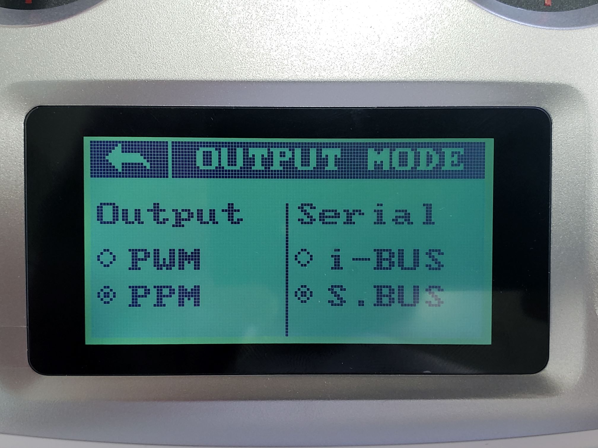
Output mode configured for PPM and S.BUS
Changes are automatically saved so you can tap on the back arrow to go to the previous
menu. If you power down your transmitter these settings will still be maintained.
4 - Setting Up Channels on the RC Transmitter
The receiver module supports up to 10 channels when using the S.BUS protocol. The first
4 channels are used for basic control with the transmitter sticks, leaving several free
channels which can be mapped to auxiliary control switches. Assigning switches, dials,
and buttons on the transmitter to channels can be done using the Aux. channels
option under the Function tab in the Settings menu.
These channels will be useful throughout AVR and will let us do things like toggle a
switch to change the current flight mode of the drone.
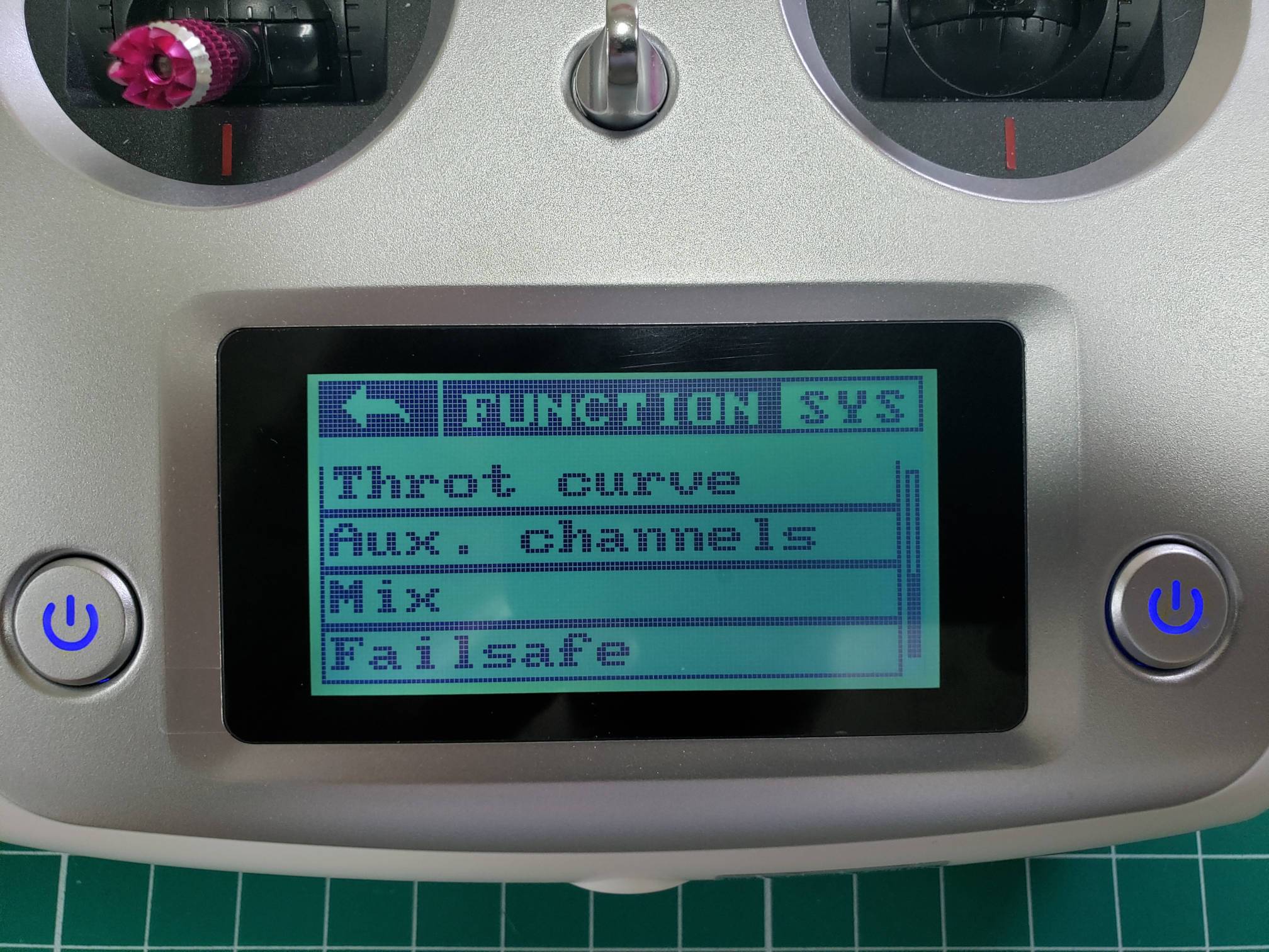
Auxiliary channels in Function menu
You can press the icon to change the kind of input (STX = stick, SWX = switch, VRX =
dial, KEY = button). Pressing the text label you can specify which exact input should be
mapped to the channel. It is also explained in
section 6.7 of the transmitter manual.
For the AVR drone, we provide a default channel setup which allows for maximum utility
of the available channels, which can be found below. In future references, we will
always use the channel setup as provided here.
| Channel | Switch |
|---|
| 5 | SWA |
| 6 | SWB |
| 7 | SWC |
| 8 | SWD |
The following steps will walk you through assigning Channel 5 to SWA. First, tap on
the big circle with the line through it.
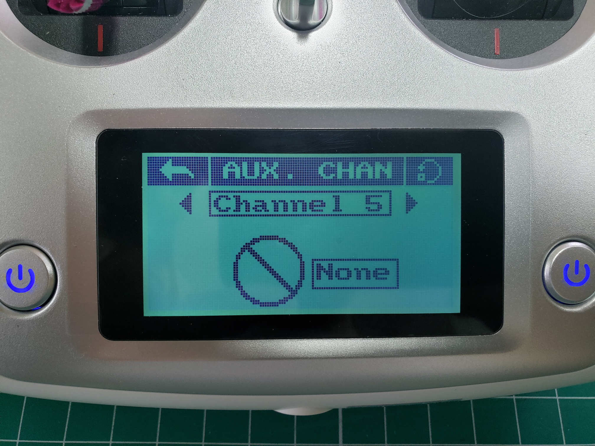
Channel 5 setup
The following screen allows you to assign CH5 to a switch. You will select SWx.
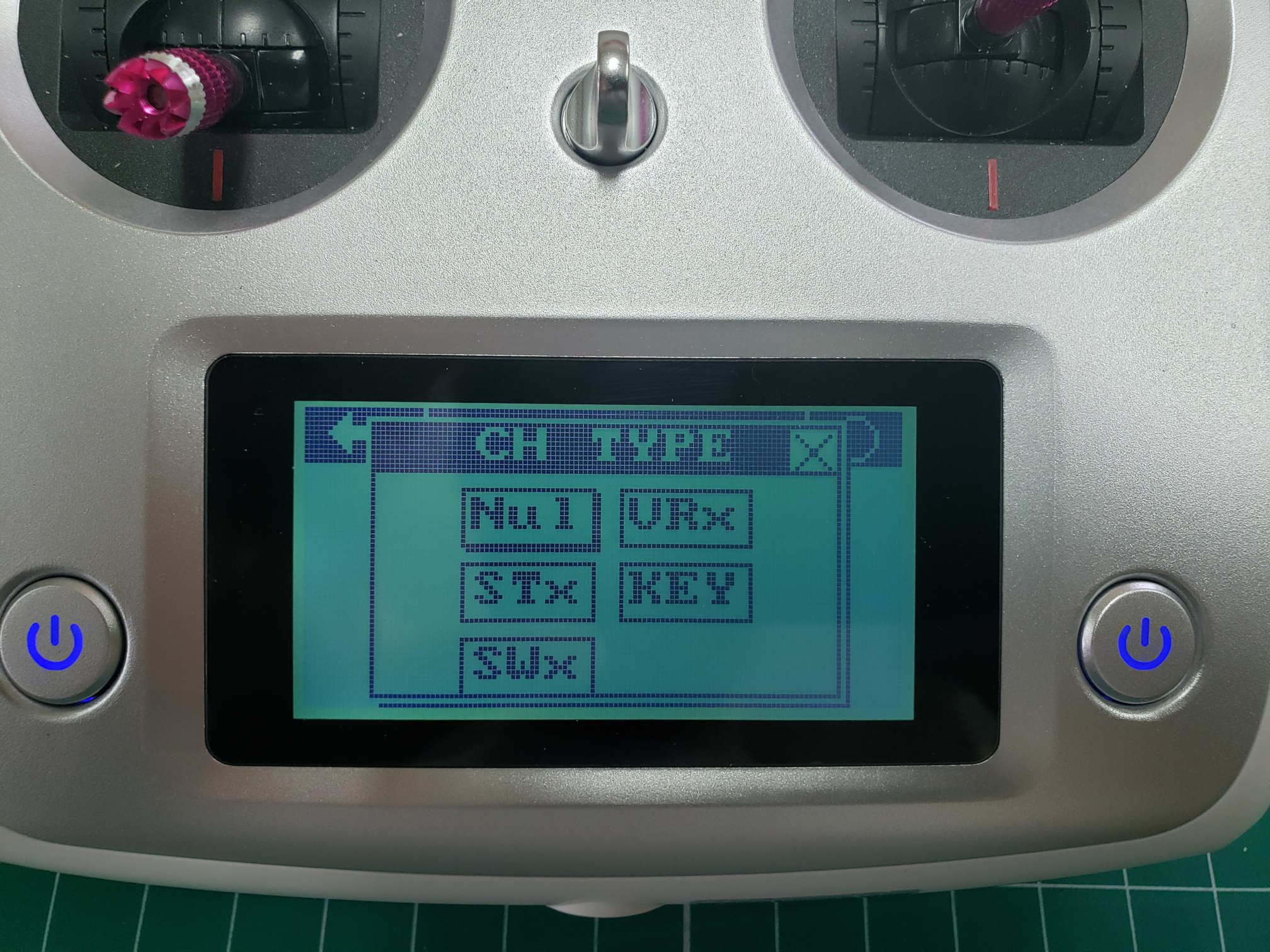
Assigning a channel to a switch
After selecting SWx you will be presented with a screen that lets you select one of
the following switches: SWA, SWB, SWC, or SWD for Channel 5. In this
case, we will select SWA.
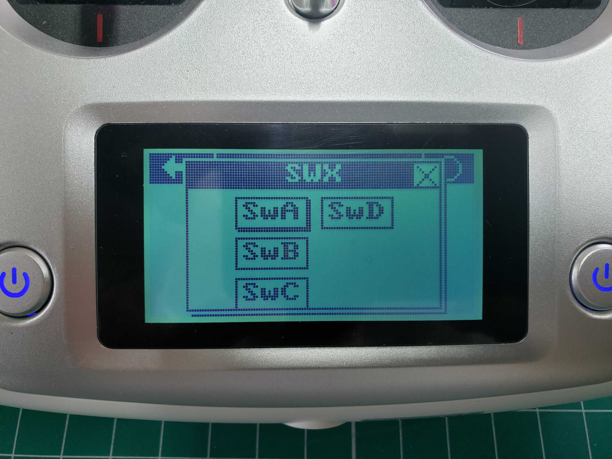
Select SWA for Channel 5
Repeat these steps for CH6, CH7, and CH8 based on the table above. After
completing the steps you can go back to the home screen and swipe right to see your
channel outputs. Swipe down to see CH5 - CH8 outputs. With all switches in their
default position (up) you should see the output as shown in the image below.
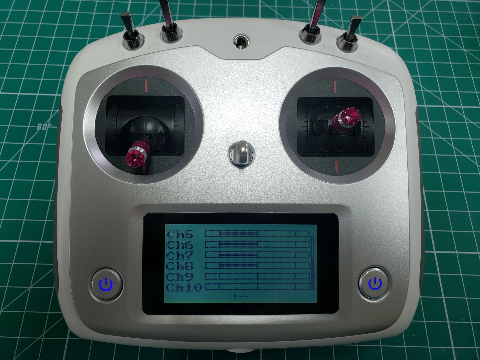
Default output for CH5-CH8 - all switches up
Now toggle all of your switches to the downward position. You should notice that the
output changes and should be identical to the image below.
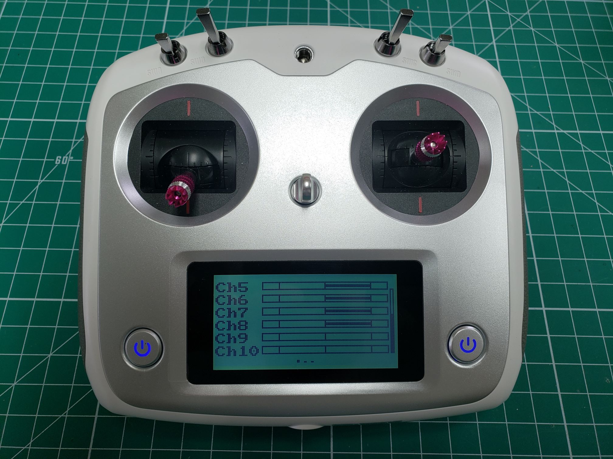
All switches toggled down
5 - Setting Up Failsafe
By default, when the RC receiver loses connection with the transmitter, the receiver
will continue sending the latest known stick position to the FC. While this can be
useful in some situations, it is very dangerous for flying drones: it can result in
fly-away situations whenever signal is lost! To change this, the failsafe option in
the function tab of the settings menu can be used. It allows us to set a desired value
for each channel to take on whenever the transmitter loses connection.
Warning
Setting up proper fail-safes is very
important for your own safety and the safety of your environment! Don’t neglect this,
and review your setup regularly!
While the FC should be able to detect signal loss and has different options to react in
such a situation, we also recommend a good failsafe setup on the RC transmitter, as a
last resort in case the FC does not detect the signal loss.
We recommend setting the failsafe options as follows in terms of stick and switch
positions. This will cause the drone to shut down its motors when the FC does not detect
the signal loss. This is the only viable option, it is not safe to keep the drone in
the air when we do not have any control over it.
We will later have a look at failsafe options in the FC configuration as well. For now,
we will set the RC transmitter failsafe to:
- Left stick (throttle/yaw) to the bottom and horizontally centered.
- Right stick (pitch/roll) both horizontally and vertically centered.
- Switches SWA, SWB, and SWC in the upward position, SWD in the downward
position.
This will set the throttle to zero and reset the yaw, roll, and pitch to neutral angles.
We will later assign functions to the switches, where the upper position will be the
default state. We will assign a kill switch function to SWD. With this failsafe
setting, the receiver will emulate the kill switch being flipped when it loses
connection, and ultimately disable the motors.
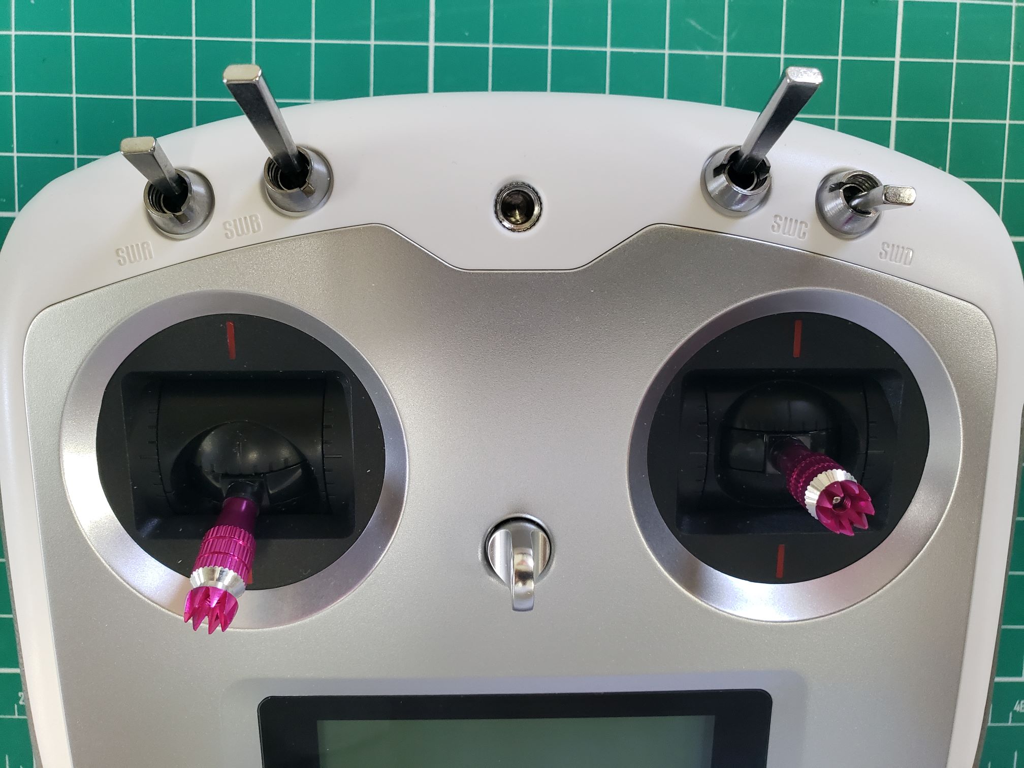
Default stick/switch positions with SWD kill switch enabled (toggled down)
Note
Channel values are normally represented by a
range of -100% to 100%. For example, the throttle stick (left stick vertical axis) is
assigned to CH3. When the throttle stick is all the way down CH3 is set to -100% and
when it is all the way up (maximum throttle) CH3 is set to +100%.
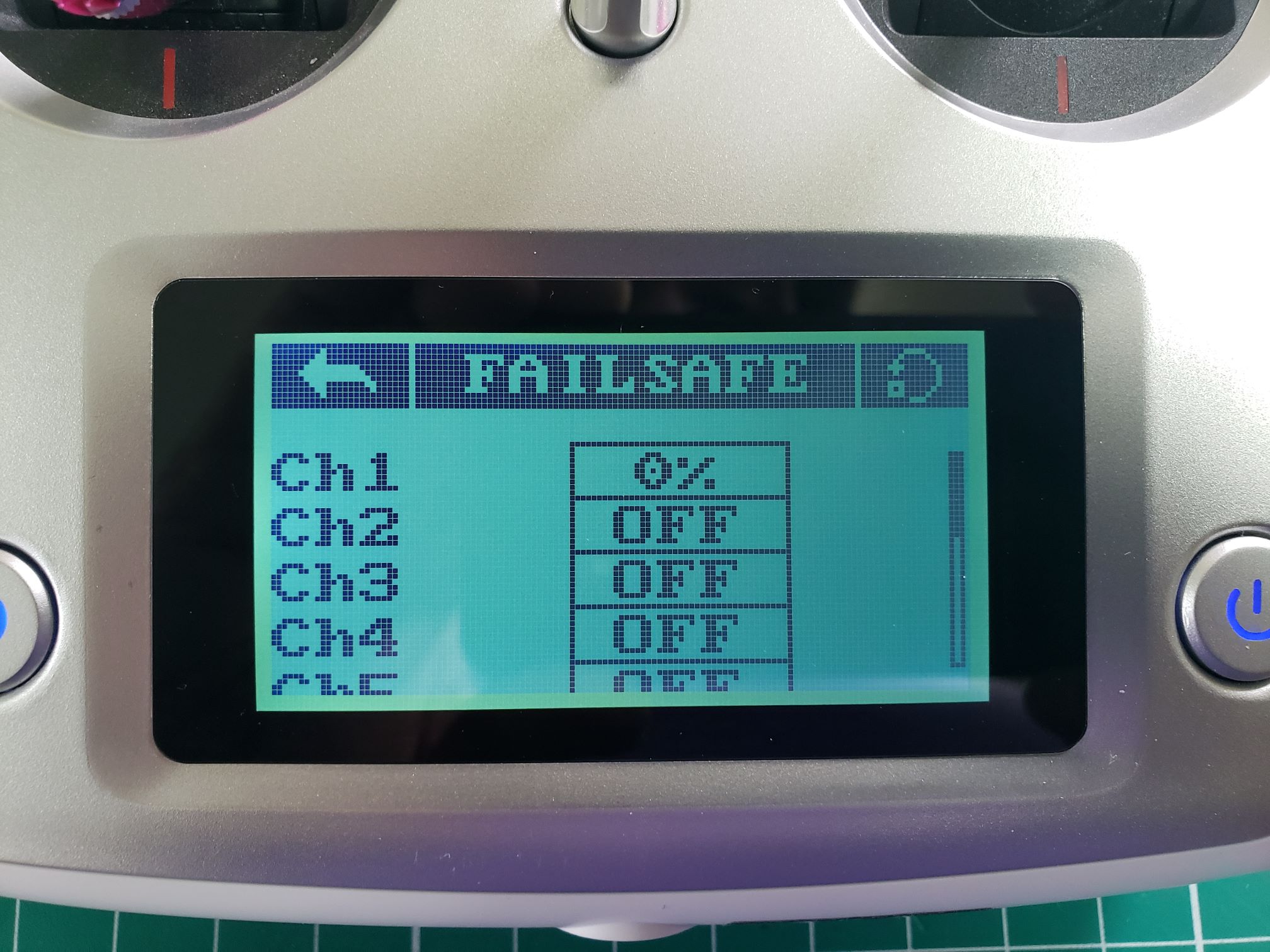
To begin setting up failsafe values, go to the Failsafe screen from the Function
screen in the Settings menu.
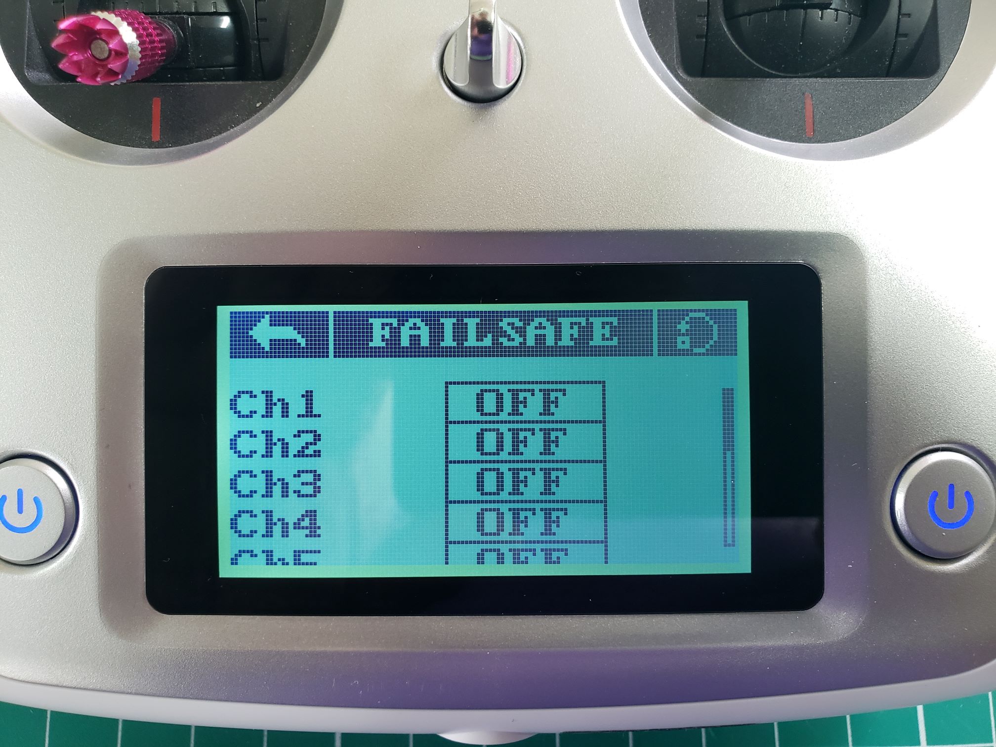
Default failsafe screen
To set up a failsafe for a channel, tap the Off button next to the channel.
In the screen that appears, tap the On button to enable the failsafe for that
channel.
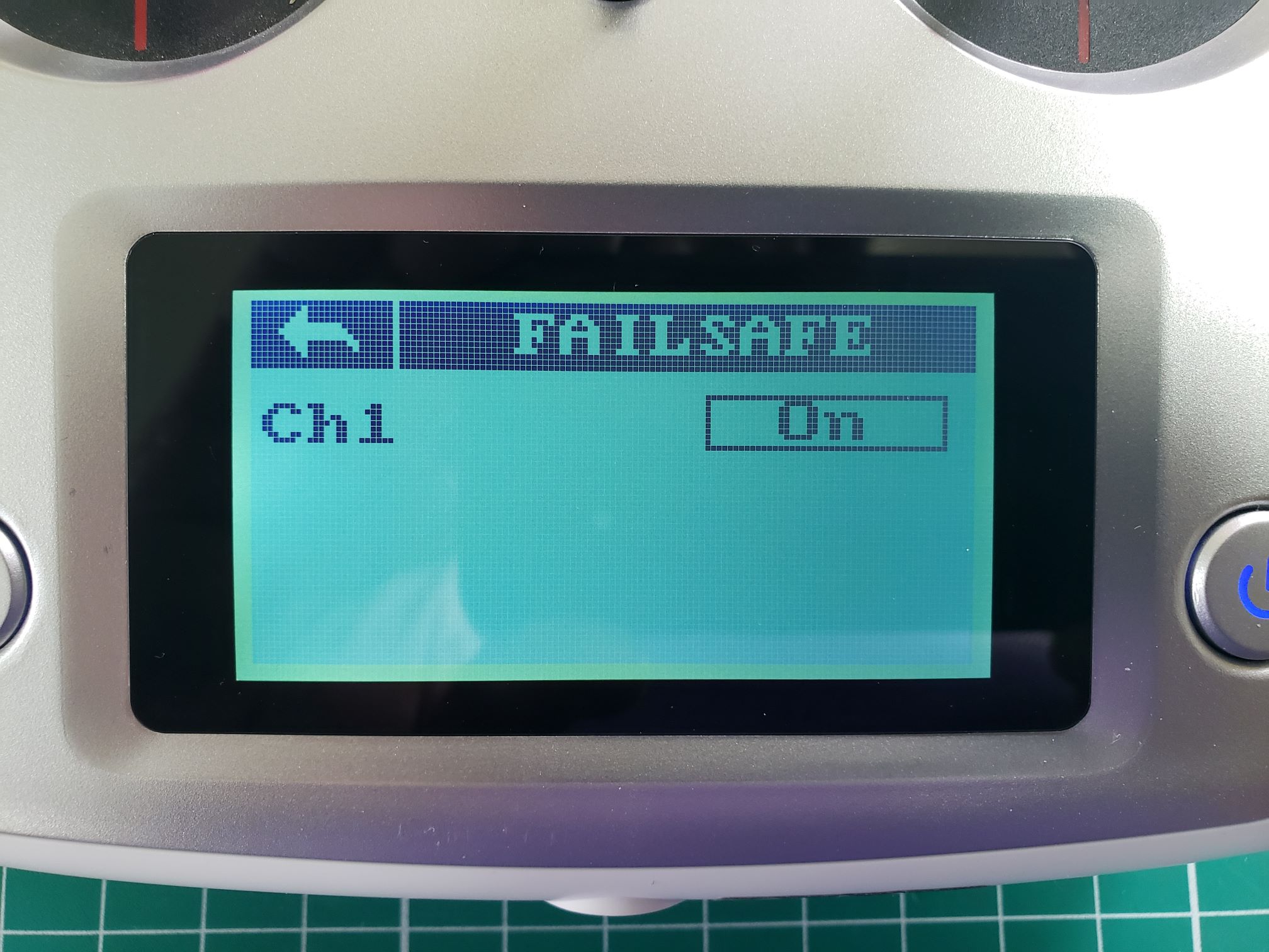
Setting up failsafe for CH1
Now make sure the stick/switch belonging to that channel is in the correct position. In
the case of CH1, which is assigned to the right stick, it will be horizontally and
vertically centered. Now tap the Setup button to save this position.
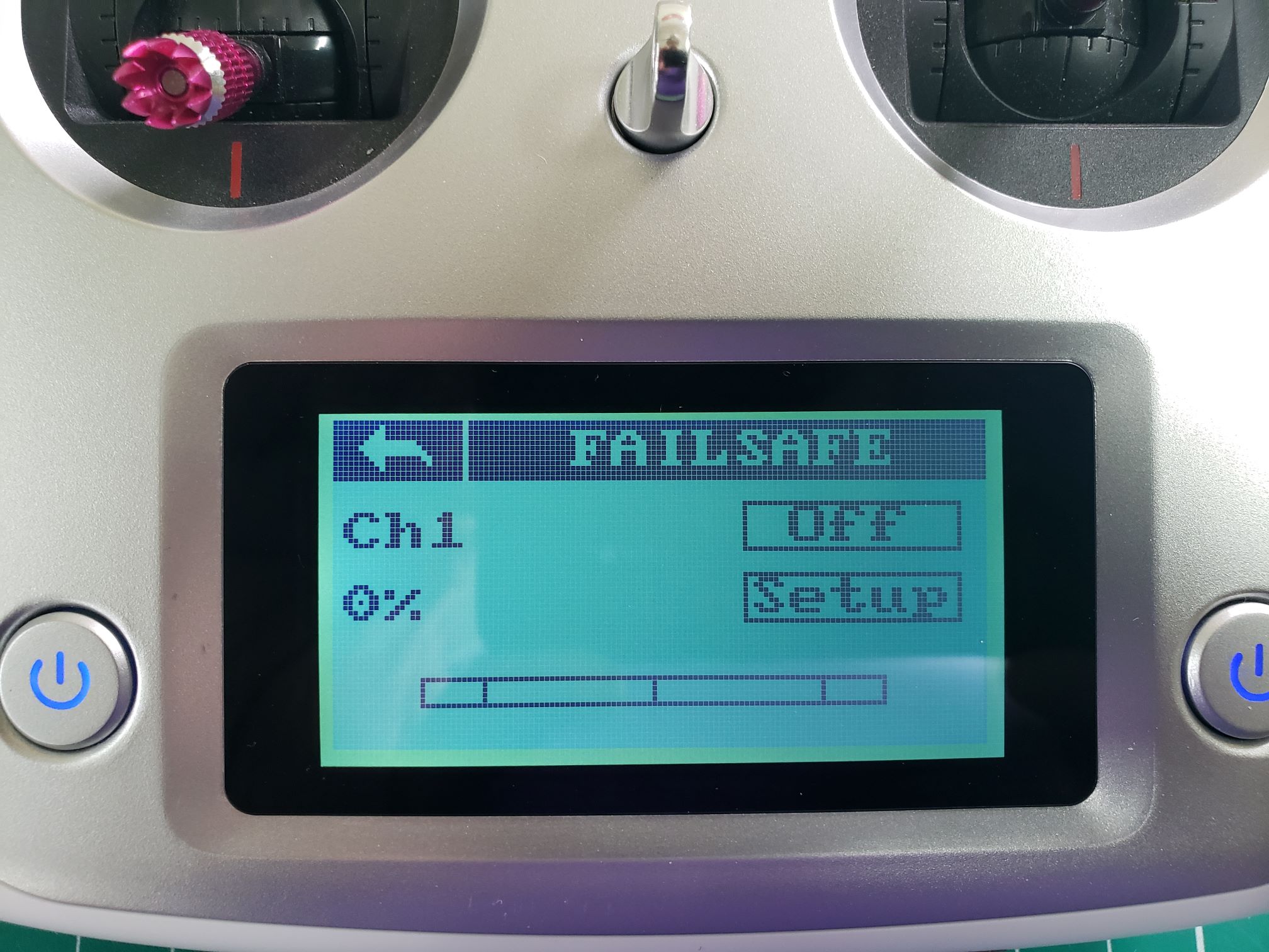
CH1 failsafe value set to 0%
After tapping Setup you will be taken to the main failsafe screen where you
can configure the failsafe for the rest of the channels.
CH1 failsafe value set to 0% (right stick centered)
Go ahead and complete the failsafe configuration for Channels 2, 3, and 4. When finished
you should see something identical to the image below.
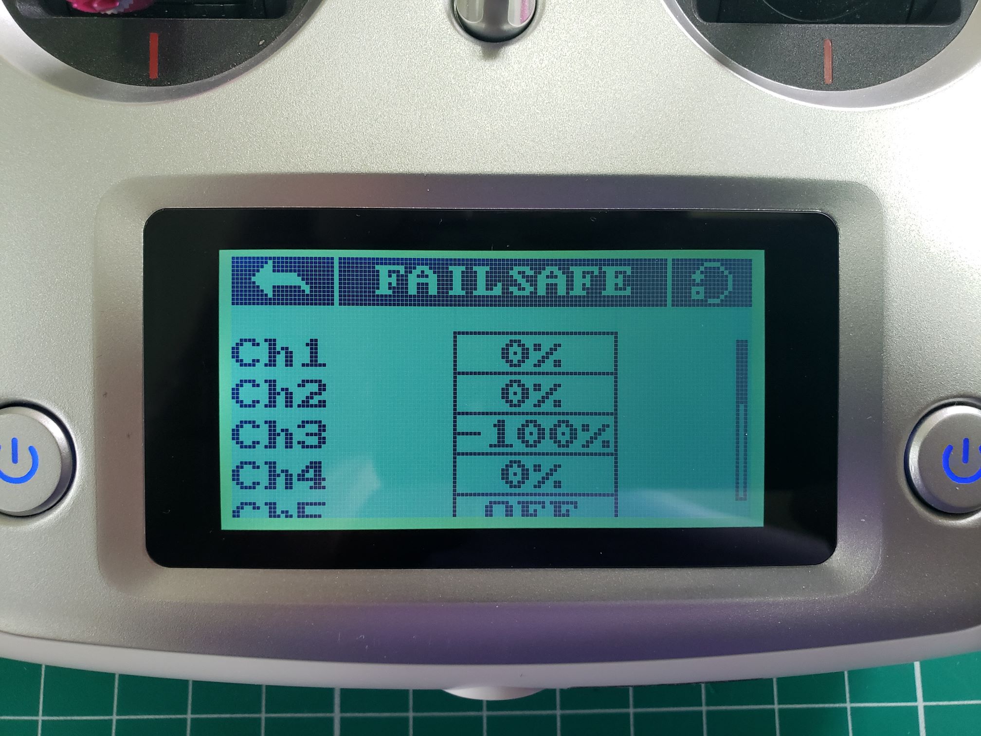
Failsafe configuration for Channels 1-4
We will now set up failsafe values for the switches we configured in the previous
section. Let’s run through an example of doing this for CH5, which is attached to
SWA. Make sure SWA, SWB, and SWC are in the up position and SWD is
in the down position.
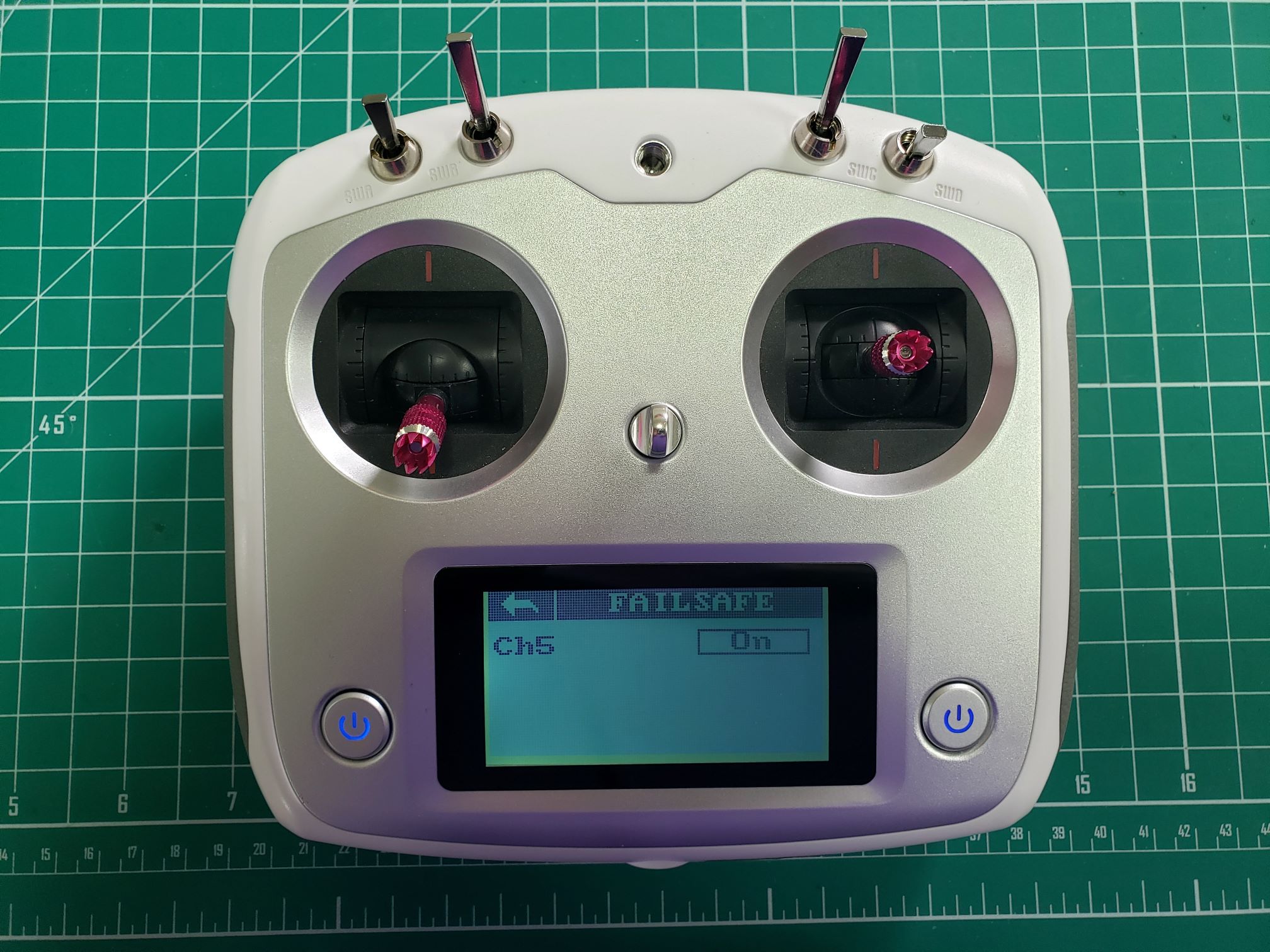
Setting up failsafe for CH5 attached to SWA
Tap On and then Setup for CH5. This will set a value of -100%
for CH5 (SWA up position) as shown below.
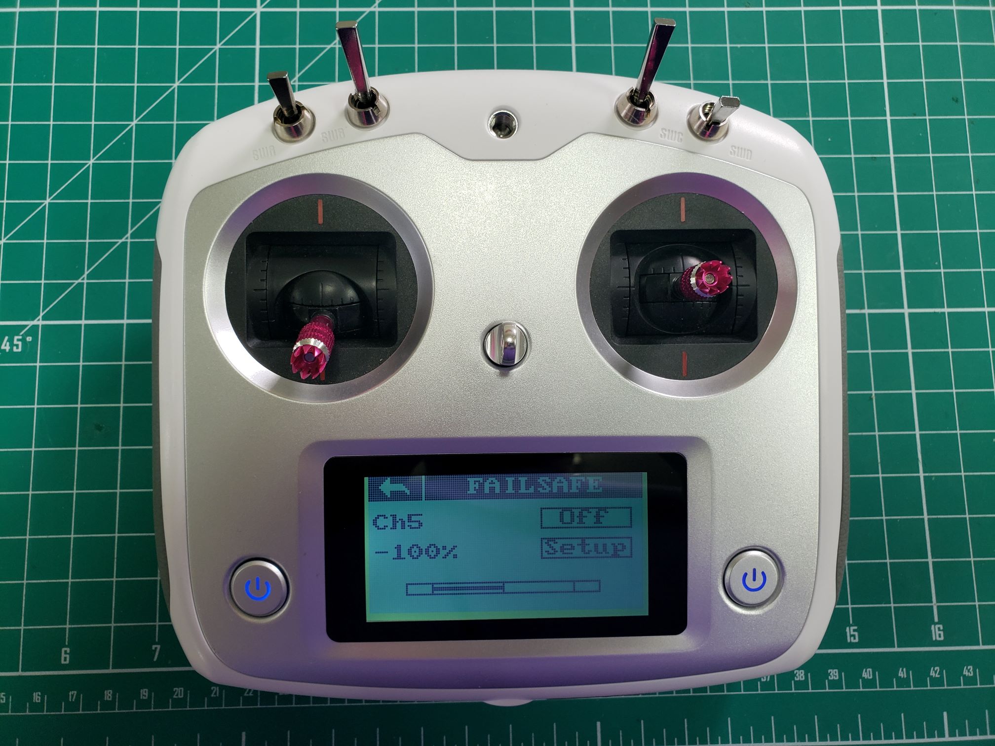
CH5/SWA default switch position up with a value of -100%
Tap the back arrow and complete the process for Channels 6-8. Keep in mind that since
CH8 (switch SWD) is in a downward position the value will be +100% as shown in
the photo below.
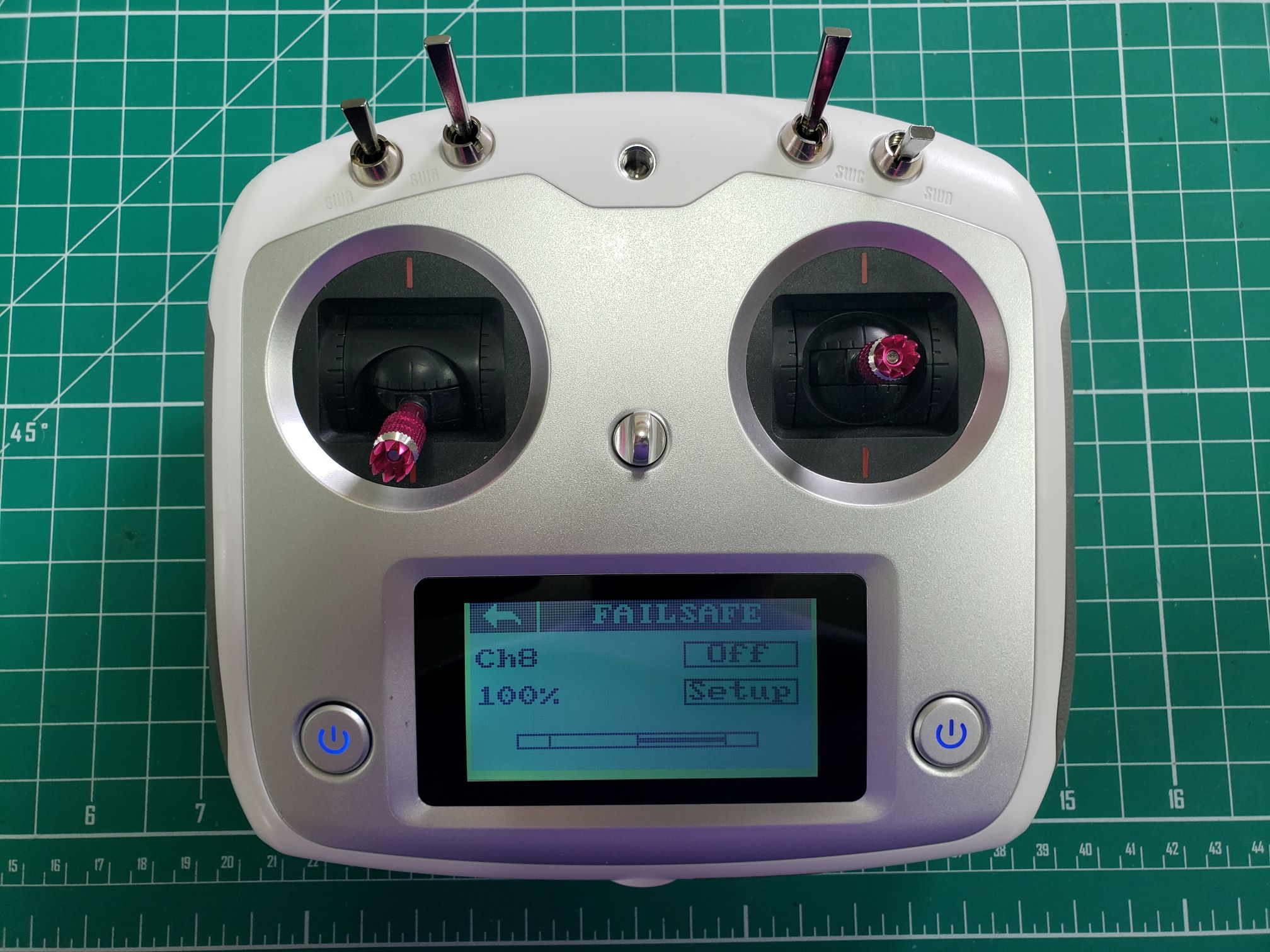
CH8/SWD down switch position with a value of +100%
The following photo shows the final failsafe values for Channels 5-8. These are the
values that will be sent from the receiver to the FC in case there is a loss of signal
with the transmitter.
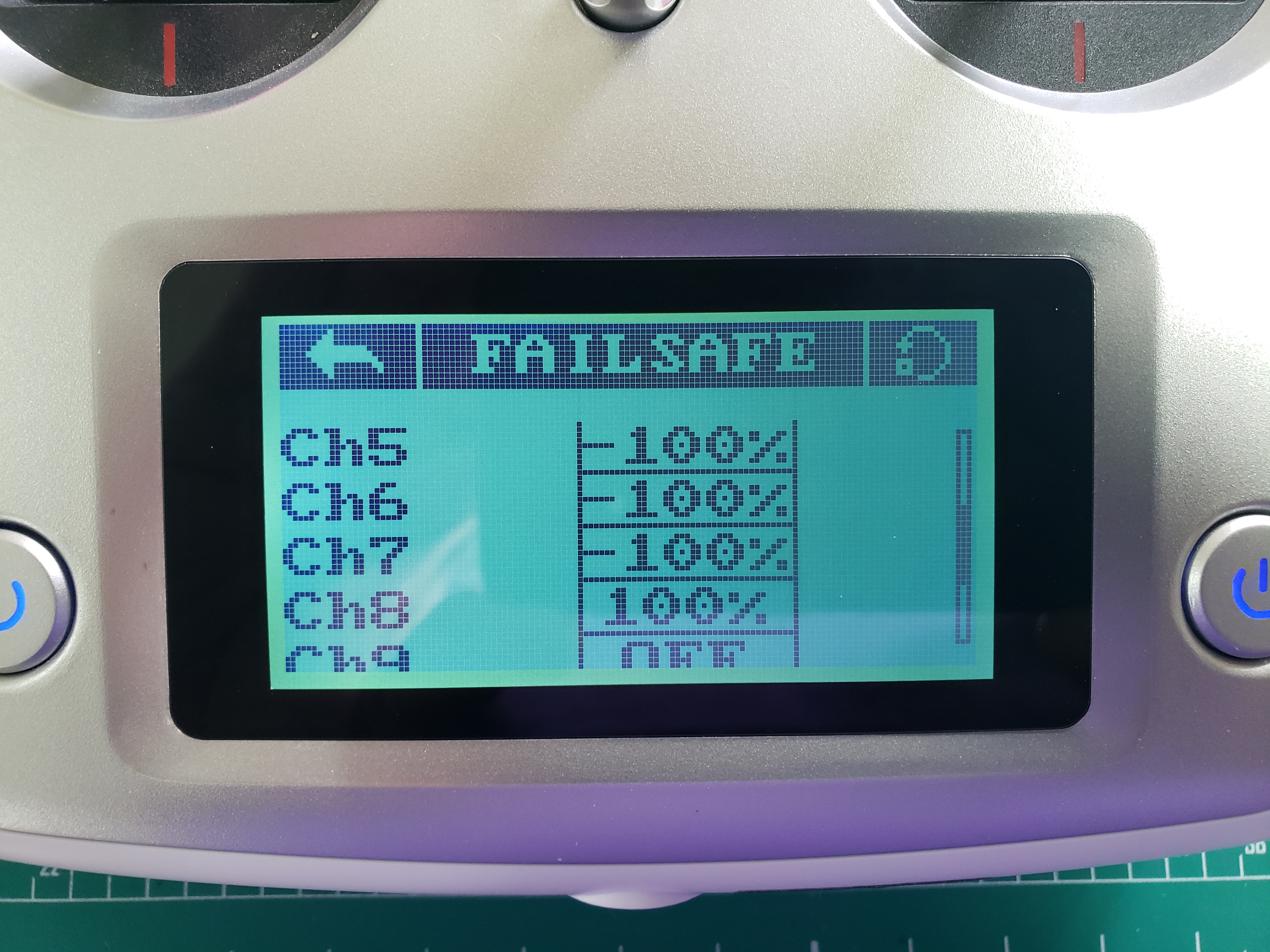
Failsafe configuration for channels 5-8
The failsafe values for all channels have been configured. In the end, you should have
the following failsafe values for each of the channels:
| Channel | Fail-safe value | Stick/Switch Position |
|---|
| 1 (Roll) | 0% | Right stick centered |
| 2 (Pitch) | 0% | Right stick centered |
| 3 (Throttle) | -100% | Left stick down and centered |
| 4 (Yaw) | 0% | Left stick down and centered |
| 5 | -100% | SWA up |
| 6 | -100% | SWB up |
| 7 | -100% | SWC up |
| 8 | 100% | SWD down |
Your transmitter setup is now complete and we will move on to setting up and calibrating
the FC.
Warning
Setting up proper fail-safes is very
important for your own safety and the safety of your environment! Please take the time
to carefully review this page one more time.