Flight Controller Setup and Calibration w/ QGC
In this section we’ll walk through the final steps of loading firmware and calibrating your drone before your first flight.
QGroundControl (QGC)
Ground control software is used for configuration and monitoring of your AVR drone. We
will be using QGroundControl as our ground control software of choice throughout AVR.
With QGC you can upload firmware, configure flight modes, calibrate sensors and much
more. It also provides different ways of controlling the drone, such as an autonomous
mission planner.
QGC can be downloaded and installed on Windows, Mac, and Linux operating systems. You
can find the necessary installer by going to the
downloads page.
Using the daily build, follow the steps
here
for your operating system.
Go ahead and install QGC before proceeding to the next section.
Note
For Ubuntu 22.04 users, you may need to
additionally install libfuse2 before the AppImage will work:
sudo apt install libfuse2
The following sections will guide you through the process of using QGC to set up your
FC. Let’s get started!
1 - PX4 Firmware
Uploading PX4 firmware using QGC
PX4 is firmware that we will be running on the AVR drone. It is an
open-source flight stack containing all the software necessary to get your drone into
the air.
To facilitate some of the extra functionality required for our drone to fly in
stabilized flight mode without a GPS, you will need a custom version of PX4 Bell
engineers have developed. Go to the latest
AVR PX4 release and
download the px4_fmu-v6c_default.<px4 version>.<hash>.px4 file.
Note
Be sure you grab the correct 6c firmware,
there will also be a 6x build, px4_fmu-v6x_default, but that is for a different flight
controller and is NOT to be used.
In the Firmware screen in QGroundControl you can upload a new version of PX4. To access
the firmware screen make sure to click on the Q logo in the top left of the screen and
then click on Vehicle Setup > Firmware. You will see the following screen.
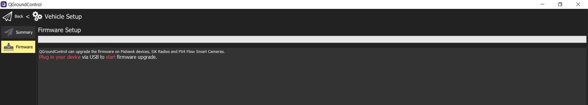
Firmware upload screen in QGC
Note
Make your FC is NOT plugged in when
accessing the firmware setup screen. First access the firmware screen and THEN plug
in your FC. It will recognize the connection and initiate the process.
QGC will ask you to plug in your FC using a USB cable. A popup will appear that asks you
which firmware you want to use. select “Advanced Settings”, then “Custom firmware
file…”
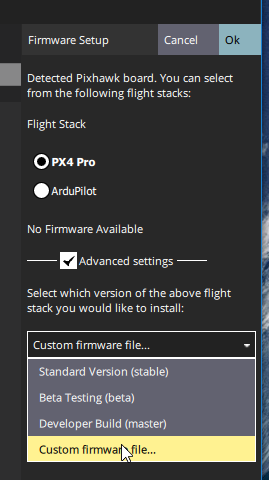
Loading PX4 Pro Stable Release onto FC
Then click “Ok” and select the firmware file you downloaded. Now, you will see a
progress bar. This process should take no more than 2-3 minutes.
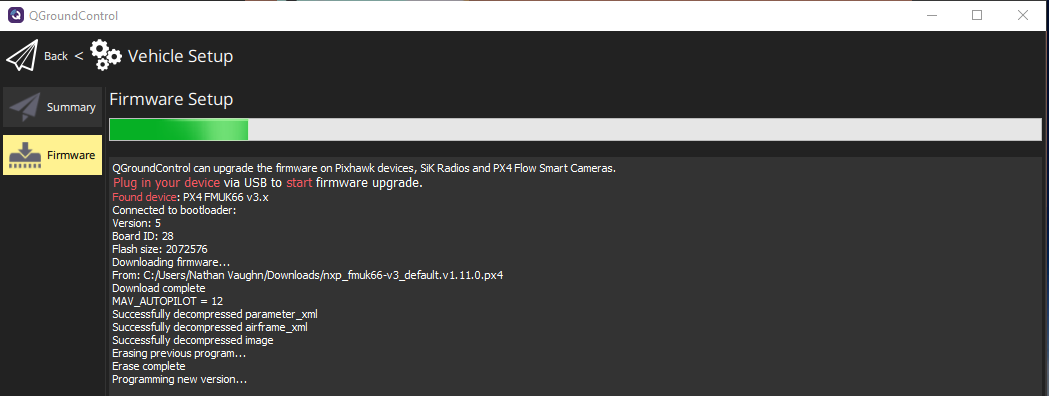
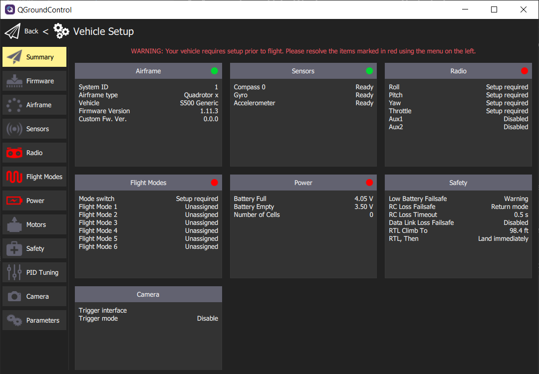
After the PX4 firmware is successfully loaded you will be presented with the default
Vehicle Setup screen. It is necessary to go through the following steps to ensure a
reliable and stable first flight.
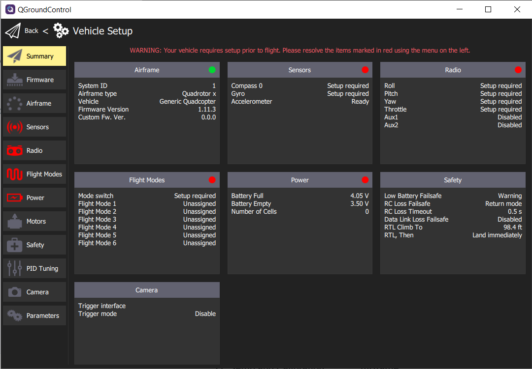
QGC Vehicle Setup screen right after PX4 firmware load
2 - Airframe
The AVR drone is 500mm in size and is represented by the diagonal distance between
motors. If you were to measure the distance it would be close to 500mm. In QGC you will
now configure the drone frame, which will provide optimal settings for flight. Select
Airframe in the navigation menu.
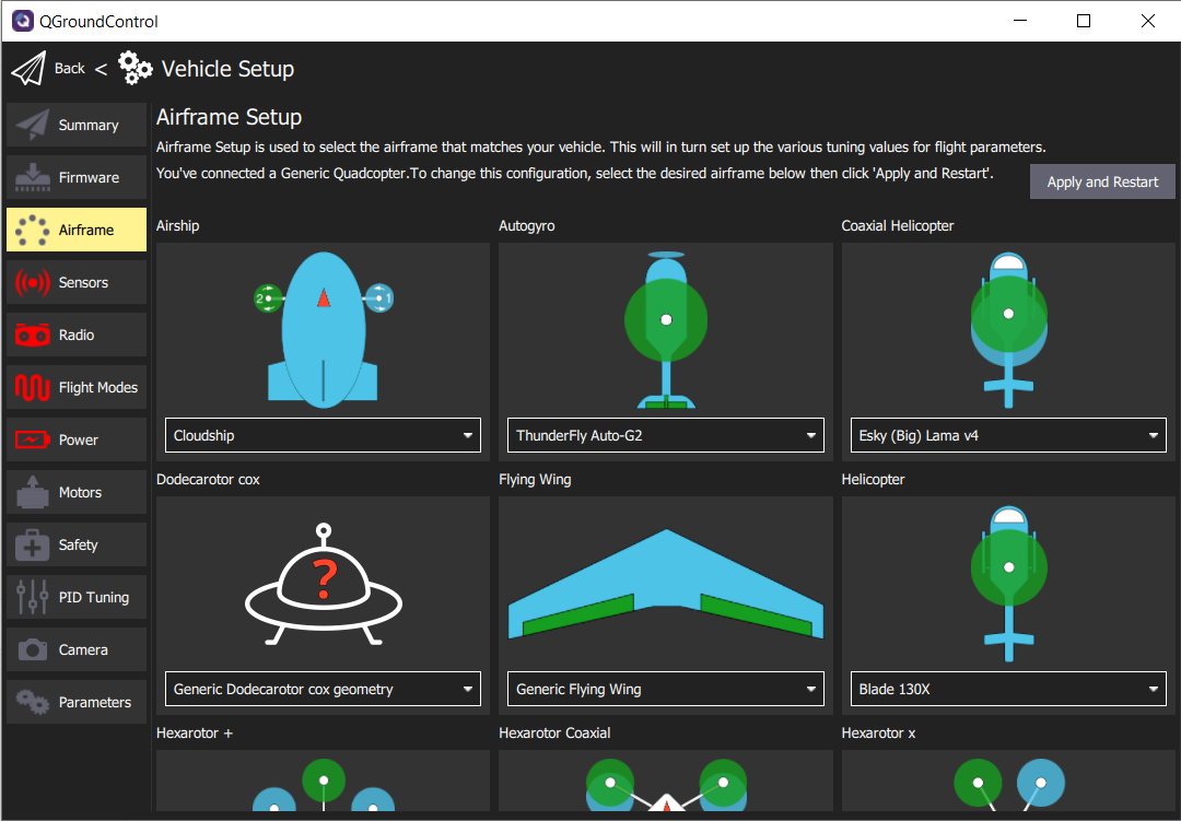
Airframe Setup screen
Scroll down in the Airframe Setup screen and look for Quadrotor x. Click on the
dropdown menu and select S500 Generic as the airframe type. Scroll back up and click
the Apply and Restart button in the top right of QGC. You will be asked to confirm
that you want to restart. Click Apply and the airframe setting will be saved.
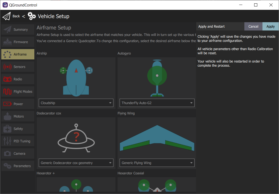
While the FC is rebooting QGC will disconnect for a few moments and then automatically
reconnect.
3 - Sensors
The Sensors screen lists most of the sensors that are available to the FC (internal
or external). It allows you to start the calibration process for the listed sensors.
This step is very important for stable flights. It is required to do the calibration at
least once and should be repeated whenever adding new components to the AVR drone or if
flight becomes less stable.
Note
Given advanced assembly of your drone will
require additional autonomy components and peripherals, it is a good practice to
understand the calibration process in detail.
Click on Sensors in the navigation menu and let’s walk through the calibration
process for each sensor.
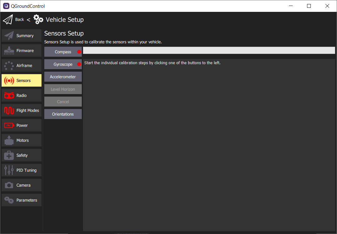
Default Sensors screen
Compass
The compass is important for your AVR drone to maintain proper orientation. Click on the
Compass button and you will be asked to begin the calibration process. This process
requires you to position the AVR drone in a number of set orientations and rotate the
vehicle about the specified axis.
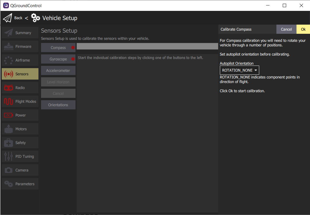
Default compass sensor screen before calibration begins.
Click Ok to proceed with the compass calibration. QGC will automatically recognize
the orientation of the AVR drone and provide a yellow highlight as shown in the image
below.
Note
Don’t be thrown off by the images of an airplane
in the QGC compass calibration process. This still applies to the AVR drone.
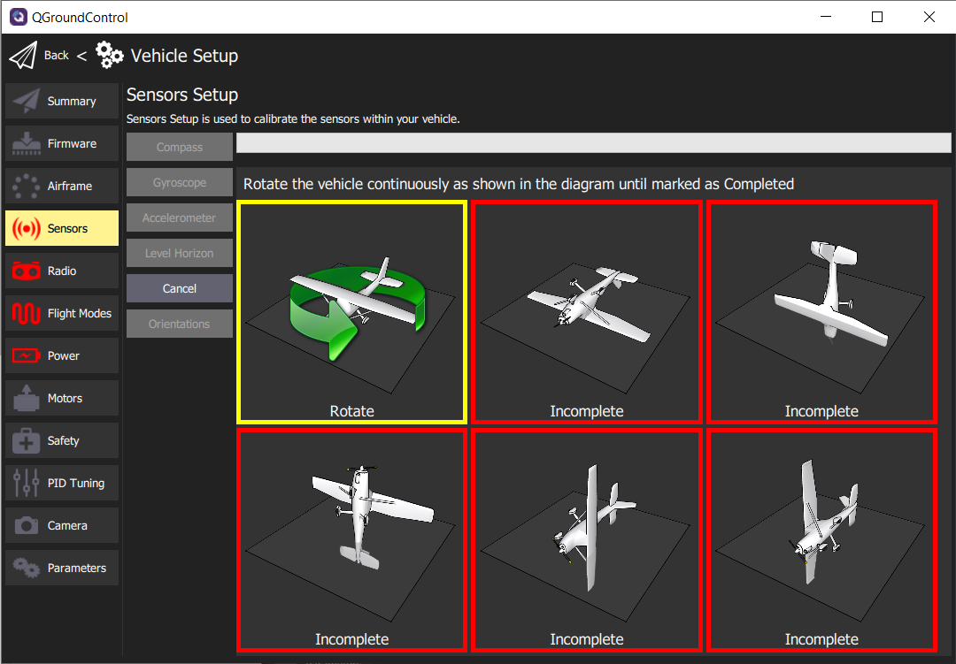
Begin the process of rotating the AVR drone around the highlighted axis.
Tip
You may find it difficult to rotate the AVR drone
with USB connected. It is helpful to have someone keep the cable out of the way while
another rotates the drone around its designated axis.
Once the orientation is highlighted you can begin rotating the drone until the box is
highlighted green. This generally requires one 360 degree rotation around the axis. The
image below shows three of the six orientations completed.
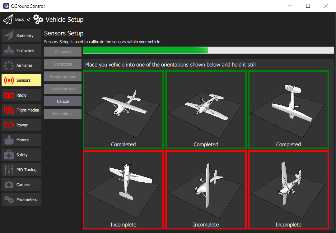
Compass calibration in progress
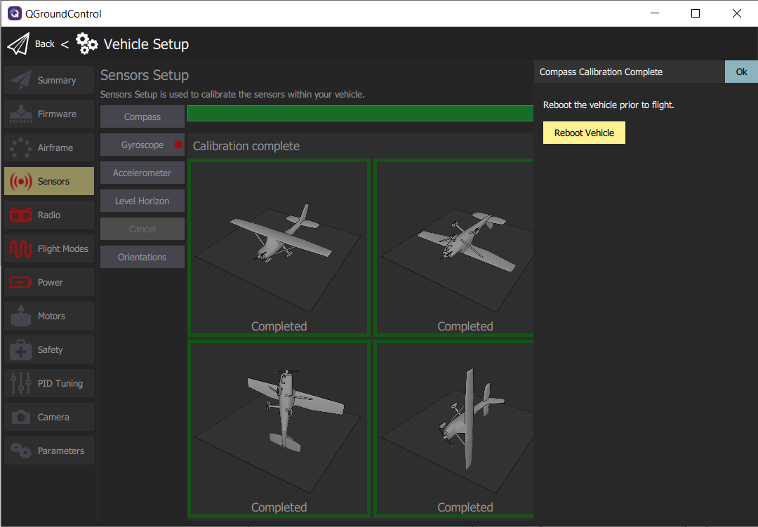
After completing the calibration of all axes click Ok to return to the sensor setup.
It is important to reboot your FC prior to flight, but for now we will move on to
calibrating the Gyroscope.
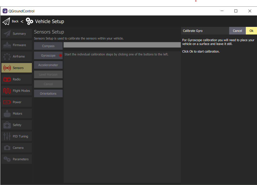
Gyroscope
The gyroscope is an important sensor that will be used to keep your AVR drone level when
hovering. Now that the compass calibration is complete you will click on Gyroscope to
being the process. This will be much easier than compass calibration! Make sure your AVR
drone is on a level surface and click Ok.
After a few seconds, the gyroscope calibration will be complete.
Successful gyroscope calibration
Accelerometer
The accelerometer works in conjunction with the gyroscope to keep your AVR drone level
along each axis. Click on Accelerometer and then Ok to begin the calibration
process.
This process is fairly similar to compass calibration but does not require you to rotate
the drone around each axis. You simply need to hold the drone level in each orientation.
QGC will detect the orientation, which is denoted by the yellow border.
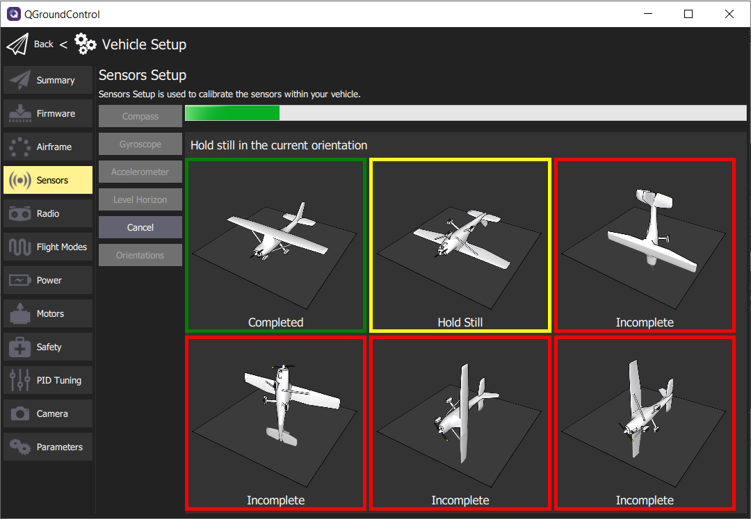
Accelerometer calibration in progress
Hold your AVR drone steady in each orientation for approximately 5-10 seconds. As you
complete each axis the border will turn green in QGC.
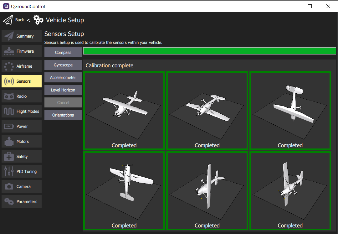
Accelerometer calibration complete
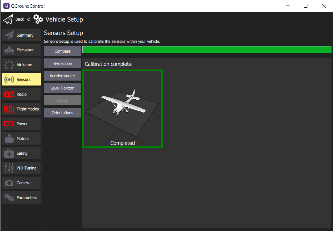
Level Horizon
Level horizon is a simple calibration to make sure your FC understands the default level
position when powered on. Click on the Level Horizon button and then Ok. This
process will take more than a couple of seconds to complete.
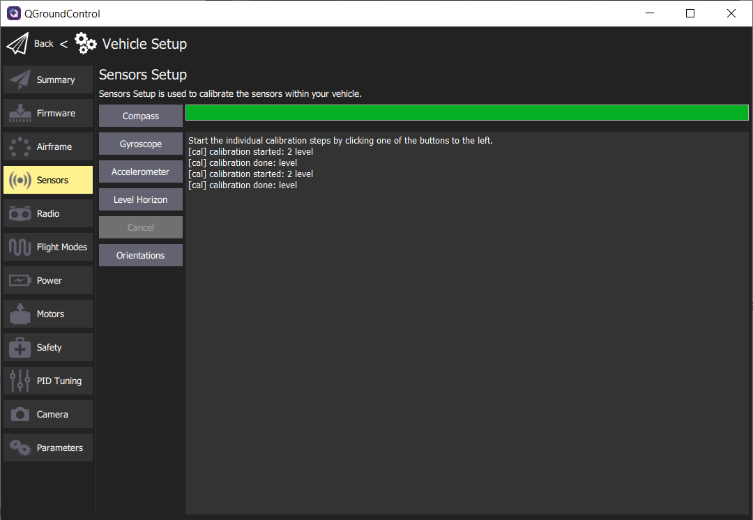
Level Horizon calibration complete
Orientations
Given we have mounted the FC in its default orientation (facing up and forward) this
calibration is unnecessary.
Nice work! You have calibrated the necessary sensors for your AVR drone to be able to
know its orientation and keep level during flight. The following Summary screen shows
the successful steps completed in green. Now we will move onto setting up the Radio
(aka Transmitter).
Summary screen showing all sensors calibrated and ready for flight
4 - Radio
In the RC Transmitter Setup section we
configured the stick and switch channels. Now we will calibrate the endpoints of these
channels so they can be saved to the FC. QGC makes this very easy to do and the process
can be observed in the following video.
Now that your transmitter has been calibrated using the Radio screen in QGC we will move
onto setting up our flight modes.
5 - Flight Modes, Arming, and Kill Switch
The primary goal of the basic assembly is to be able to pilot the AVR drone in
stabilized mode. Therefore we will configure SWB (3 position switch) to control which
flight mode we’re in. In addition to setting up flight modes, we will also enable a kill
switch on SWD (2 position switch). This is VERY IMPORTANT in case the AVR drone
needs to be shut down due to a fly-away or complete loss of control. The video below
demonstrates this process.
6 - Power
Power Setup
For correct display of battery percentage, you should always specify the correct number
of cells in the battery. In our case this will be 4 since we are using a 4 cell LiPo
battery. You should also calculate the value for the voltage divider to calibrate the
voltage readings coming from the power module. This can be done by measuring the overall
voltage with the Venom cell checker. Then you can input the measured voltage into the
Calculate Voltage Divider prompt.
These settings will provide you with an accurate battery percentage while the drone is
idle on the ground, so you can determine whether it is still safe to take off and when
you need to land. PX4 also has a fail-safe that prevents arming when the battery
percentage is too low. The video below walks through the power setup.
ESC Calibration
To ensure that all motors correctly respond to commands coming from the FC, you should
perform an ESC “calibration”. It makes sure that the ESCs are aware of the minimum and
maximum pulse-width modulation (PWM) values that the FC provides. This can be done by
pressing the ESC calibration button and following the on-screen prompts. The calibration
process requires a USB connection since it involves steps where you have to disconnect
and reconnect the battery. The video below covers this in detail.
7 - Safety
Safety Setup
Previously, in the RC Transmitter Setup section, we covered Setting Up
Failsafe. In QGC we
need to make sure we disable some of the failsafe options, as many of them are related
to GPS-enabled drones. AVR is all about indoor navigation in a GPS-denied environment
therefore it warrants a different safety configuration. The video below walks through
the setup process.
8 - Motor Test
One physical check that must be done to ensure your AVR drone hovers properly is to
verify that the motor positions and rotations are correct. We previously covered ESC
wiring which should ensure that the FC output is going to the right motor.
We discussed motor rotation when installing the frame arms and learned that the rotation
for each motor is important. You may recall the image below and we will refer to it one
more time before we run the motor test.
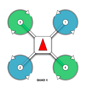
Motor position and rotation diagram
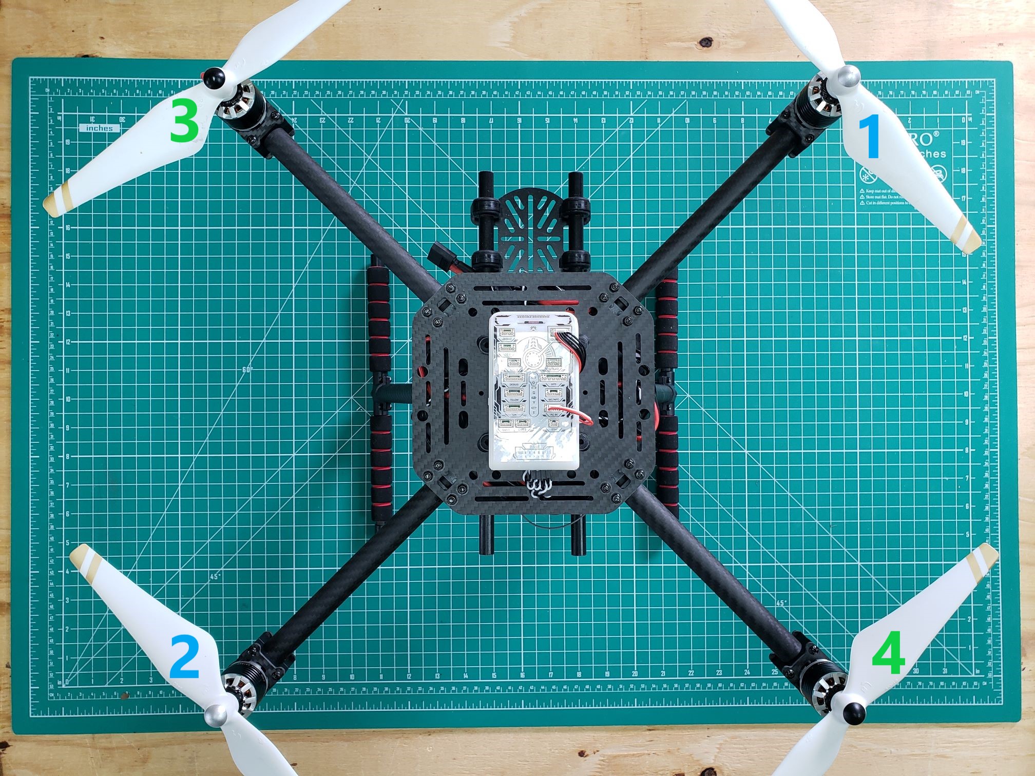
Motor positions and propellers installed with the nose of the AVR drone pointed forward
The video below will walk through the necessary steps to run the position and rotation
test.
Tip
It is not necessary to do this motor test every
time you fly, but it is highly recommended if any wiring modifications have been made to
your AVR drone.