Overview
This section details how to assemble your gimbal. The gimbal allows the ground station operator to aim the FPV camera, thermal camera, and laser pointer at targets on the field independently of the drones position/orientation. The gimbal assembly will be used to detect hot spots on the field, put out fires using your water cannon, and perform reconnaissance with your FPV camera .
The gimbal uses 2 servos (very similar to servos used in previous years) to control the pan and tilt of the drone.
Pan is the rotation about the z-axis meaning this controls the left or right camera angle. Pan gets its name because it keeps an object in the picture or secures a panoramic effect.
Tilt is the rotation abut the y-axis meaning it controls the up and down camera angle.
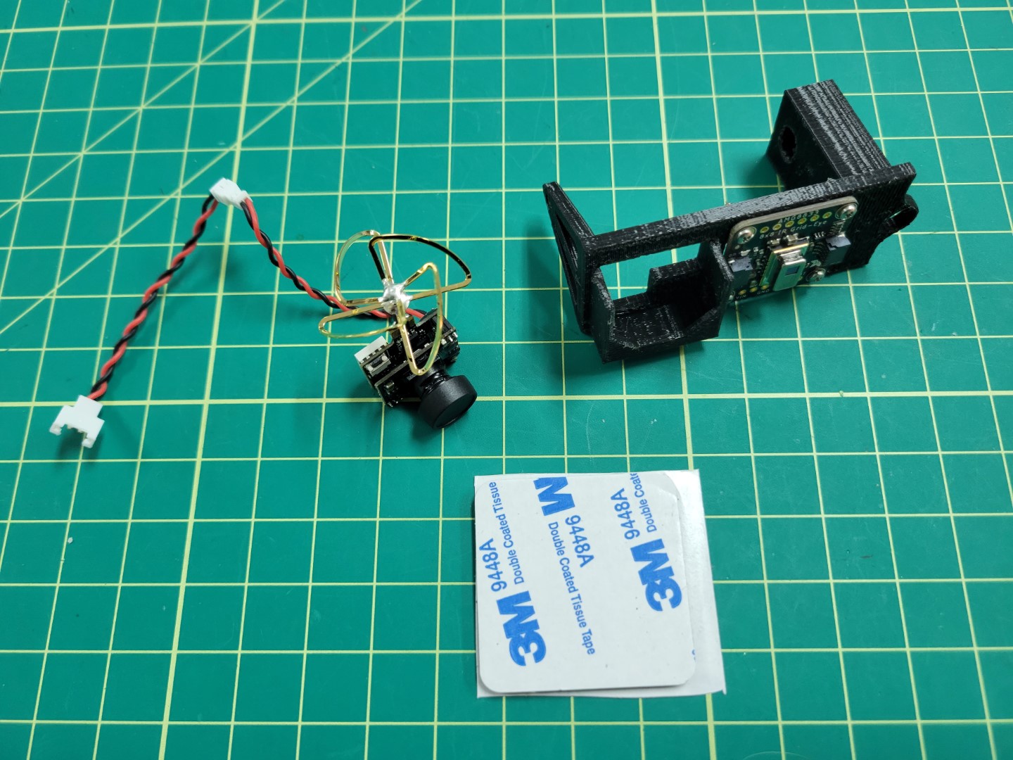
Obtain the gimbal parts from the 3D printing section, 2 servos and associated hardware, a MOSFET, the thermal camera, laser module, FPV camera, and long F-F dupont jumper wires.
Note
Be sure you have the latest 3D printed parts as there have been changes to the pan part to accommodate your specific servo horn.
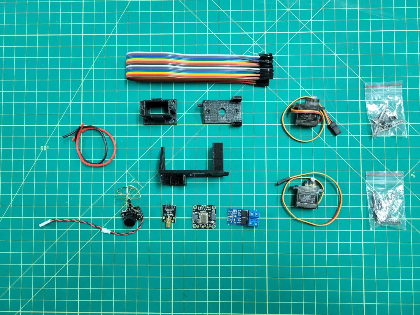
Gimbal Parts Overview
Gimbal Base
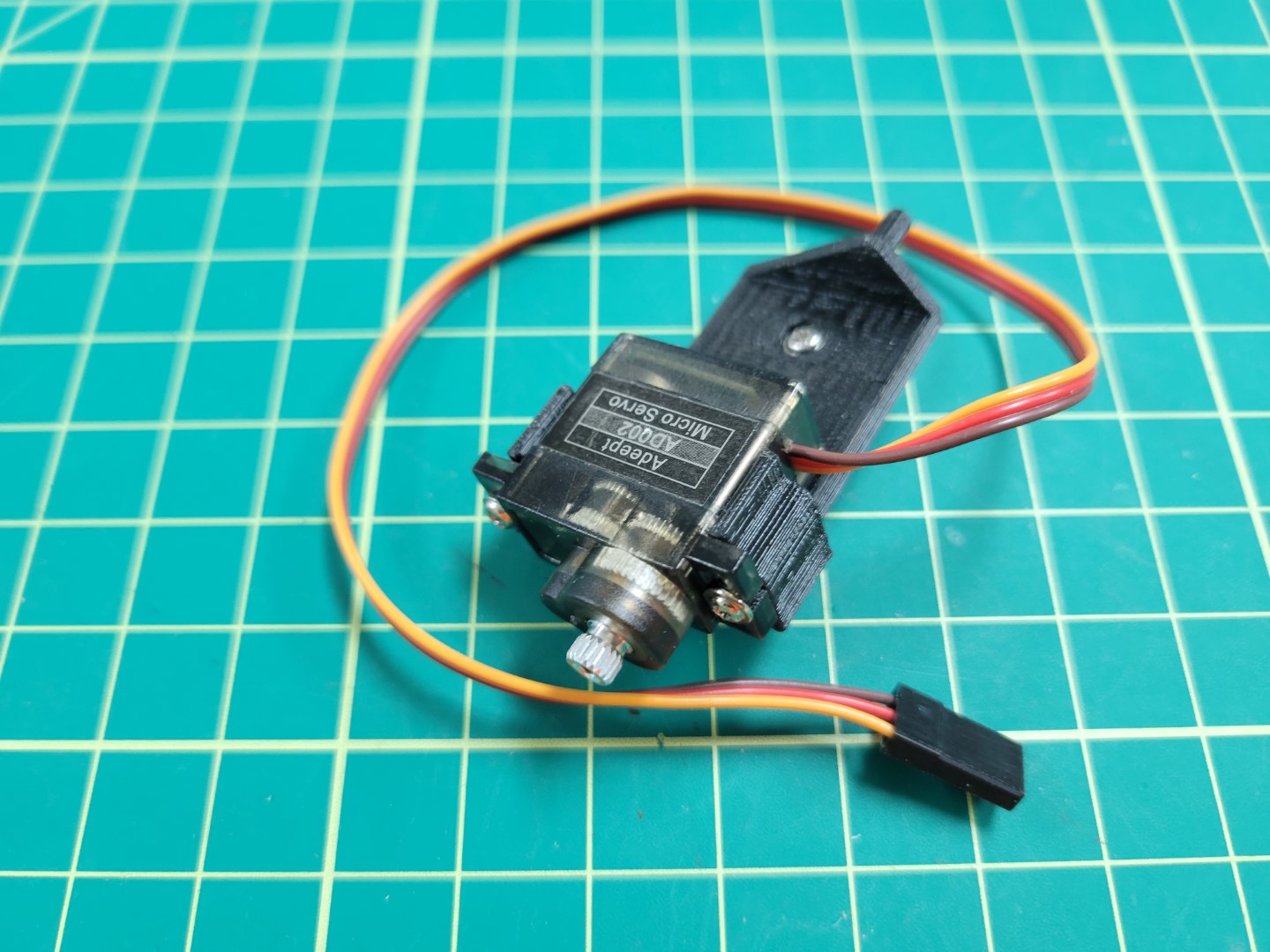
Start with the gimbal base. Pass your servo wire through the slot on the slide and slide servo into place.
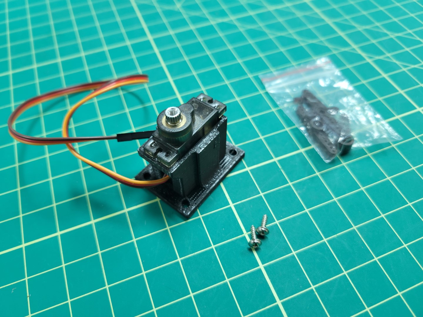
Gimbal Base Servo Placement
Secure the servo into the gimbal base using the servo hardware screws as shown below.
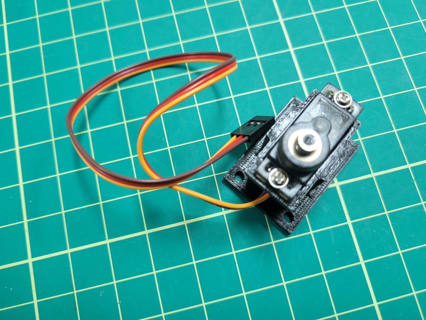
Gimbal Base Servo Mounting
Gimbal Pan
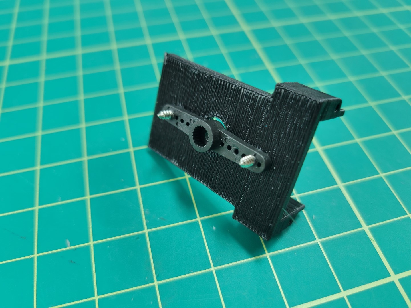
Next you will attach the servo horn with 2 arms to the bottom of the gimbal pan part using the servo hardware.
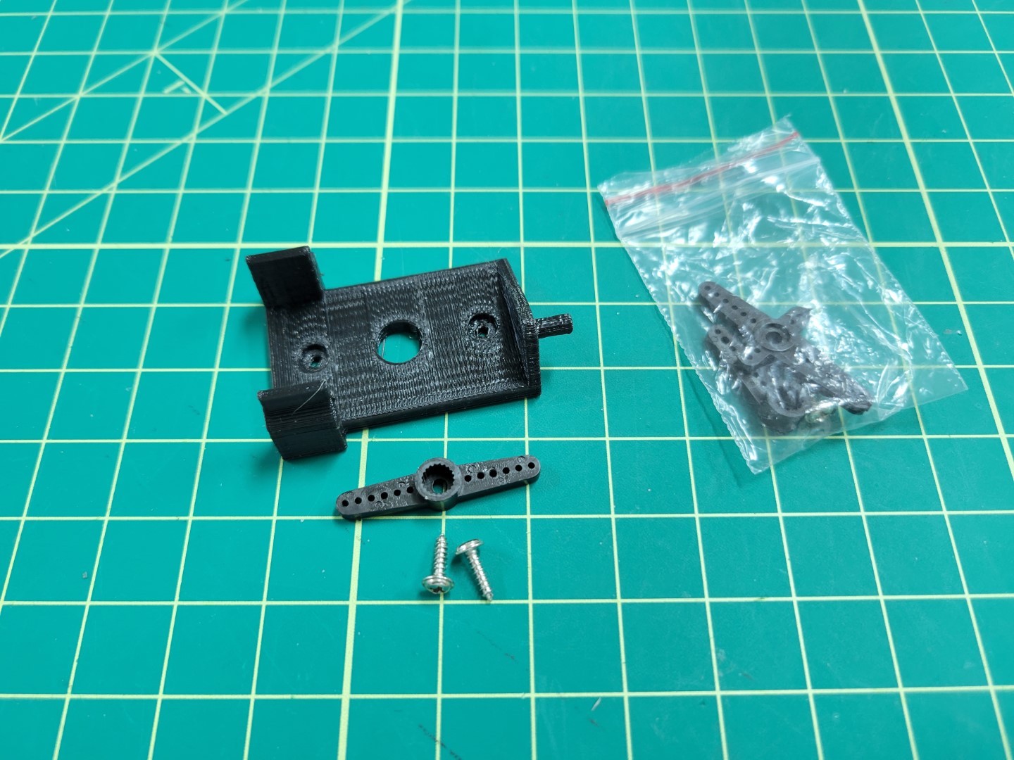
Gimbal Pan Servo Hardware
Be sure the geared part of the servo horn is facing away from the connecting face. Align the center hole and the 2 holes (one hole away from the end of the servo arm) with the holes on the pan part. Screw through the part to attach your servo horn to the pan part.
If done successfully your screws heads should sit flush with the bottom of the gimbal pan.
Gimbal Pan Servo Horn Attachment
Place a second servo in the gimbal pan part, this servo will be used to control the tilt of the gimbal. The gimbal gear and the tilt attachment arm should be on the same axis. Align the servo gear with the tilt attachment arm of the opposite side of the 3D printed part. Screw the tilt servo into the two holes on the side pan assembly; the final product of which should look like the following photo.
Tilt servo attached to gimbal pan part
Gimbal Tilt
Next we will be assembling the tilt mechanism. This is where all of our sensors will be mounted.
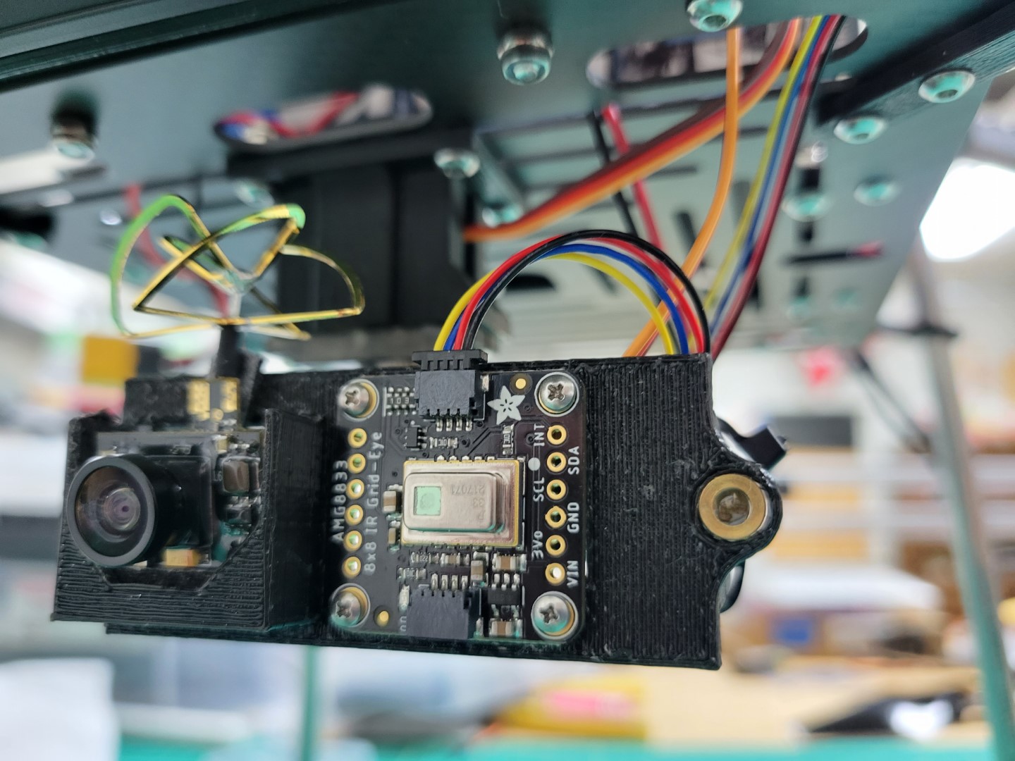
Thermal Camera Mounting
The thermal camera will be mounted in the center of our gimbal tilt part. Use 4 screws from the peripheral bag to attach the thermal camera to the drone.
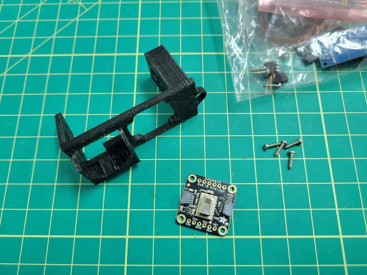
Thermal Camera Mounting Overview
After screwing in, it should look like the photo below.
Note
Make note of the thermal camera’s orientation. This will be important for properly viewing the thermal image in the AVR GUI.
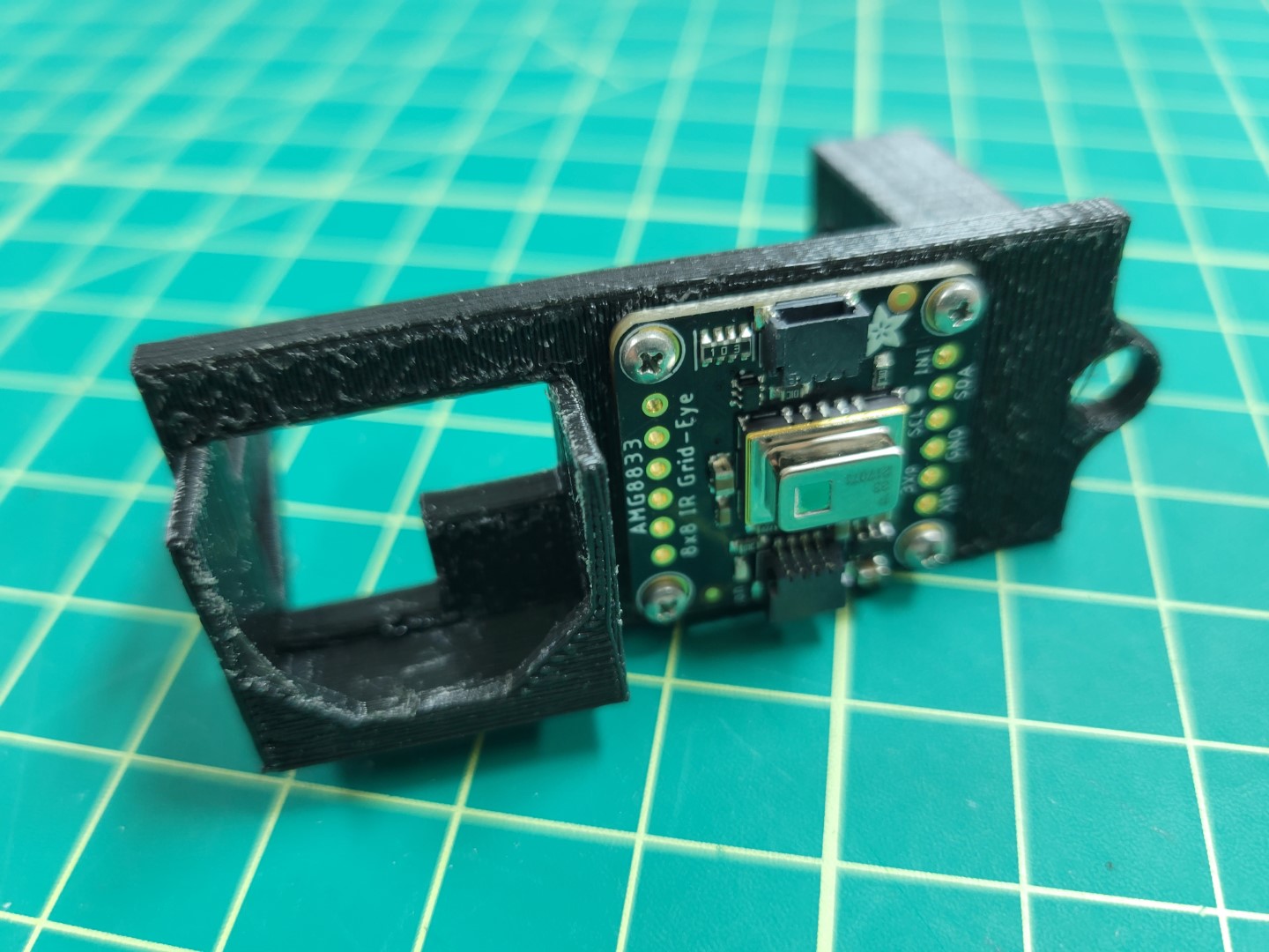
Mounted Thermal Camera
We will wire and test this in following sections.
FPV mounting
The FPV camera is mounted on the left side of the part (as shown in the picture).
FPV Mounting Overview
Cut a 3M double sided tape to the size of the base of the protruding area of the tilt part and place.
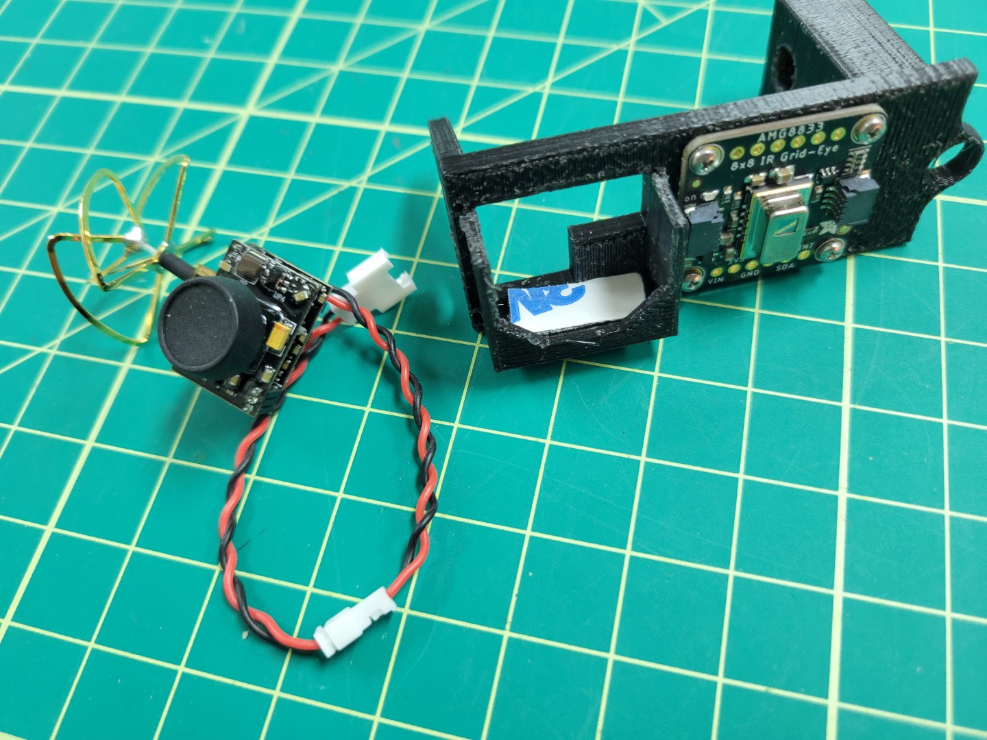
FPV Double Sided Tape Placement
Slide the camera into the slot and ensure that the camera is secured. You should be able turn the part upside down without the camera falling out.
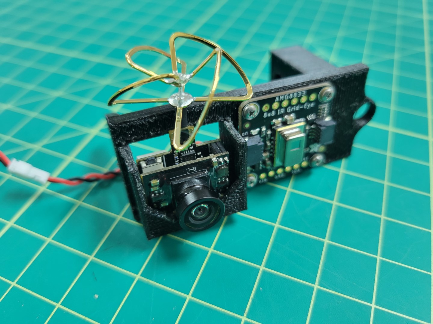
FPV Mounted in Tilt Assembly
We will wire and test this in following sections.
Mount Servo Horn
Next place your servo horn into the the recess on the tilt part. We find that using a small amount of super glue is helpful in holding the servo in place before we attach it.
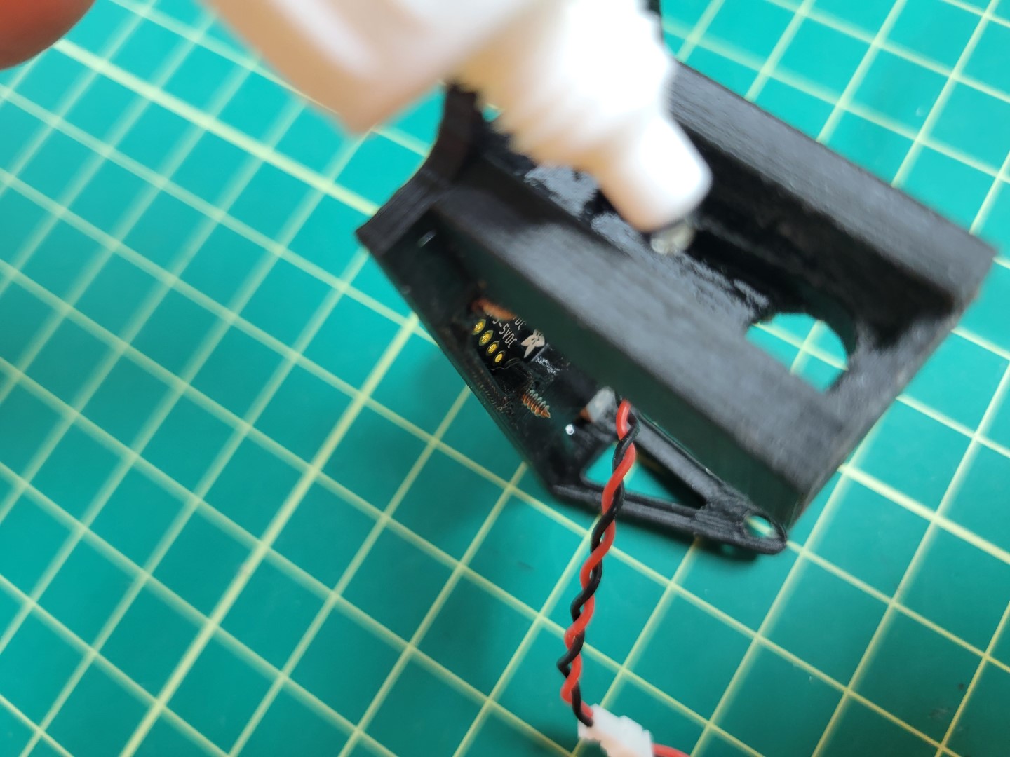
Tilt Servo Horn Mounting
The only remaining part of the gimbal assembly components is the laser, but we will come back to that after fully assembling the gimbal on the drone.
Gimbal Assembly
Now that all of the assembly 3D parts have been assembled we can start mounting the gimbal to the drone.
Note
Before performing this section, ensure you have connected to your drone with the GUI as we will need to use it in order to calibrate the Gimbal.
First, mount the Gimbal base to the drone using 10mm 3M screws included in your kit. Use the 1st and 3rd slotted holes from the front of the drone to mount the gimbal base.
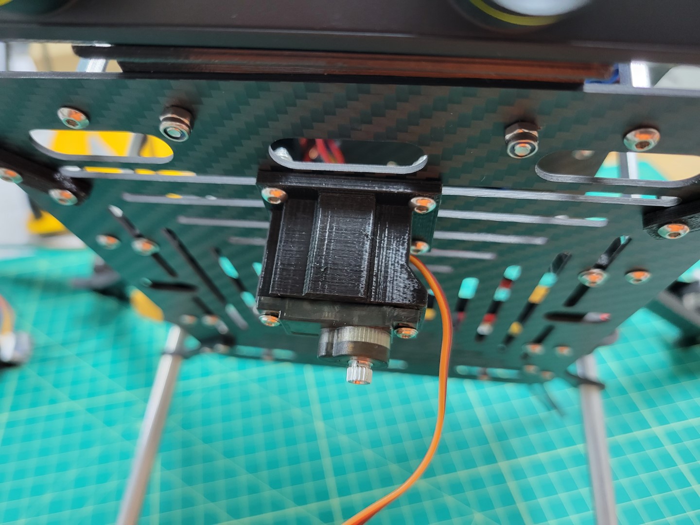
Gimbal Base Mounted
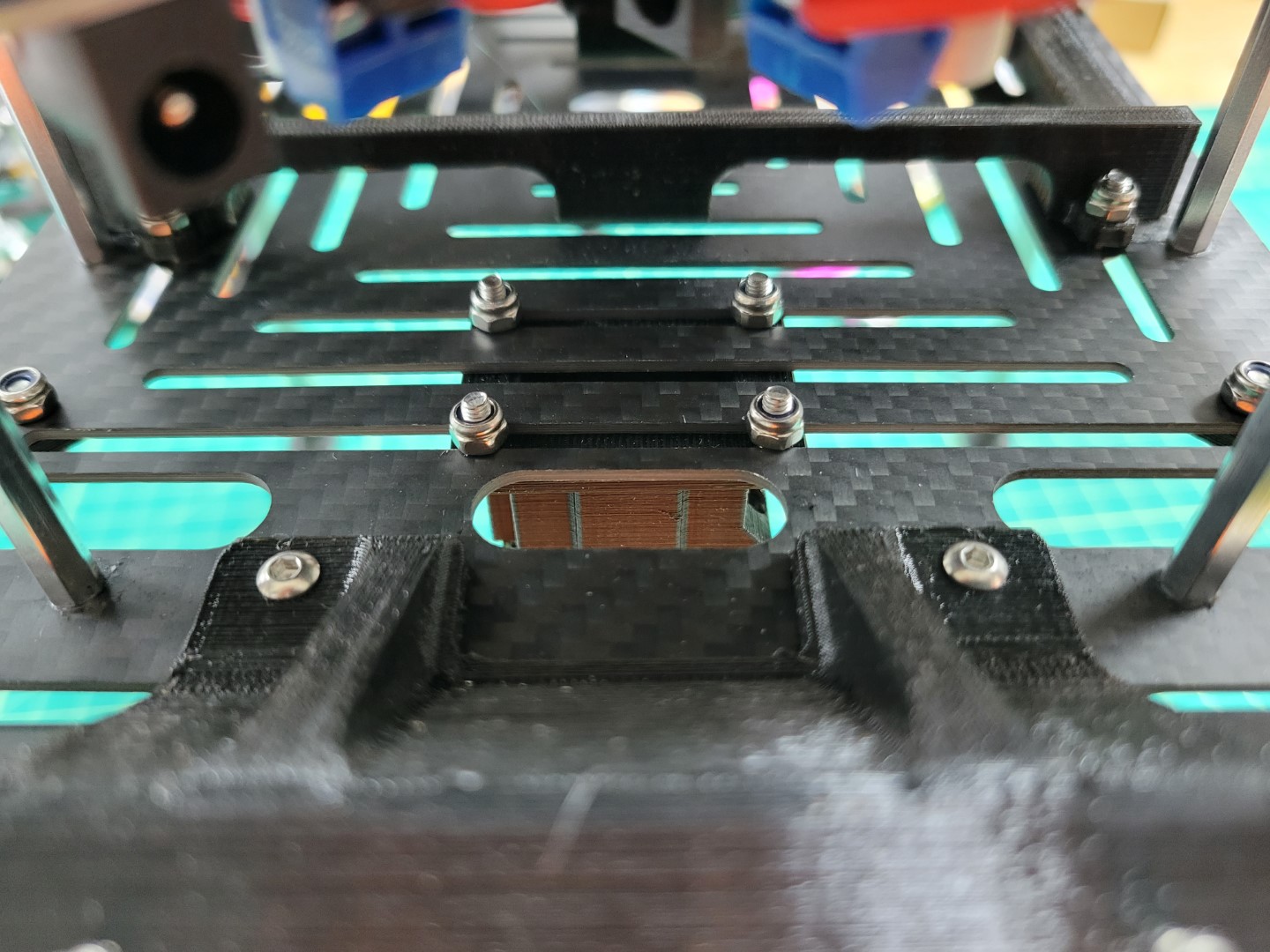
Lock Screws
Pan and Tilt Calibration
Please watch the video below to understand calibrating your gimbal’s pan and tilt range of motion.
Note
If you do not have the “invert joystick” option in your GUI be sure you have the latest release of the GUI.
Command used in the video:
./start.py run mqtt pcm
Pan and Tilt Servo Wiring
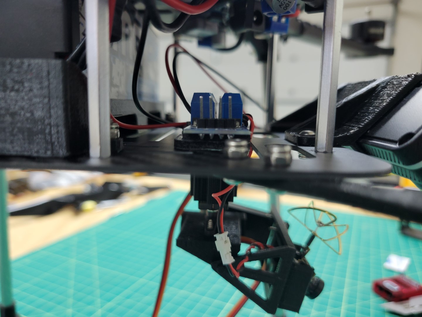
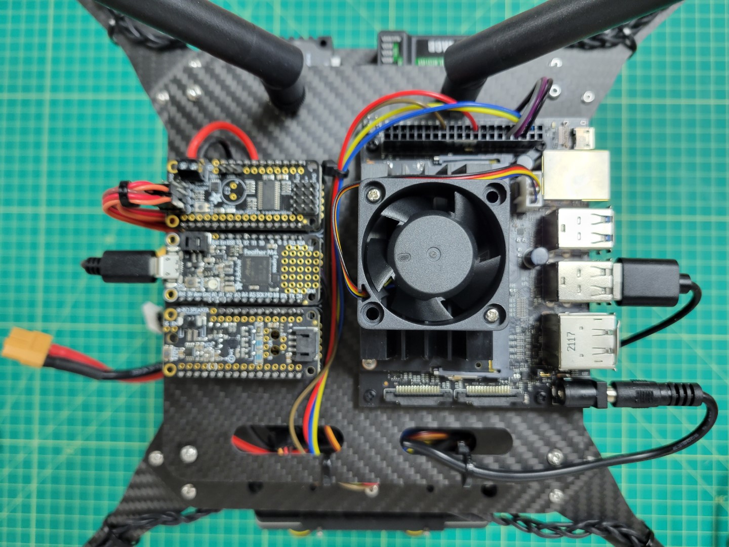
You can clean up your servo wiring by using 12" servo extenders. You will run them up through the bottom, mid, and top plates and finally connect them to your PCC as shown in the photo below.
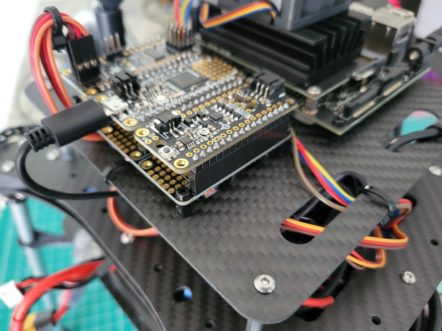
12" servo extenders routed up to PCC
There is no right or wrong way to manage your servo wiring. The only important thing is that you have your pan and tilt servos plugged into the correct ports as covered in the calibration video.
Laser Pointer Mounting
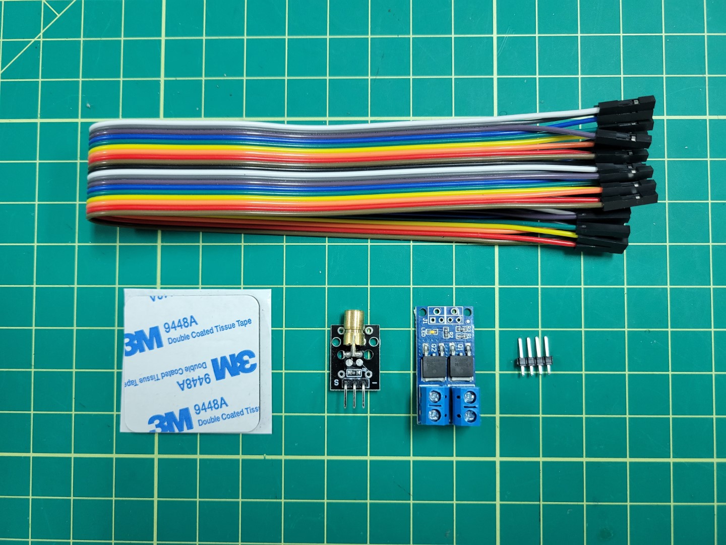
Components for laser mounting and wiring
Cut a small piece of your 3M double sided tape and place it on the end of your laser pointer being sure not to obstruct the view of the laser barrel.
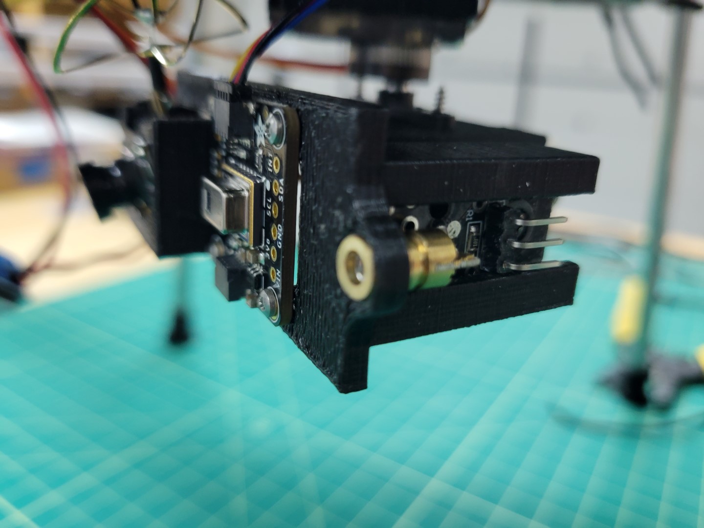
Laser mounted in gimbal
Powering Laser and the FPV
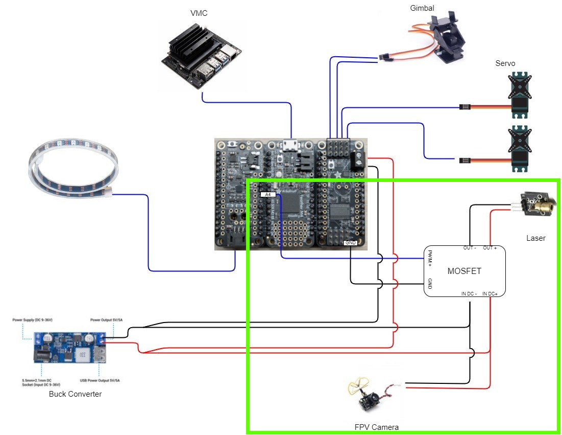
Next we will be focusing on the FPV and the Laser wiring as shown in the following wiring diagram.
PCC Wiring
Solder extra header pins from the PCC section onto MOSFET pins J1.
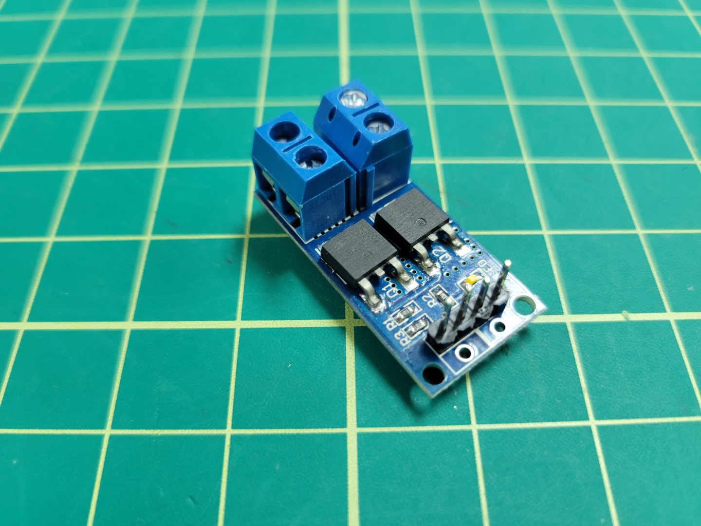
MOSFET with header pins soldered
Cut wires (black and red) approximately 6" in length.
Screw wires into the PCC Buck converter output terminal. There will be two wires coming out of the positive and negative terminals as shown in the photo below.
Leads that will power MOSFET
Cut the extender provided with the FPV camera at the connector as shown in the following photo.
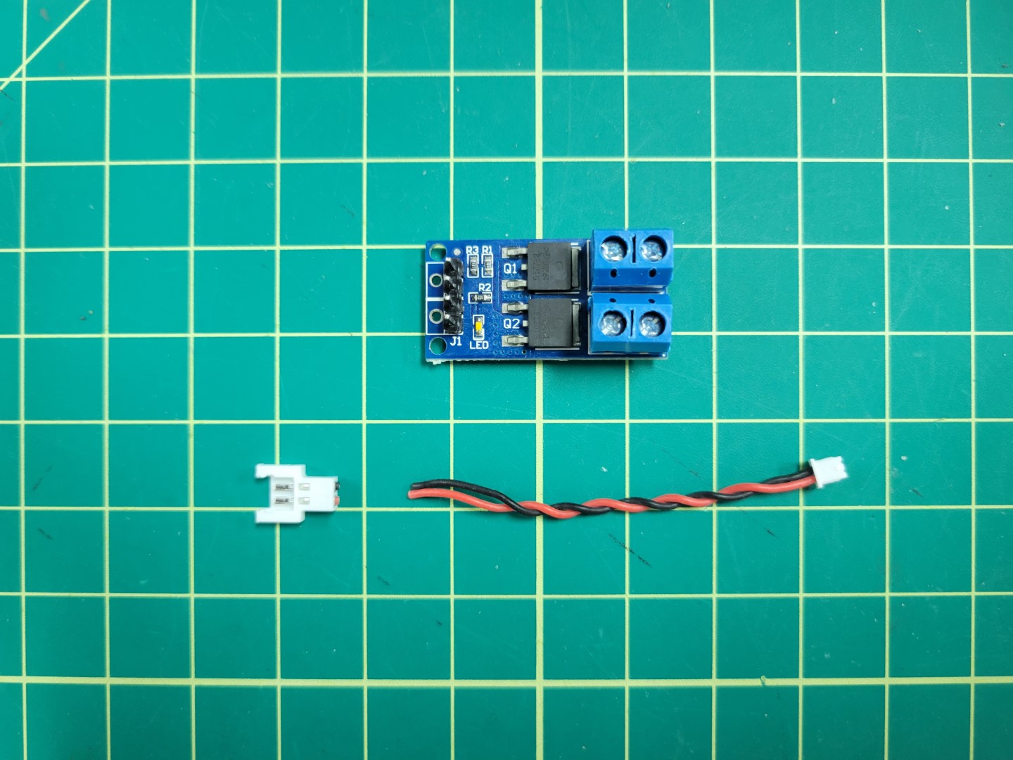
FPV camera cable ready to connect to MOSFET
Place both the power and FPV wire ends into the MOSFET input terminals and screw down to terminal to secure.
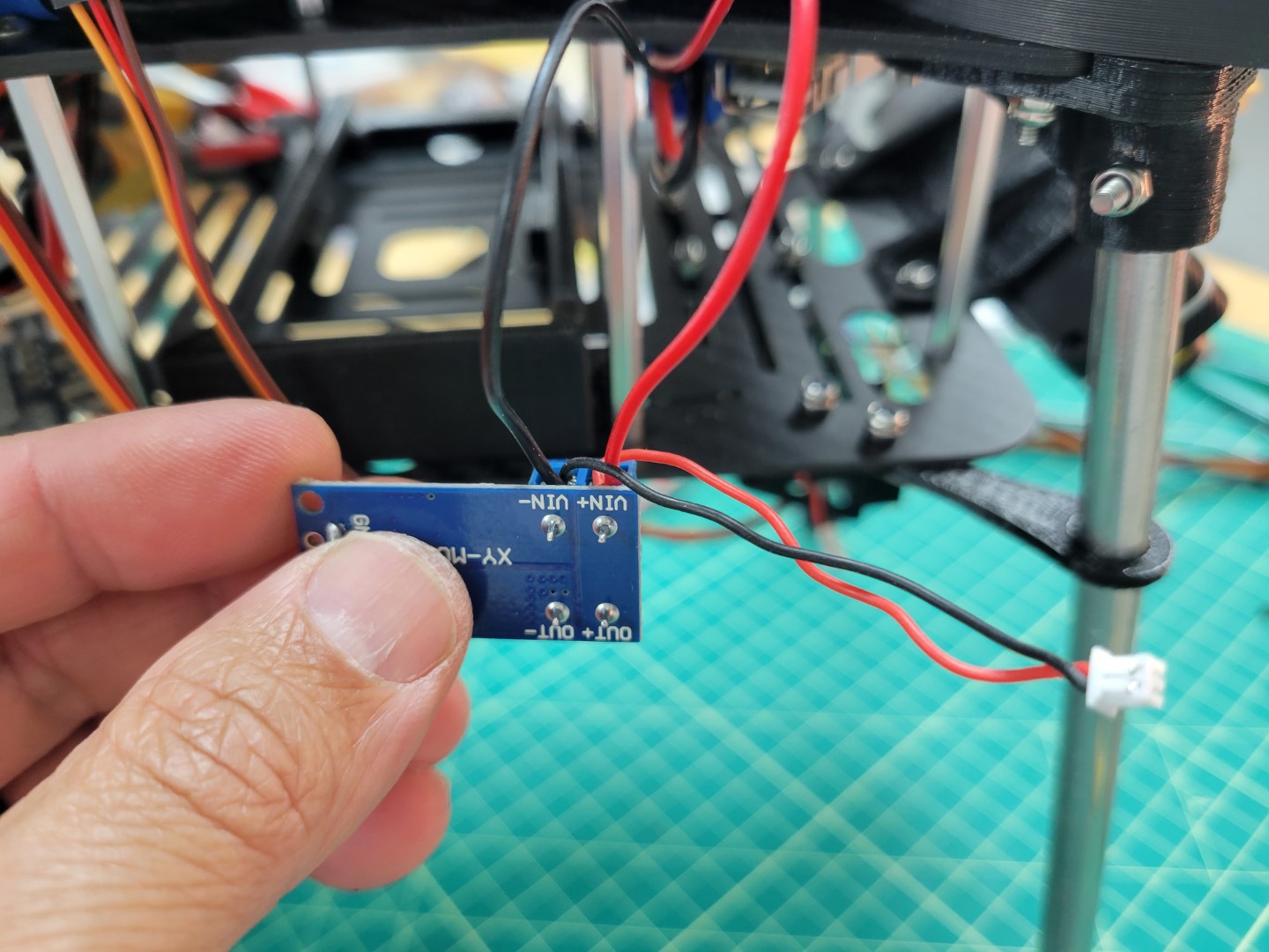
MOSFET Power Supply
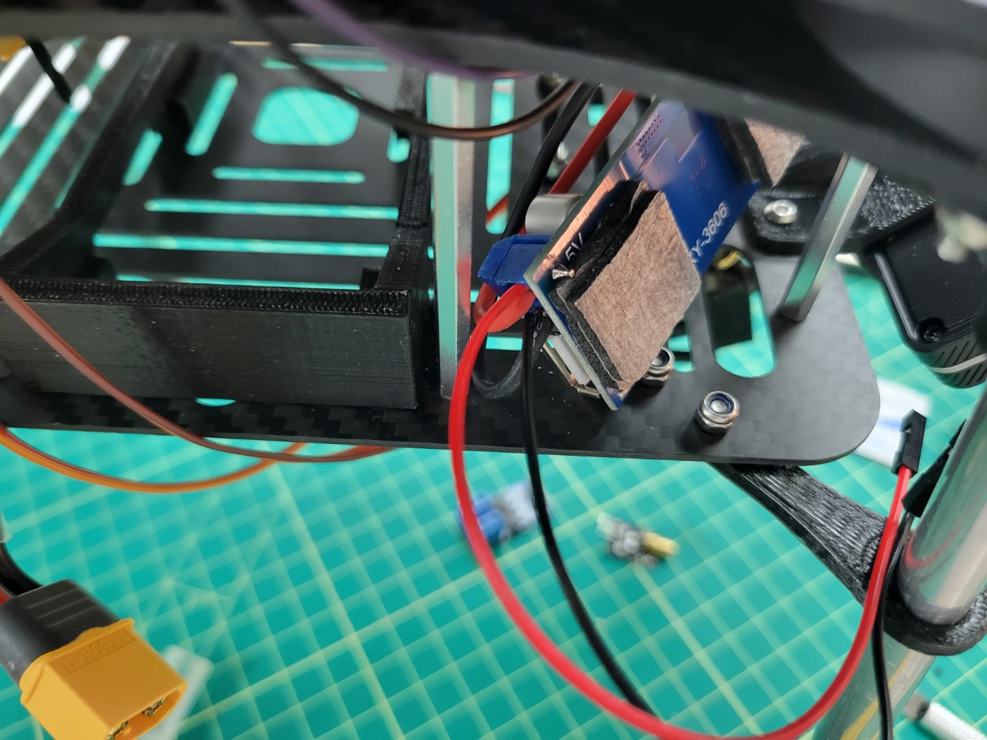
Stack 2 layers of 3M double sided tape on the MOSFET as shown in the following photo.
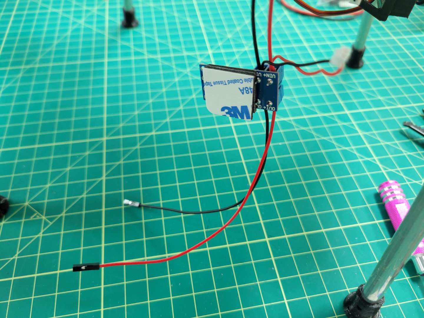
MOSFET Mounting
Next mount your MOSFET and plug in your FPV camera.
MOSFET Mounting Location
Wire MOSFET from the PCC. Wire A4 will run to the PWM. The Ground pin will run to GND.
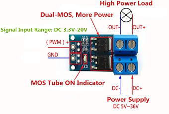
MOSFET Diagram
MOSFET Wiring
Cut and strip one side of a black and red Female-Female dupont jumper wire to approximately 8" in length. Screw wires in to their respective terminal blocks. Place the black and red wire on the ground and signal pins of the laser pointer respectively as shown in the following photo.
Laser Wiring
Thermal Camera
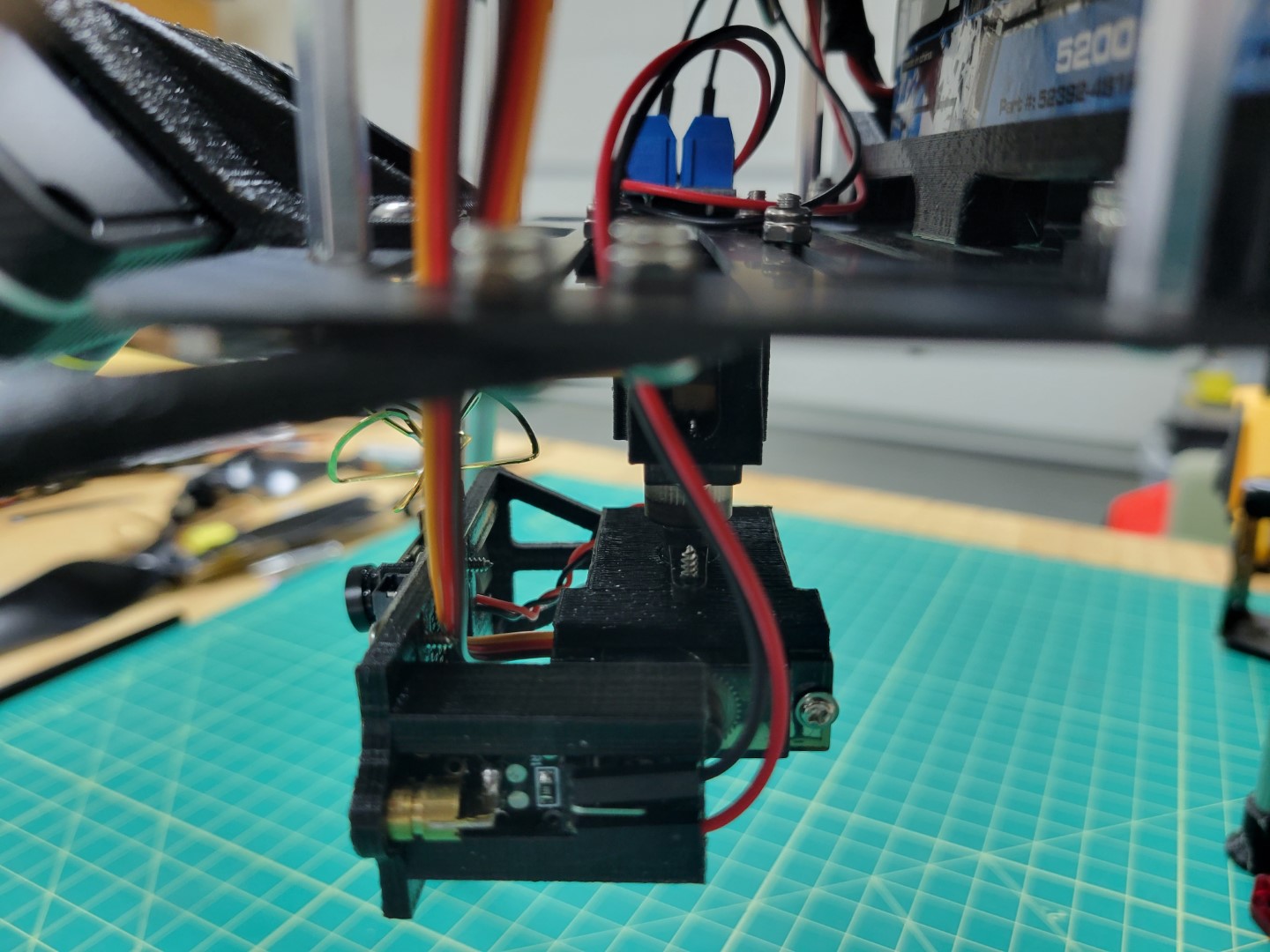
Locate the thermal camera JST SH 4-pin connecting cable and four 12" jumper wires with corresponding colors from your kit.
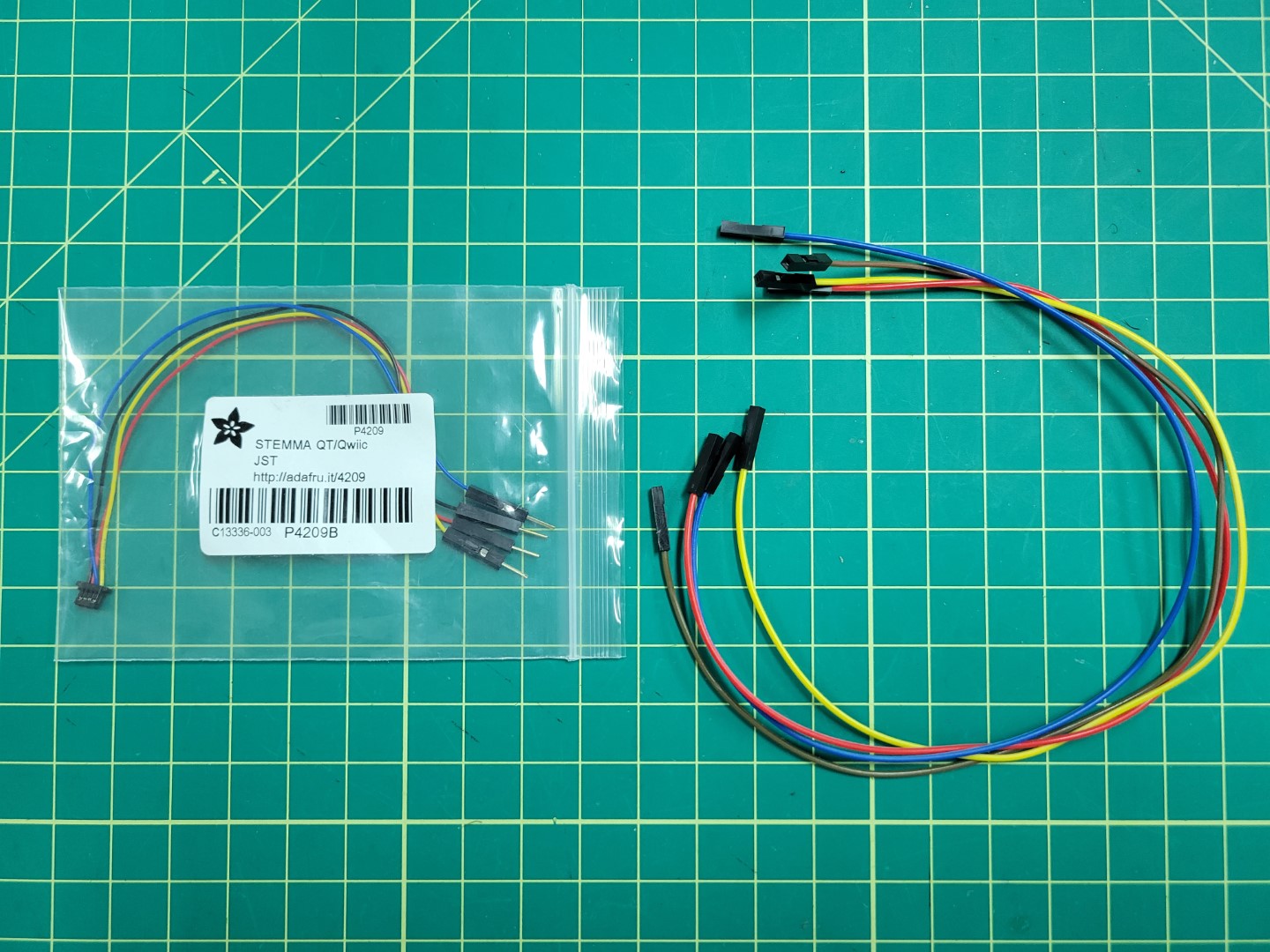
Thermal Camera Wires
Connect long female-female jumper wires of corresponding colors. It may be beneficial to add a little bit of electrical tape to ensure they do not come undone.
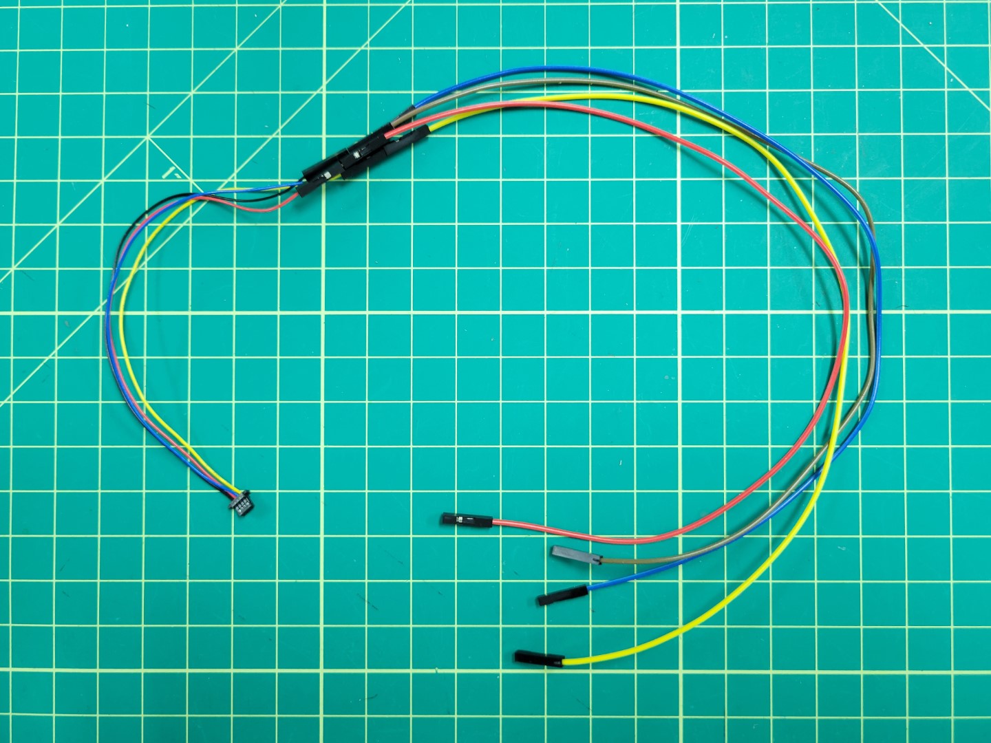
Thermal Camera Wiring
Remove your plastic end pieces.
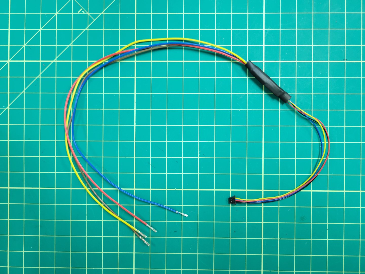
Thermal Camera Bundle
Attach the JST connector to the thermal camera and route the cables through the top accessory plate.
Thermal Camera Connection
Place your top cables into the 20x2 connector housing on your Jetson per the following wiring diagram.
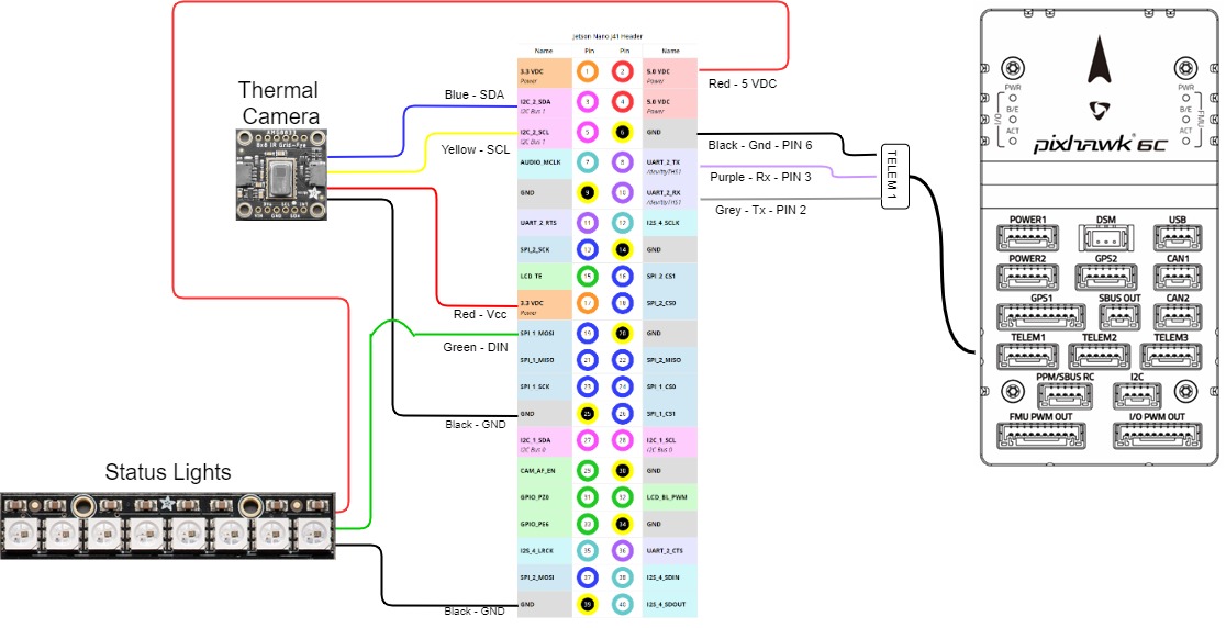
Jetson Pinout
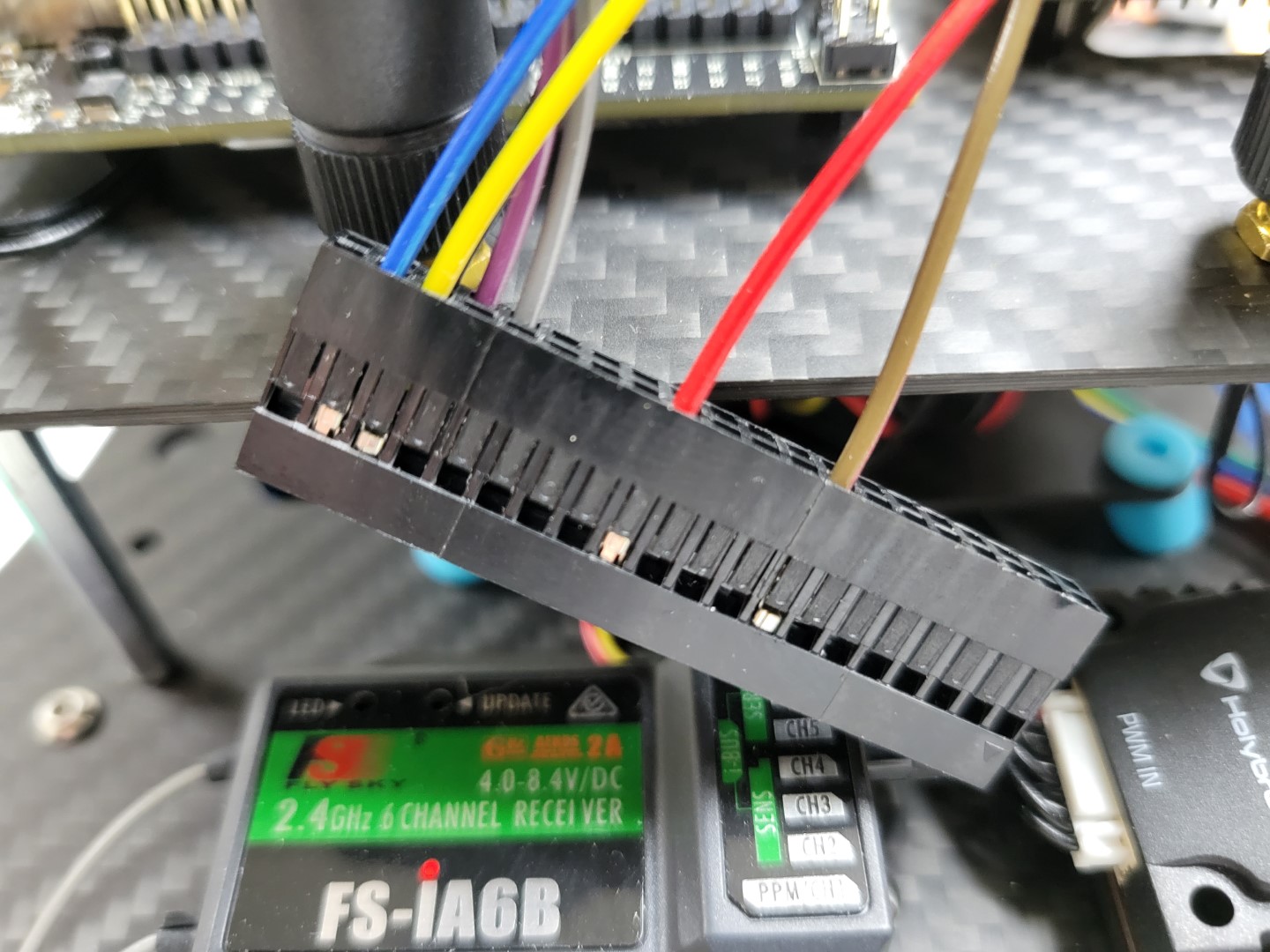
Thermal Camera 20x2 Connector
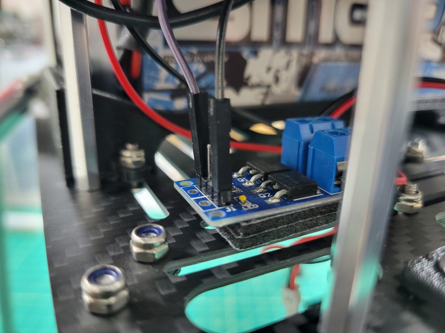
The final product should look like the following.
Thermal Camera Wiring Overview