FC to ESC Wiring
6 minute read
FC Wiring
Note
This section of the build requires some additional tools not included in your AVR kit such as a soldering iron, heat shrink tubing, wire strippers, and a hobby knife.
You may have noticed that the ESC has a connector with several flying leads coming out of it. These leads are what we will be connecting to the FC. The FC will send PWM (Pulse Width Modulation) signals to each of the motors to keep the AVR drone hovering in the air.
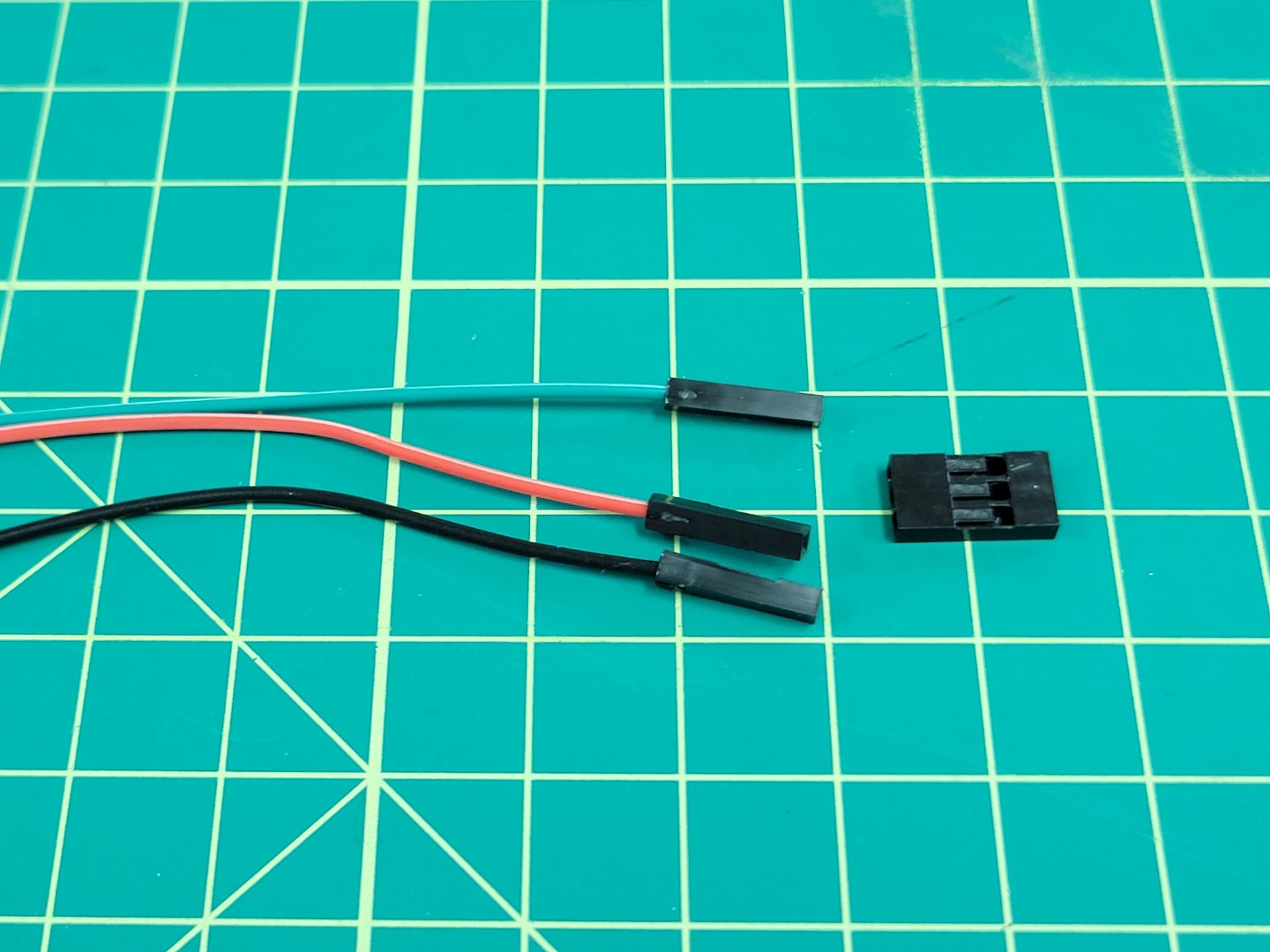
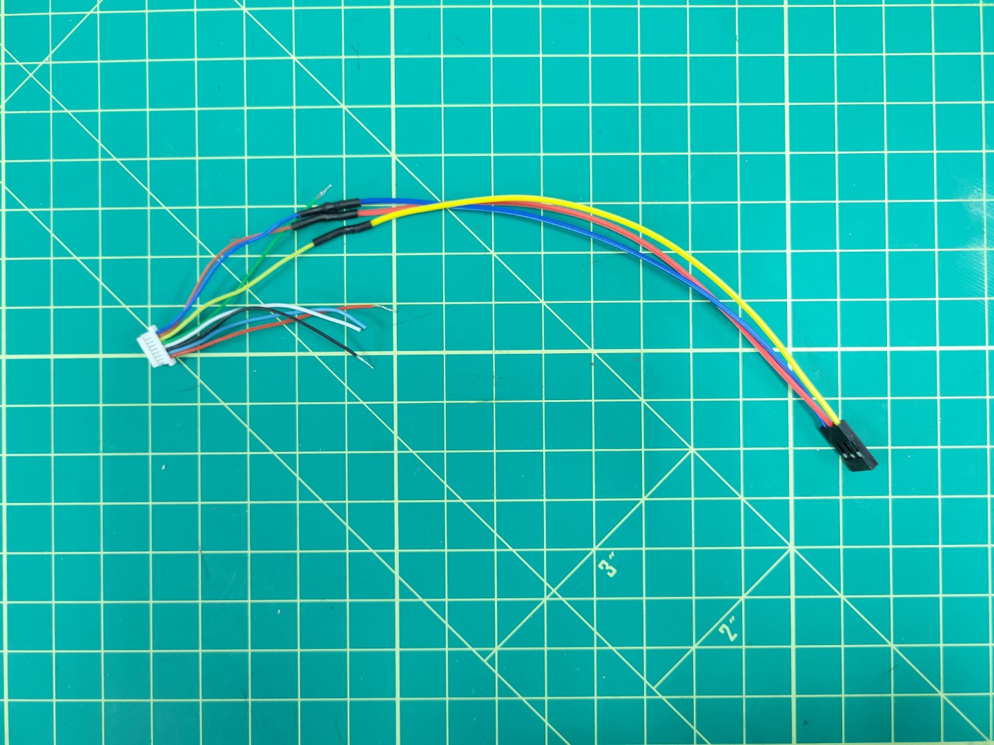
Remove the small white cable adapter from the ESC and gather the necessary parts for this phase of the build as seen in the photo below.
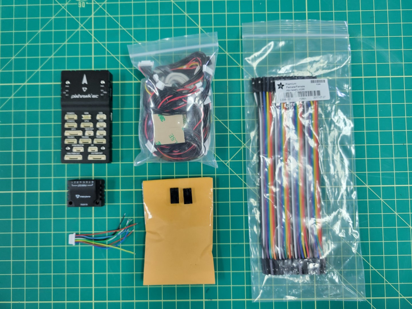
Parts for wiring FC to ESC
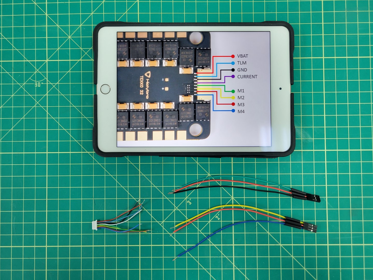
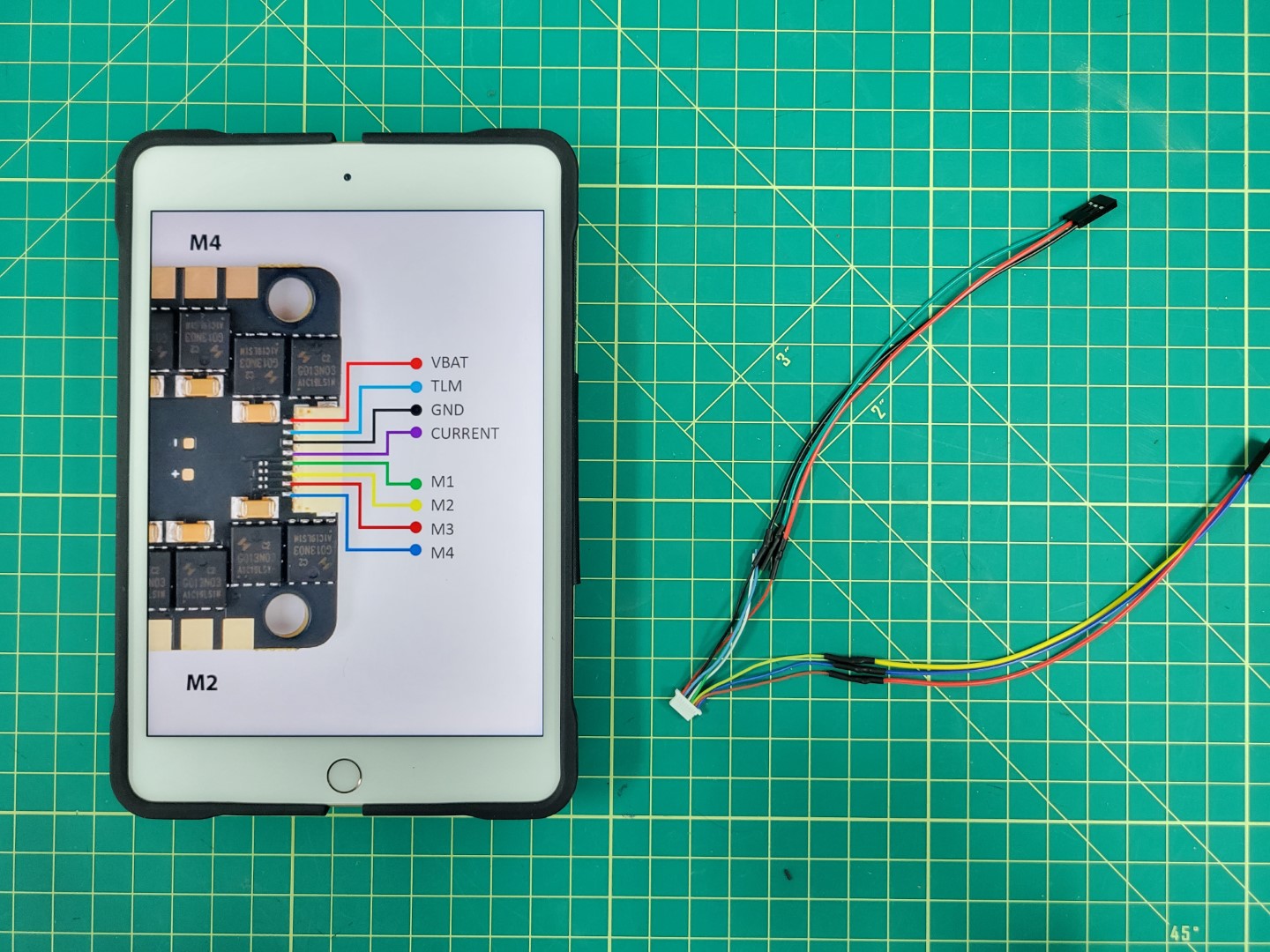
The image below shows the pinout for the ESC connector. We will be focused on wiring each of the motor leads (M1-M4) as well as VBAT and GND to the PWM module of the FC. We will not be using TLM or CURRENT.
Warning
Each of the leads has a small amount of wire exposed. Go ahead and clip off the exposed wire of the TLM and CURRENT leads.
Pull out four jumper cables from your AVR kit and to keep things simple make sure they mach up with each of the motor wire colors. They will be green (M1), yellow (M2), red (M3), and blue (M4) as seen in the image below.
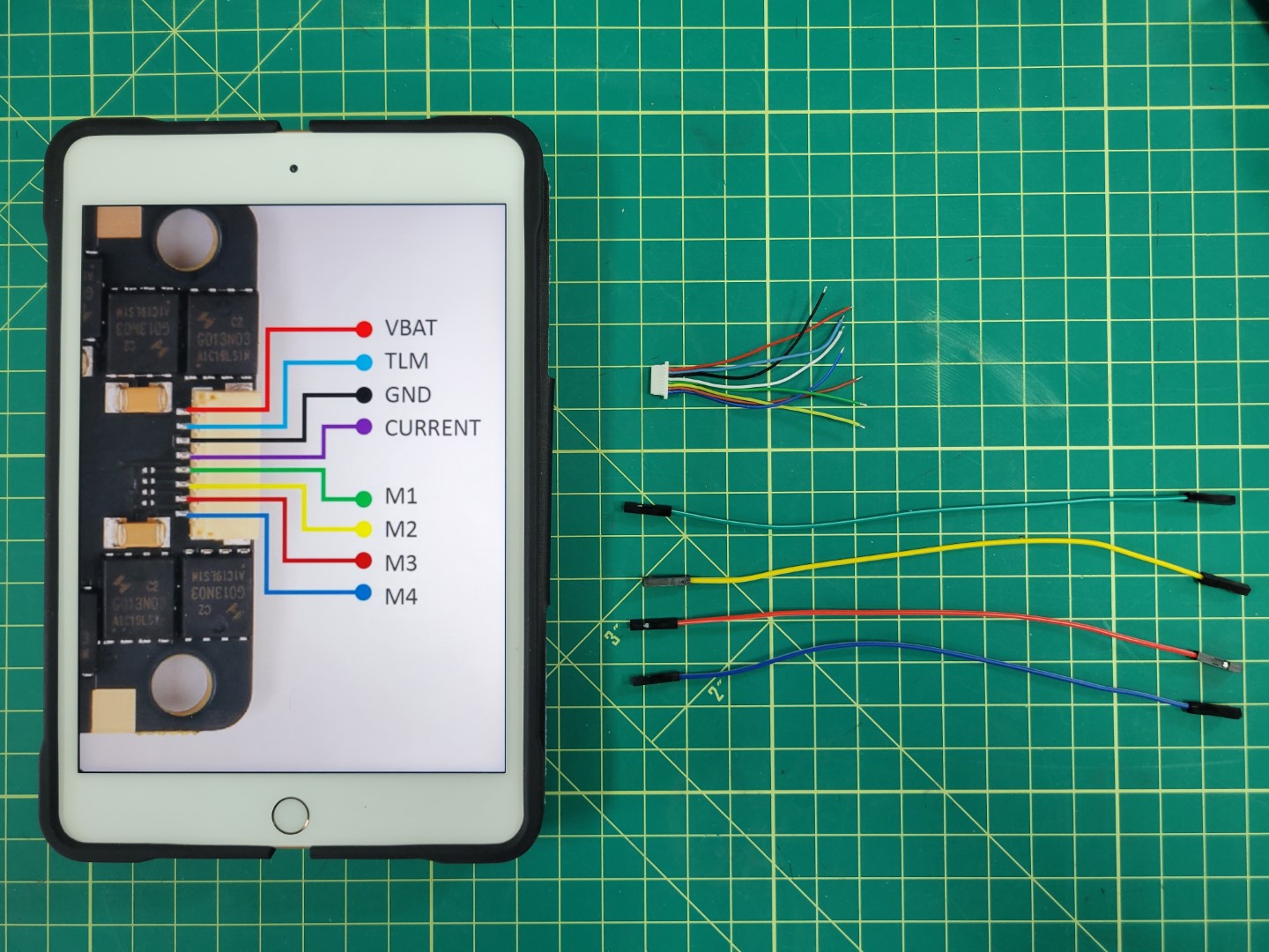
Laying out wires for soldering
Remove the plastic female connector from one end of each jumper cable. This is easy to do once you understand how the connector works. There is a small tab that you can pry up and then slide the cable out. A small flat head screwdriver or tweezers area great tools to assist with this step.
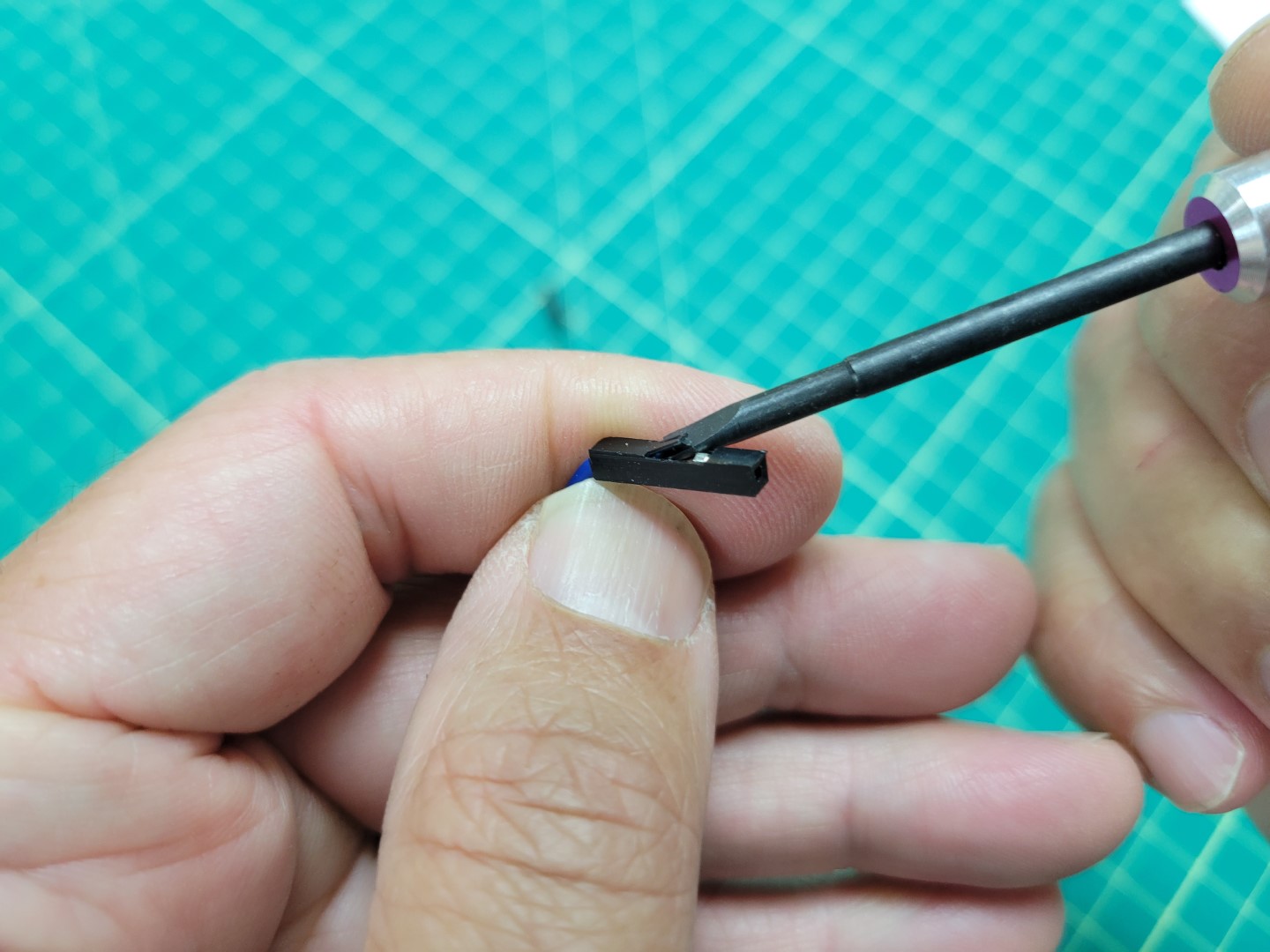
Plastic connector with tab lifted up
Slide the wire all the way out and get rid of the plastic connector.
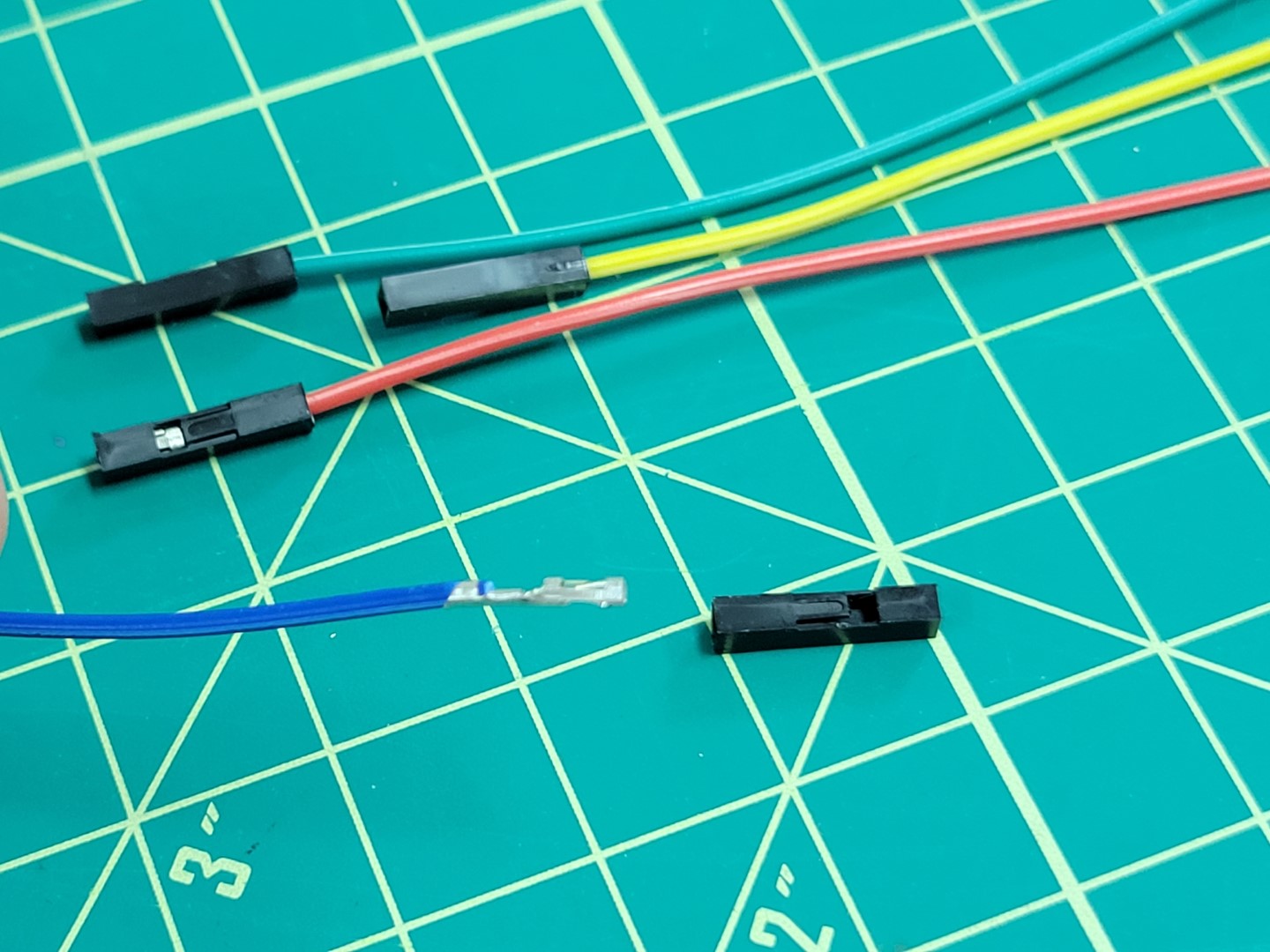
Wire removed from plastic connector
Slide the wire into the servo connector housing as shown in the photo below. Servo connectors can be found in a small envelope of miscellaneous parts in your kit. Refer back to the first photo in this section to see it.
Note
Make sure that you listen for a click sound when sliding the wire into the servo connector. Pay attention to the orientation of the wire in the photo below. When the wire is secure you can lightly pull on it and it will not come out.
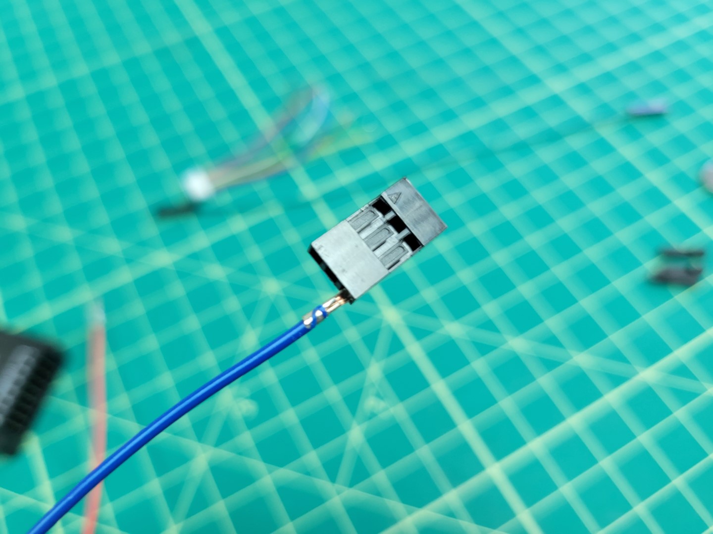
Sliding wire into servo connector
The blue wire is now secured into the connector and represents motor #4 (M4).
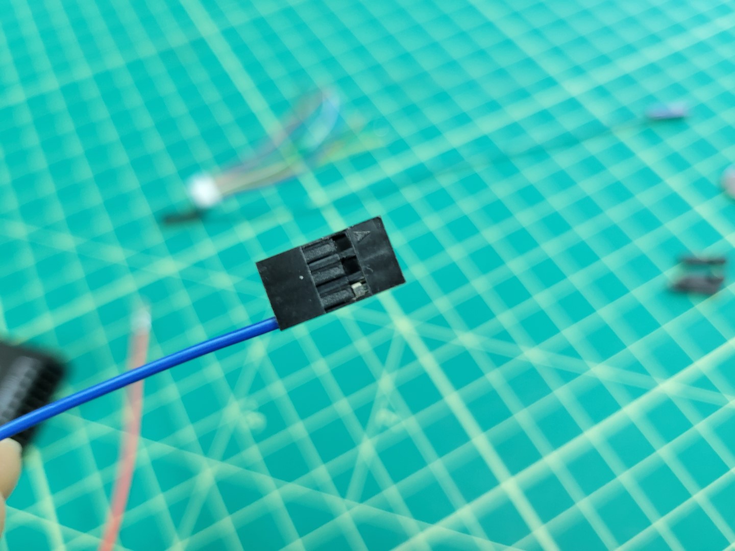
M4 wire securely in place
We will repeat this step for M2 (yellow wire) and M3 (red wire).
Warning
Motor order is incredibly important! Pay close attention to make sure your wire colors correspond with the correct motors.
The photo below shows how the cable will be attached to the PWM module from the Pixhawk. You will notice that the connector is plugged in horizontally across the top row of pins 2, 3, and 4. Pixhawk can support up to 8 motors (an octocopter) and each number represents a specific motor.
Tip
If you look closely at the PWM module you will see S, +, - labeled on the right side. This means the top row of pins are SIGNAL pins, the middle are POWER pins, and the bottom are GROUND pins.
M2, M3, and M4 connector
Let’s repeat the same process for M1 (green), VBAT (red), and GND (black). You will remove each of the plastic female connectors and secure the wires into the servo connector.
M1, VBAT, and GND wires
Once again, pay attention to the ordering of your wires. Your second cable should look identical to the one below.
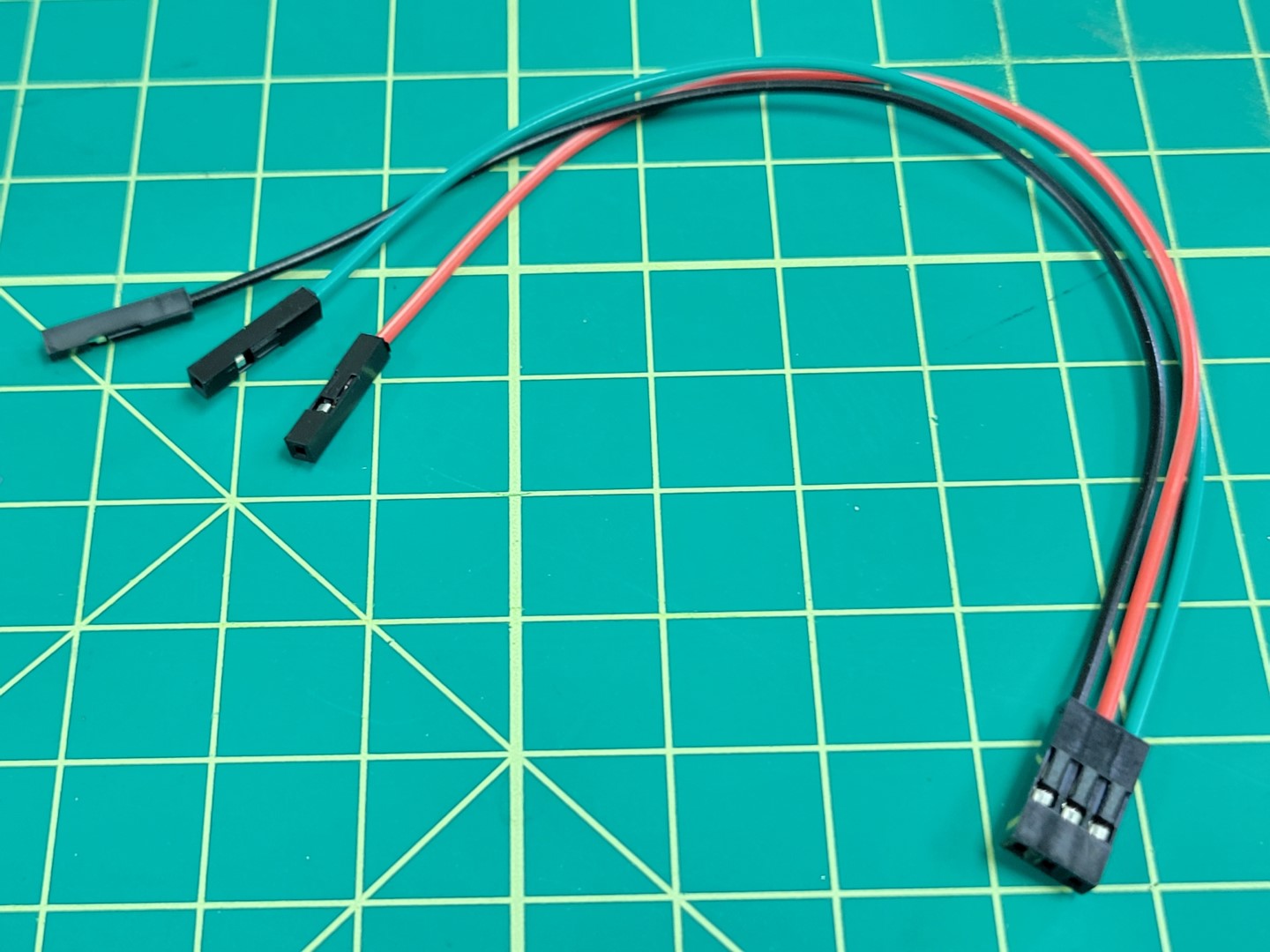
M1, VBAT, and GND in servo connector
Make sure your cables are plugged into the PWM module as shown below.
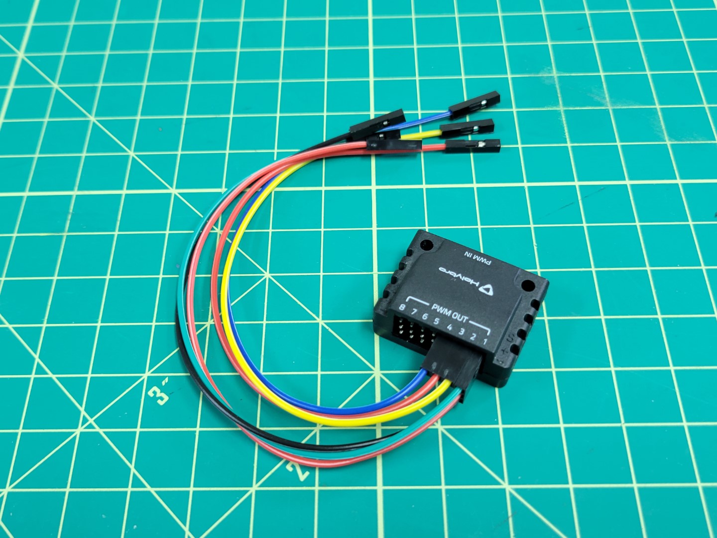
PWM module wired up
Here is a close up of the connections. This represents the FC side of the wiring. Now we will proceed with the ESC side.
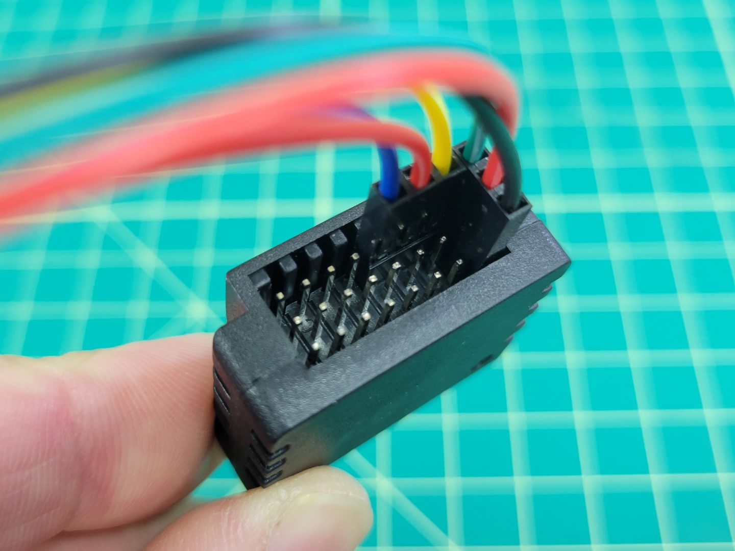
PWM module close up
ESC Wiring
Go ahead and unplug your cables from the PWM module. Let’s take one last look at the ESC side connections before we solder.
Use wire cutters to cut off the plastic female connectors from the other end of the colored leads. Proceed with stripping off about 1/2" of the wire insulation.
Remove about 1/2" of insulation from the ESC leads. You will notice that the ESC leads already have some wire exposed.
Tip
The ESC leads are very thin. We have found it easiest to pinch with your fingernails and pull the insulation away. Use caution as you do not a lot of spare wire on the ESC side!
Match up the wire color on the FC side with the same color on the ESC side. Twist the wires together using the “Twisted Helix” method described in the video below.
Warning
Don’t forget to add heat shrink tubing before twisting your wires together! The heat shrink will be necessary to keep the connections from shorting after you solder.
The photo below shows the blue M4 wire from the ESC connected to the M4 wire of the FC. The wires are secured using the “Twisted Helix” method.
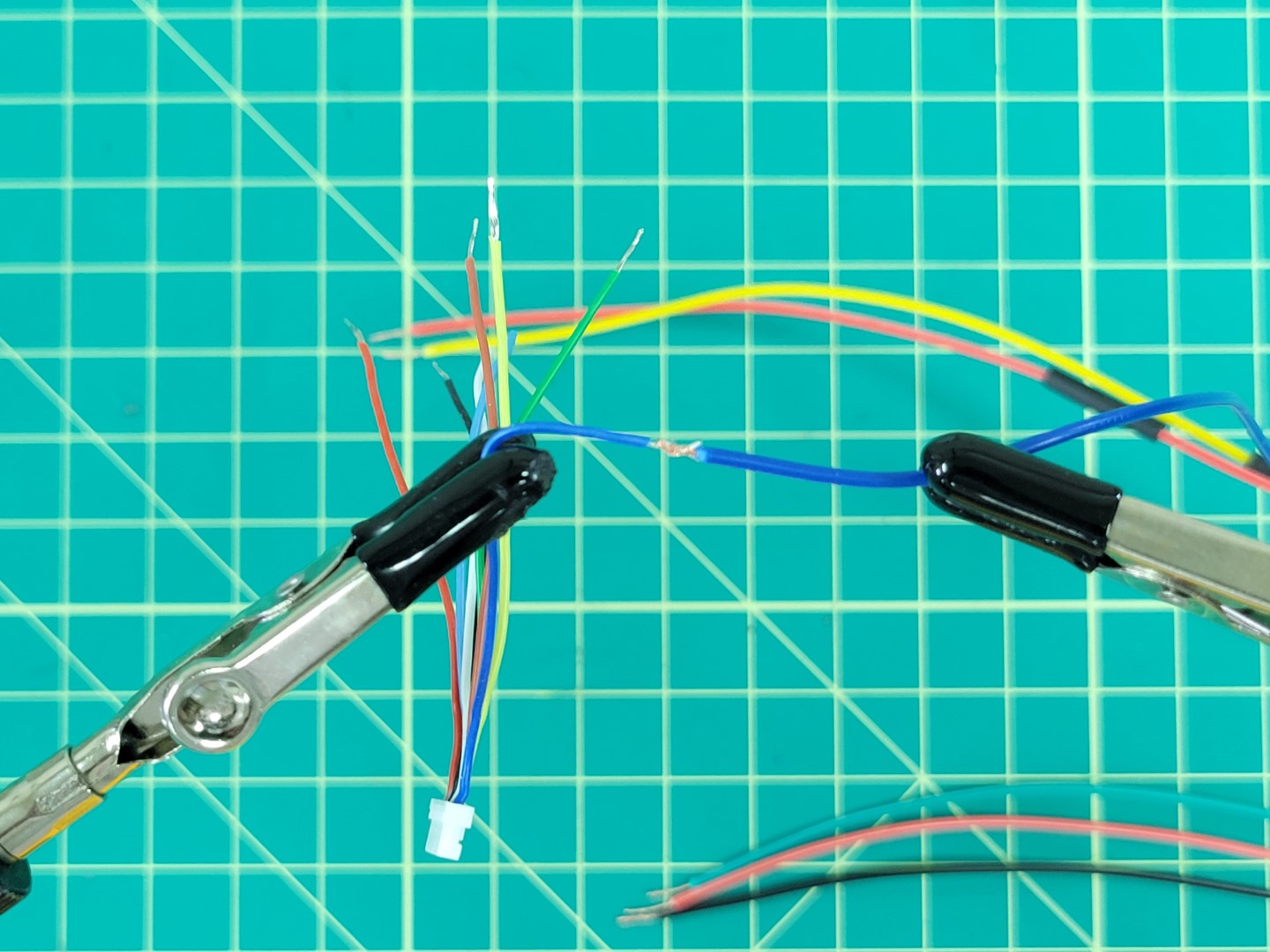
Wires twisted and ready for soldering
Tip
A helping hands device makes the soldering process 100x easier. Whatever method you use take care not to pierce the insulation of the wires. You can see in the photo below our alligator clips are covered with rubber shields.
Place solder all around the joint to strengthen the connection.
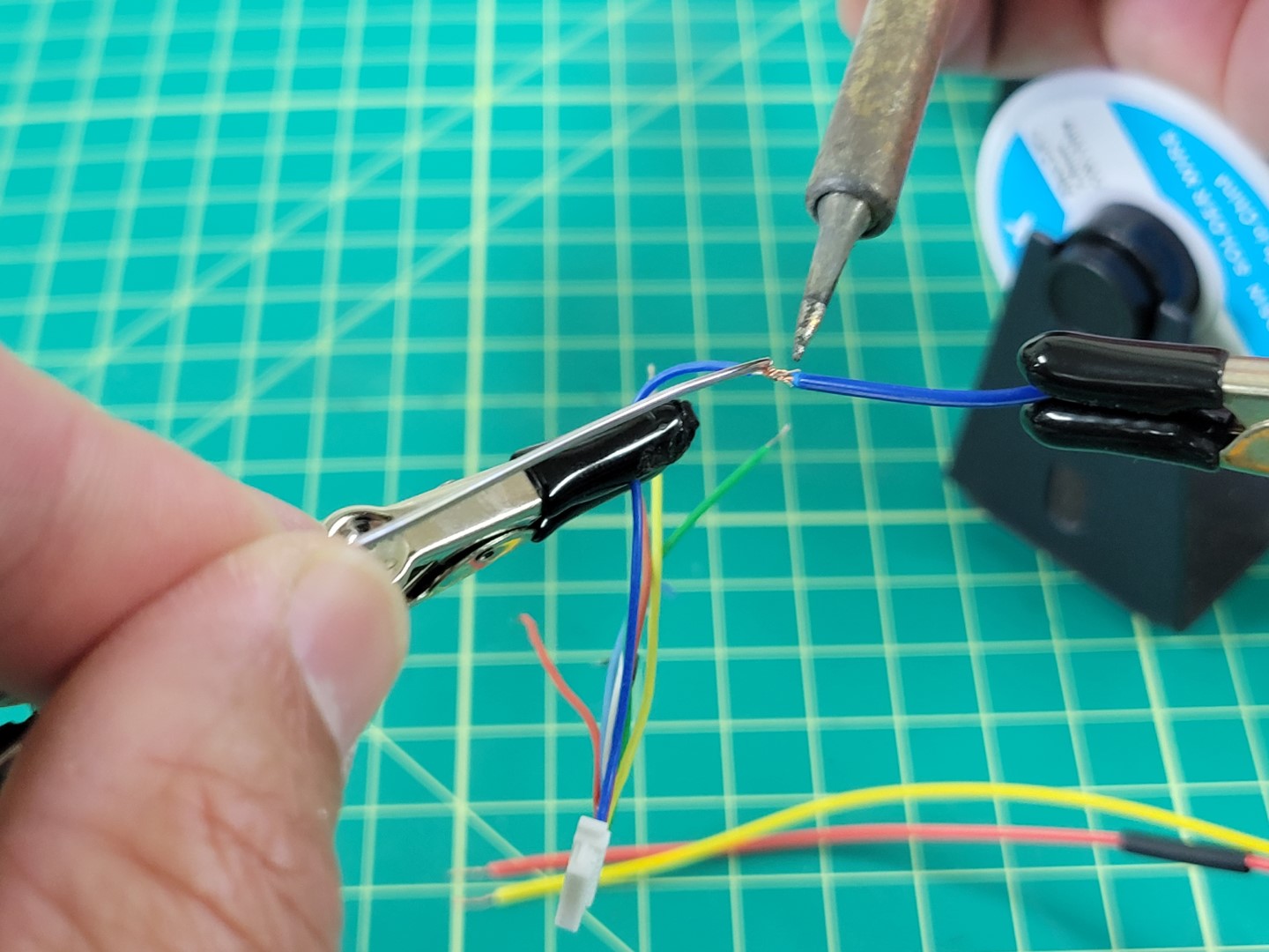
Soldering the ESC and FC M4 wires together
A little solder will go a long way. Don’t overdo it as you will need to slide the heat shrink over the joint next.
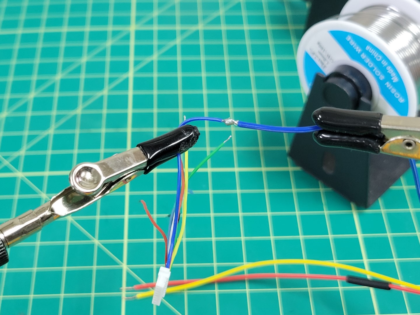
M4 wires soldered together
Slide the heat shrink over the connection and apply heat to it using a heat gun or a lighter.
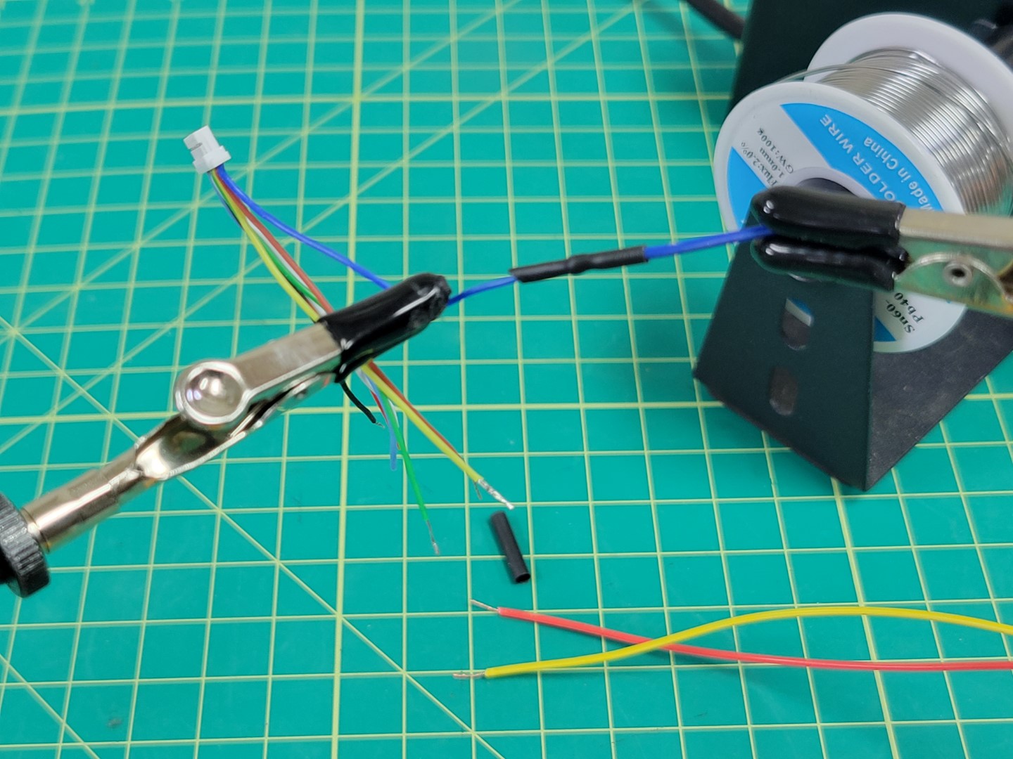
Heat shrink applied to M4 wire
Repeat this process for the M2 (yellow) and M3 (red) wires.
Warning
Red wire was used for both M3 and VBAT. Make sure not to get these wires mixed up!
M2, M3, and M4 wires soldered
Repeat the soldering process for M1 (green), VBAT (red), and GND (black). Your new cable should look like the photo below.
Warning
One last reminder to make sure you clip the exposed leads from the TLM and CURRENT wires.
All wires soldered
Feel free to apply heat shrink over all your wires to keep things clean. If you don’t have heat shrink you can use electrical tape.
Plug your connectors into the Pixhawk PWM module as shown in the photo below.
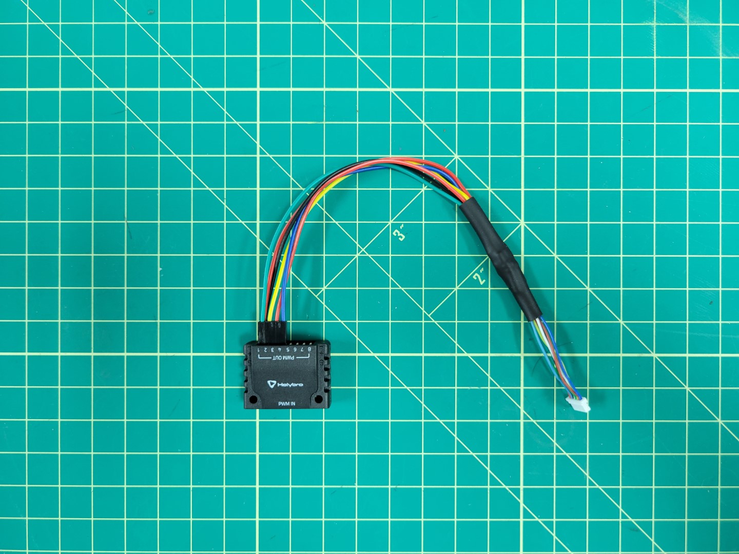
The finished FC to ESC cable
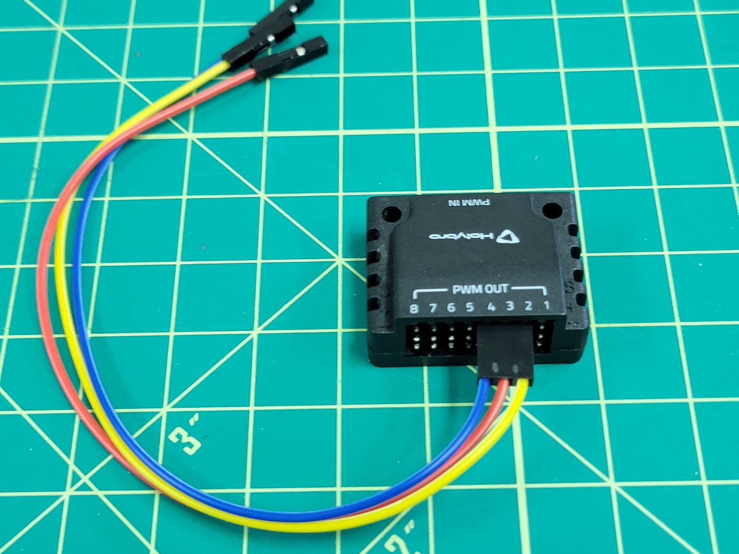
In the bag of cables that came with your Pixhawk FC look for the 10 pin connector that attaches to the Pixhawk’s I/O PWM OUT port and the PWM IN port on the PWM module.
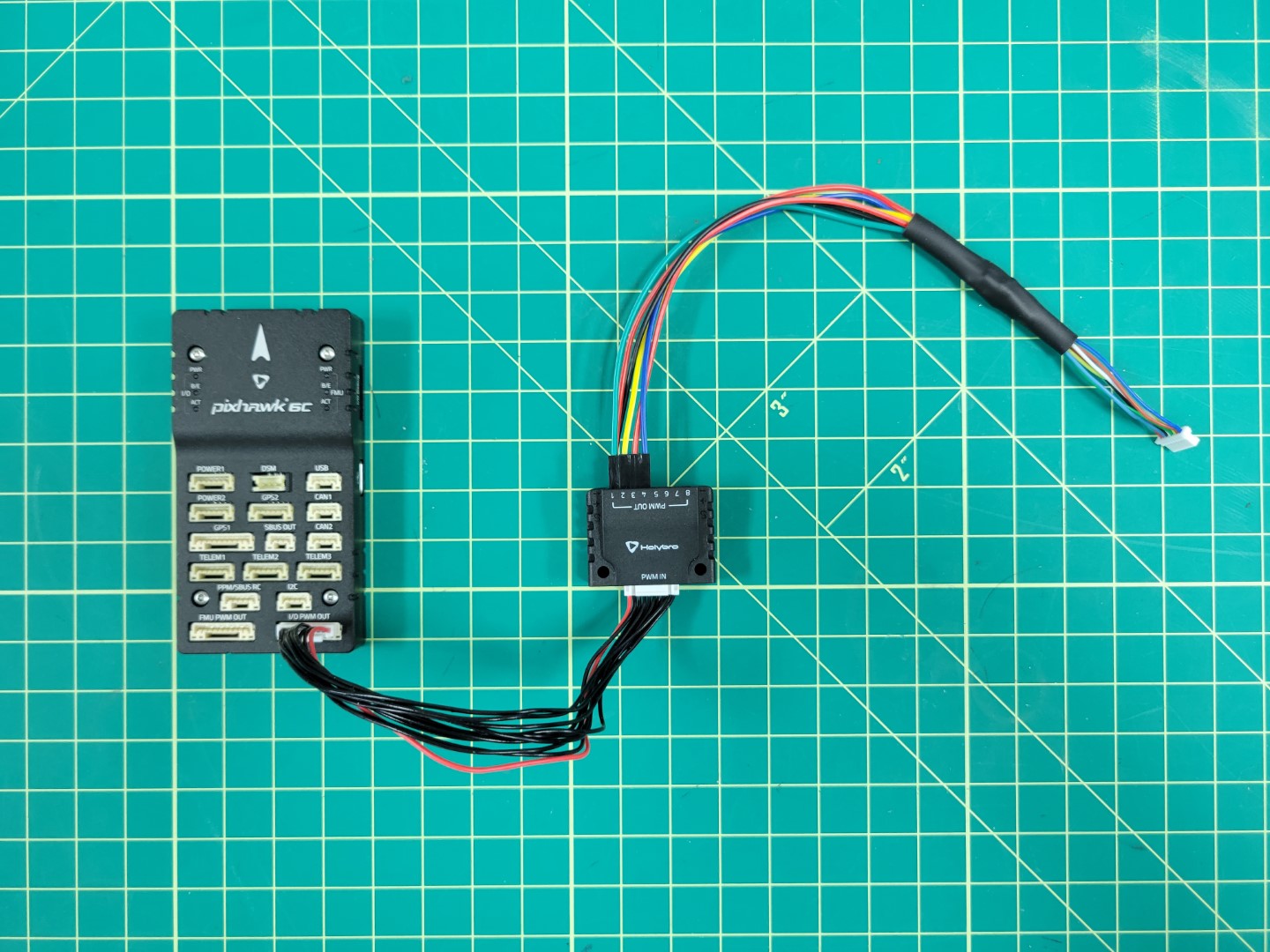
Connecting PWM module to Pixhawk
←Previous Next→