The receiver module supports up to 10 channels when using the S.BUS protocol. The first 4 channels are used for basic control with the transmitter sticks, leaving several free channels which can be mapped to auxiliary control switches. Assigning switches, dials, and buttons on the transmitter to channels can be done using the Aux. channels option under the Function tab in the Settings menu.
These channels will be useful throughout AVR and will let us do things like toggle a switch to change the current flight mode of the drone.
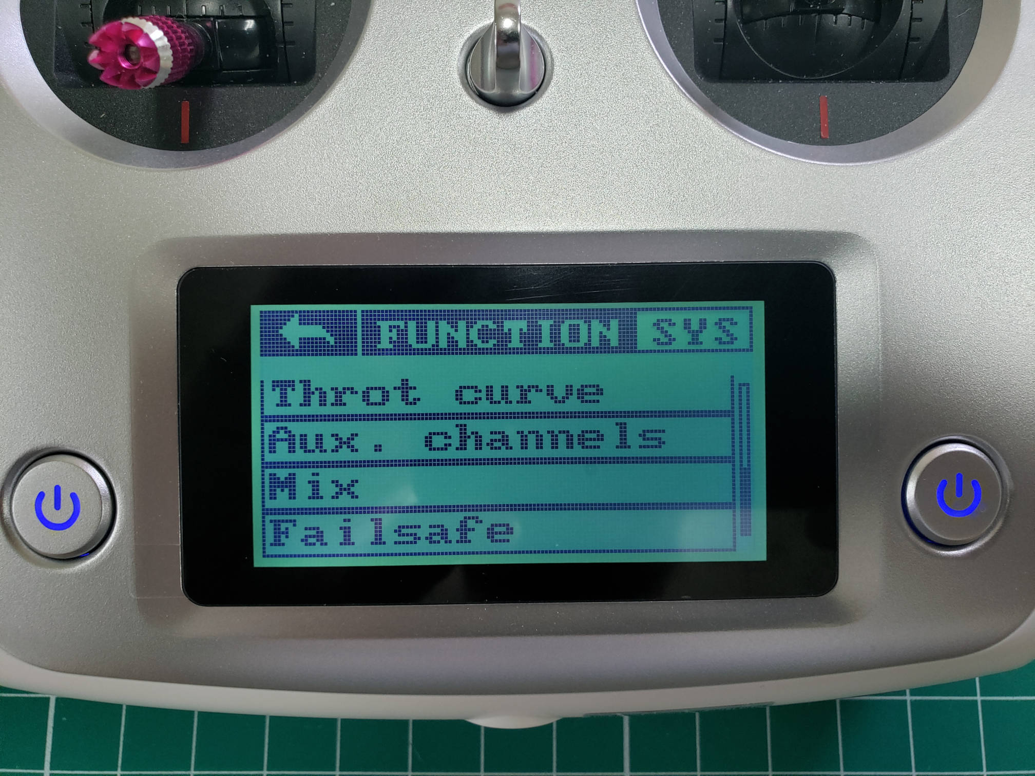
Auxiliary channels in Function menu
You can press the icon to change the kind of input (STX = stick, SWX = switch, VRX = dial, KEY = button). Pressing the text label you can specify which exact input should be mapped to the channel. It is also explained in section 6.7 of the transmitter manual.
For the AVR drone, we provide a default channel setup which allows for maximum utility of the available channels, which can be found below. In future references, we will always use the channel setup as provided here.
| Channel | Switch |
|---|---|
| 5 | SWA |
| 6 | SWB |
| 7 | SWC |
| 8 | SWD |
The following steps will walk you through assigning Channel 5 to SWA. First, tap on the big circle with the line through it.
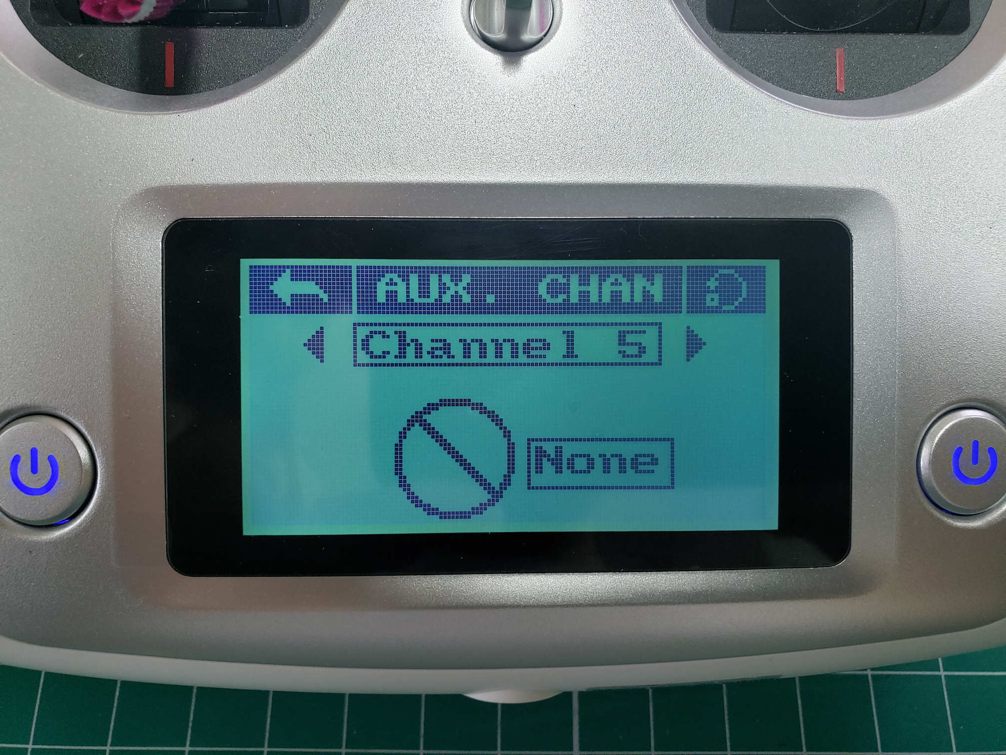
Channel 5 setup
The following screen allows you to assign CH5 to a switch. You will select SWx.
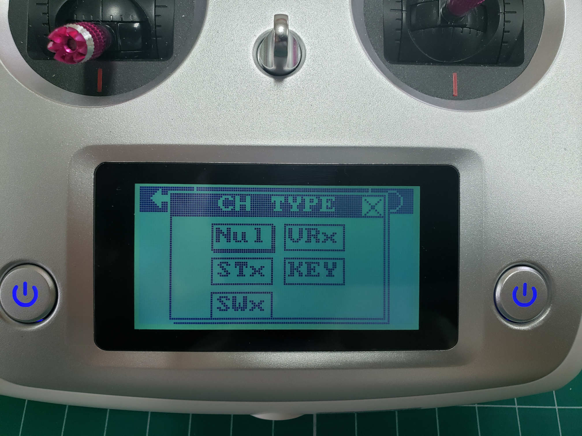
Assigning a channel to a switch
After selecting SWx you will be presented with a screen that lets you select one of the following switches: SWA, SWB, SWC, or SWD for Channel 5. In this case, we will select SWA.
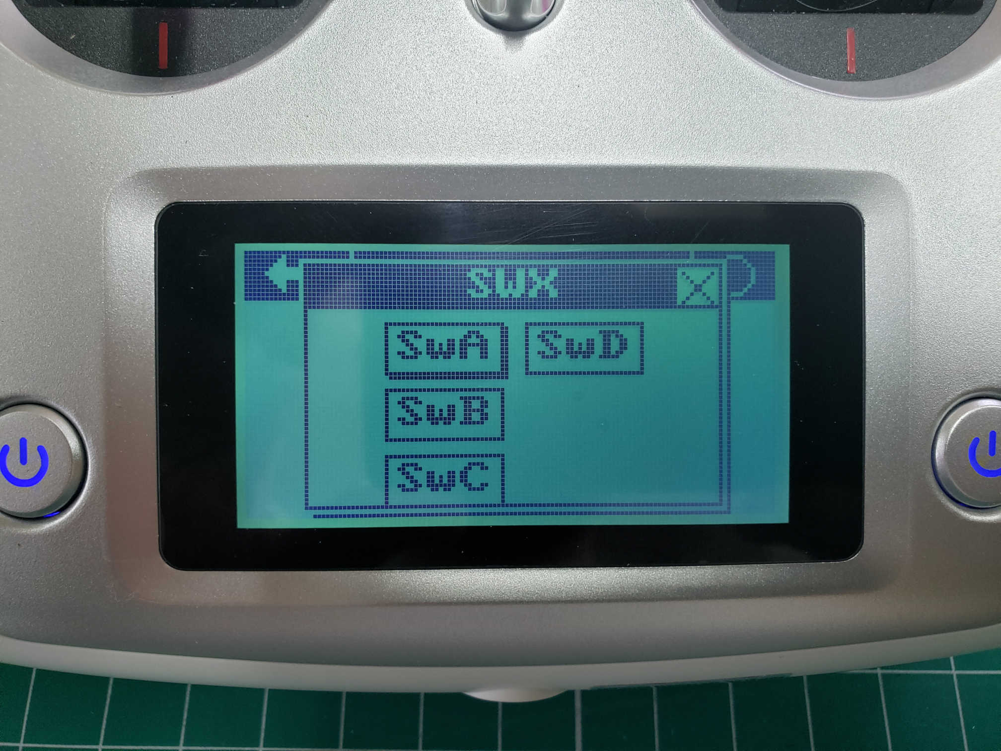
Select SWA for Channel 5
Repeat these steps for CH6, CH7, and CH8 based on the table above. After completing the steps you can go back to the home screen and swipe right to see your channel outputs. Swipe down to see CH5 - CH8 outputs. With all switches in their default position (up) you should see the output as shown in the image below.
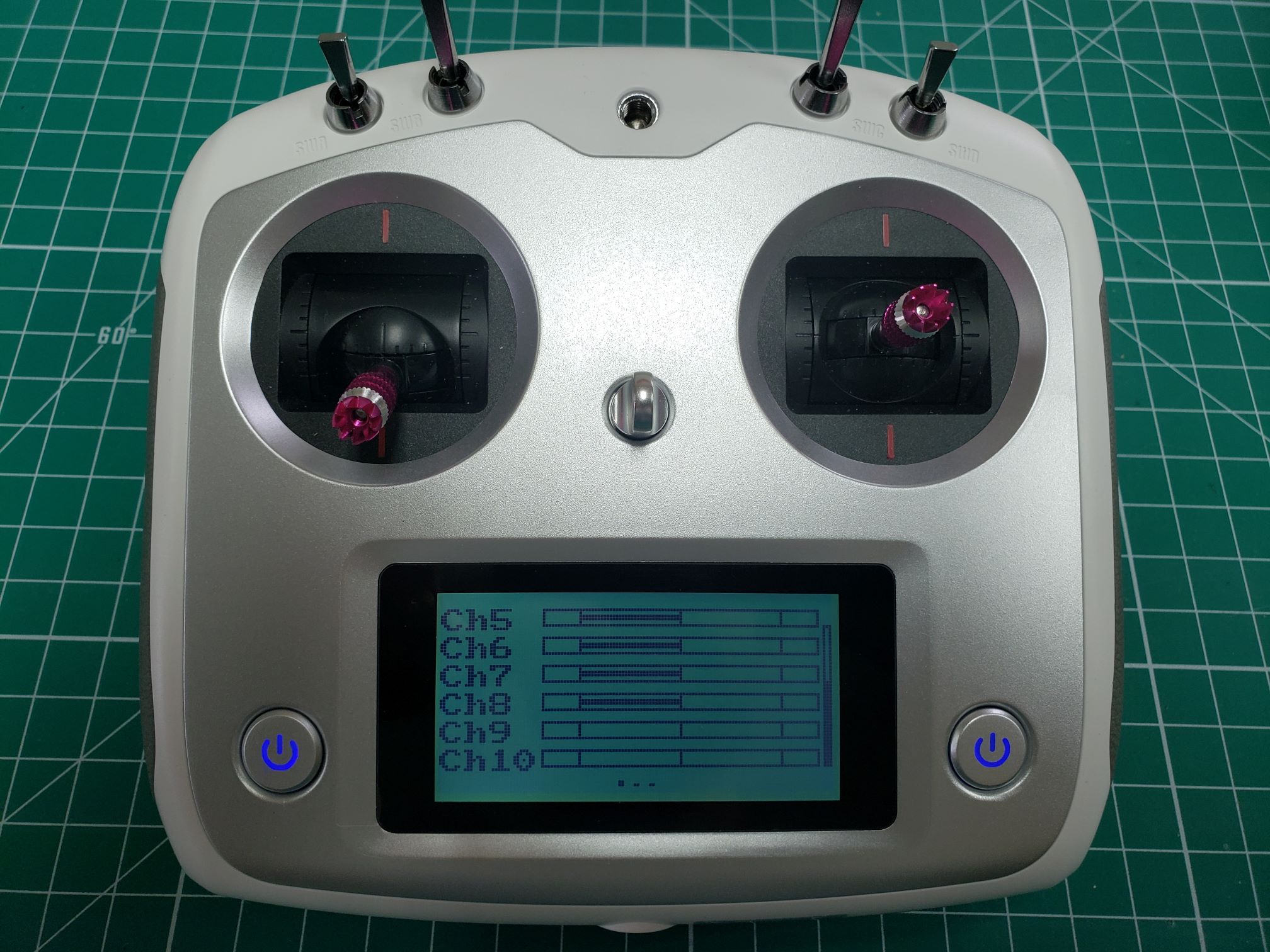
Default output for CH5-CH8 - all switches up
Now toggle all of your switches to the downward position. You should notice that the output changes and should be identical to the image below.
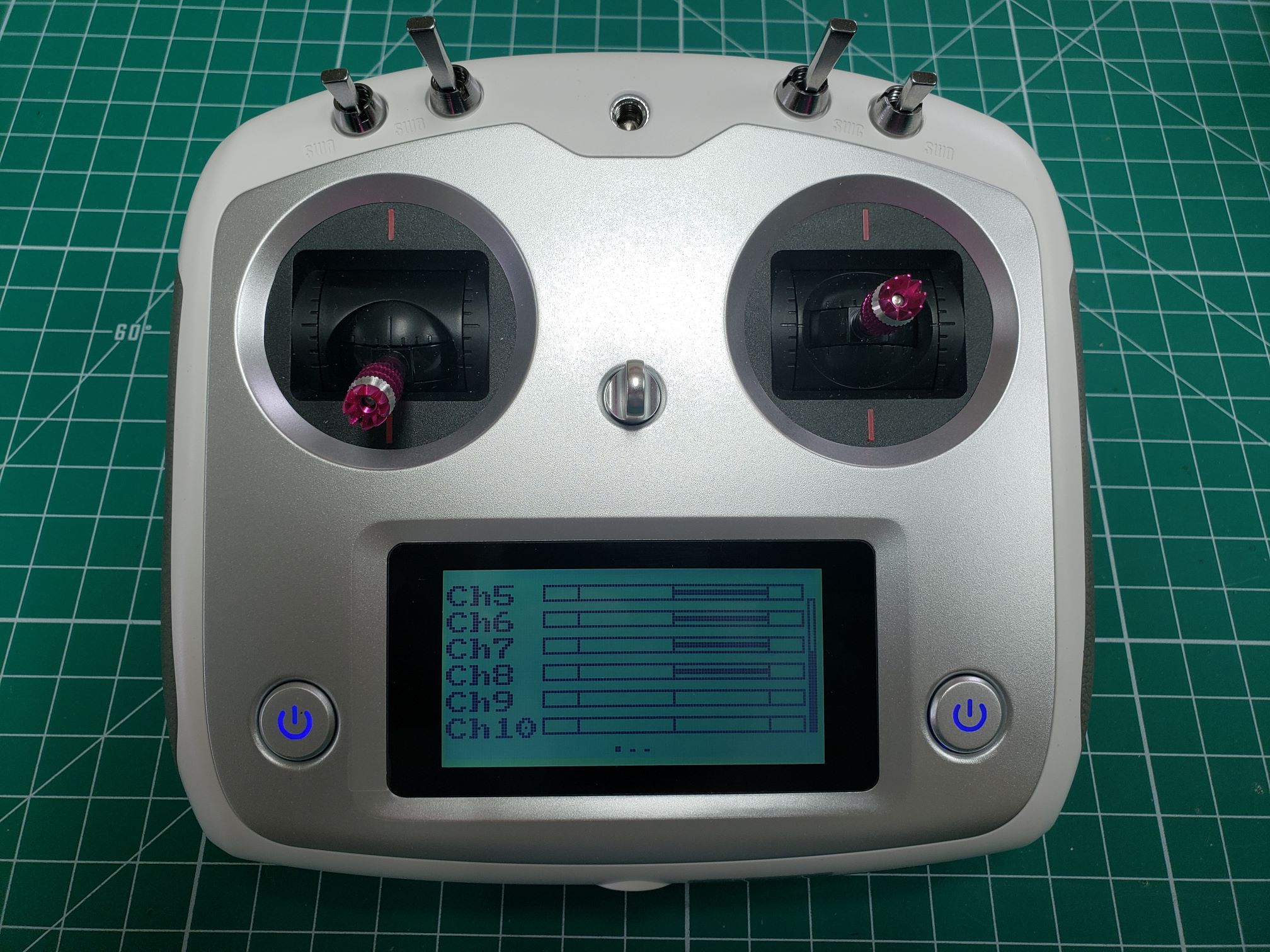
All switches toggled down