Physical Assembly
8 minute read
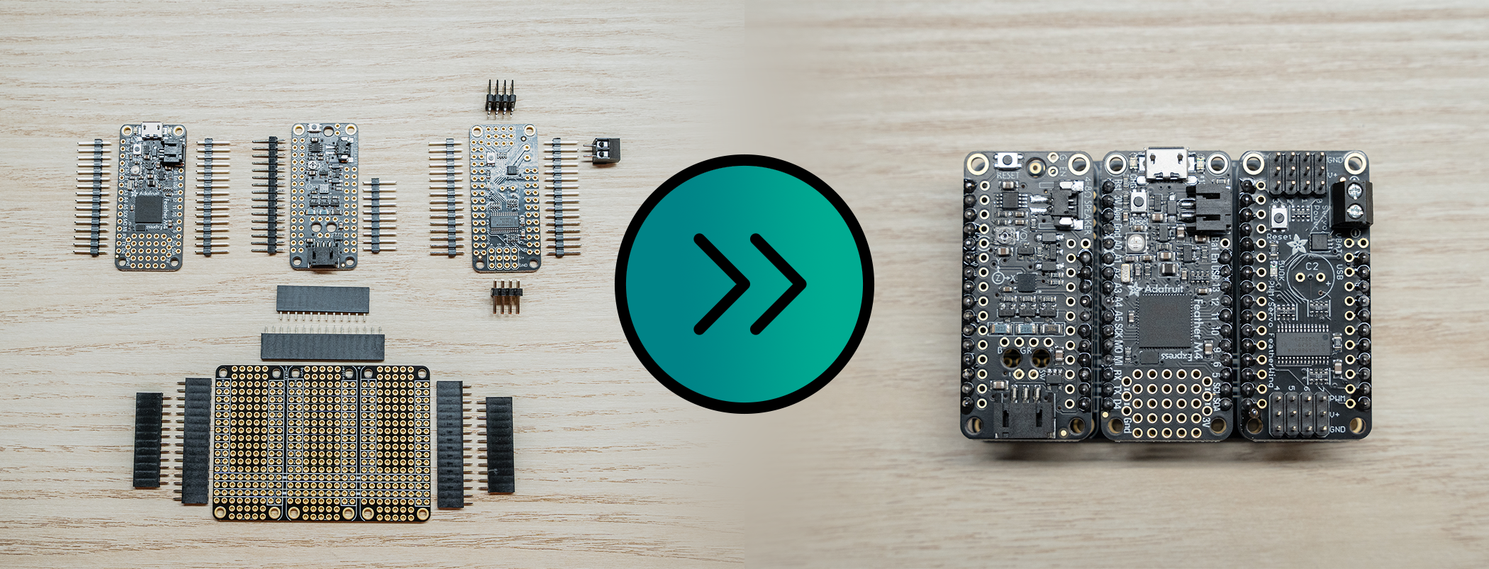
Assembling the Peripheral Control Computer is fairly easy, and just requires a bit of soldering.
Tools Needed
- Soldering Iron (I used an iron at 450C, but the recommended solder melts around 200C)
- Soldering Iron Tip Cleaner
- Solder (Recommend 60/40 Tin/Lead)
- Wire Strippers
- Breadboard
PCC Parts - Box 5
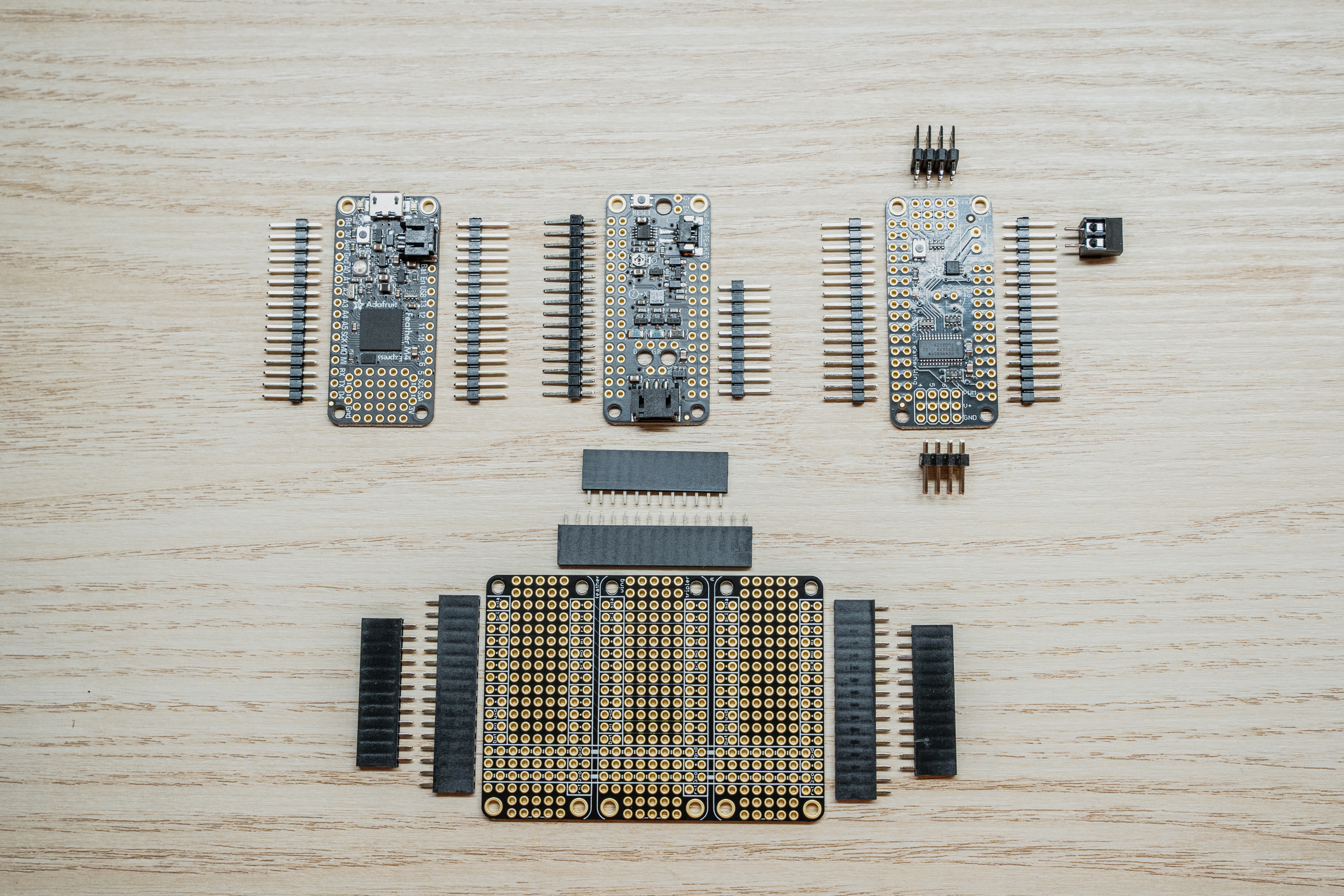
Before we get started, let’s make sure we have all the necessary parts for the PCC.
The PCC ships in 4 plastic bags consisting of the following:
- 1 x Adafruit Feather M4 Express (Pictured upper left)
- 2 x 16x1 Male Pin Headers
- 1 x Adafruit Prop Maker Featherwing (Pictured upper middle)
- 2 x 16x1 Male Pin Headers
- 1 x Adafruit Servo/PWM Featherwing (Pictured upper right)
- 2 x 16x1 Male Pin Headers
- 2 x 4x3 Male Pin Headers
- 1 x 2 screw-terminal thru-hole adapter
- 1 x Adafruit Featherwing Tripler (Pictured Bottom)
- 3 x 12x1 Female Pin Headers
- 3 x 16x1 Female Pin Headers
Note
The picture only has a 9 pin header for the Prop Maker, because mine broke off in shipping. Don’t worry this isn’t an issue, just place them together when it’s time to solder.Solder the Feather M4 Express
Before we dive in, let’s go over a couple of warnings and tips.
Warning
Soldering irons get hot… like really really hot. Pay attention to finger placement, and don’t burn yourself.Tip
The key to an enjoyable soldering experience is patience, a clean tip, and a hot iron.Step 1: Assemble Feather M4 Express
The Feather M4 is the brains of the PCC. It receives commands from the VMC and executes them in order to change the color of the LEDs or move a servo.
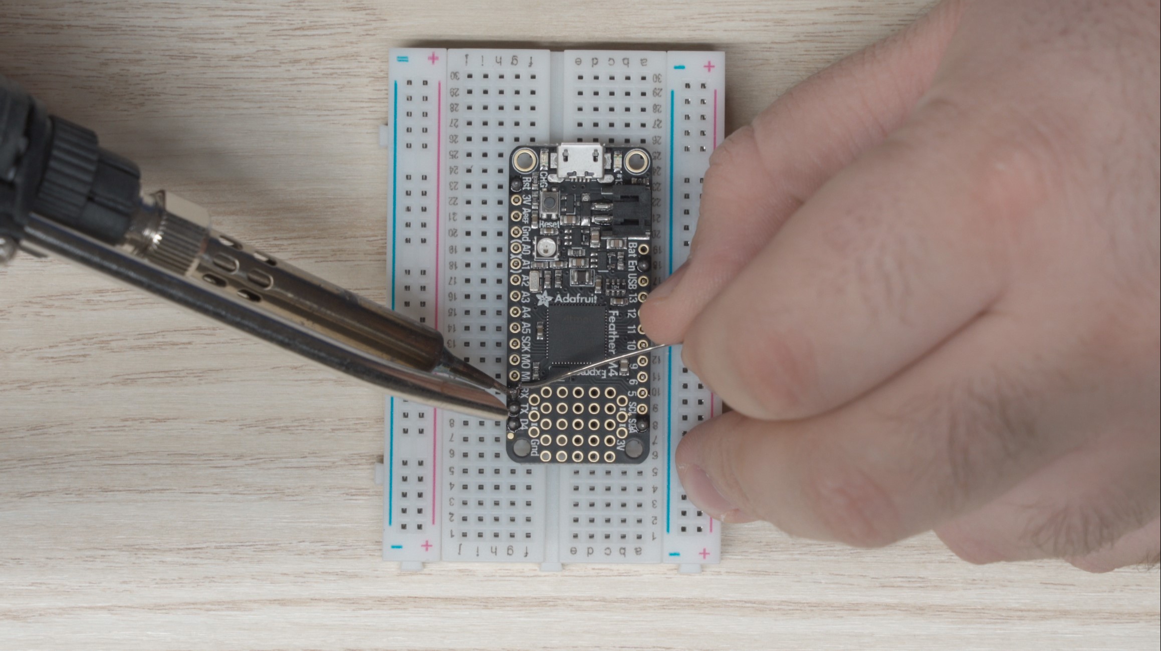
You’ll see that the M4 Express has 16 pins along its left side (assuming the micro USB port is the top), and 12 pins along the right side. Because the M4 Express ships with 2 x 16x1 headers, we need to cut one side down. You should be able to use scissors to trim one of the headers to 11 pins. Why 11? The PCC doesn’t make use of the “Bat” pin and in our testing including this pin caused issues. For this reason, we chose to omit this pin. You can see it is missing if you expand the picture below:
M4 Express being soldered
Tip
Place the headers in the breadboard, long side down to act as a fixture for soldering. It will be much easier this way.With the headers cut to length, grab your breadboard and place the headers in the “a” and “g” column as in the picture above, with the long side of the headers going into the breadboard. Make sure it’s lined up correctly and set the M4 Express onto the pins. The feather should not move around anymore and you can begin soldering.
For the smoothest outcome, start by soldering the pins in the four corners so the pins don’t move around on you when soldering the rest. I like to use a hot iron (around 450°C) with a fine tip for this.
Use the following steps to complete a solder joint:
- Place the iron tip on the feather such that it is making contact with the protruding pin as well as the donut-shaped pad that the pin protrudes through.
- If your iron is clean and hot, after about 5 seconds you should be able to move your solder in to touch the iron at the junction where the iron and the pin meet. The solder should melt almost immediately, and wick around the pin.
- Don’t go overboard with the solder. You want just enough that the solder forms a cone shape around the pin. Less really is more here.
- Pull the solder and iron away from the board and inspect your work.
- Repeat steps 1 through 4 for each pin on the M4 Express.
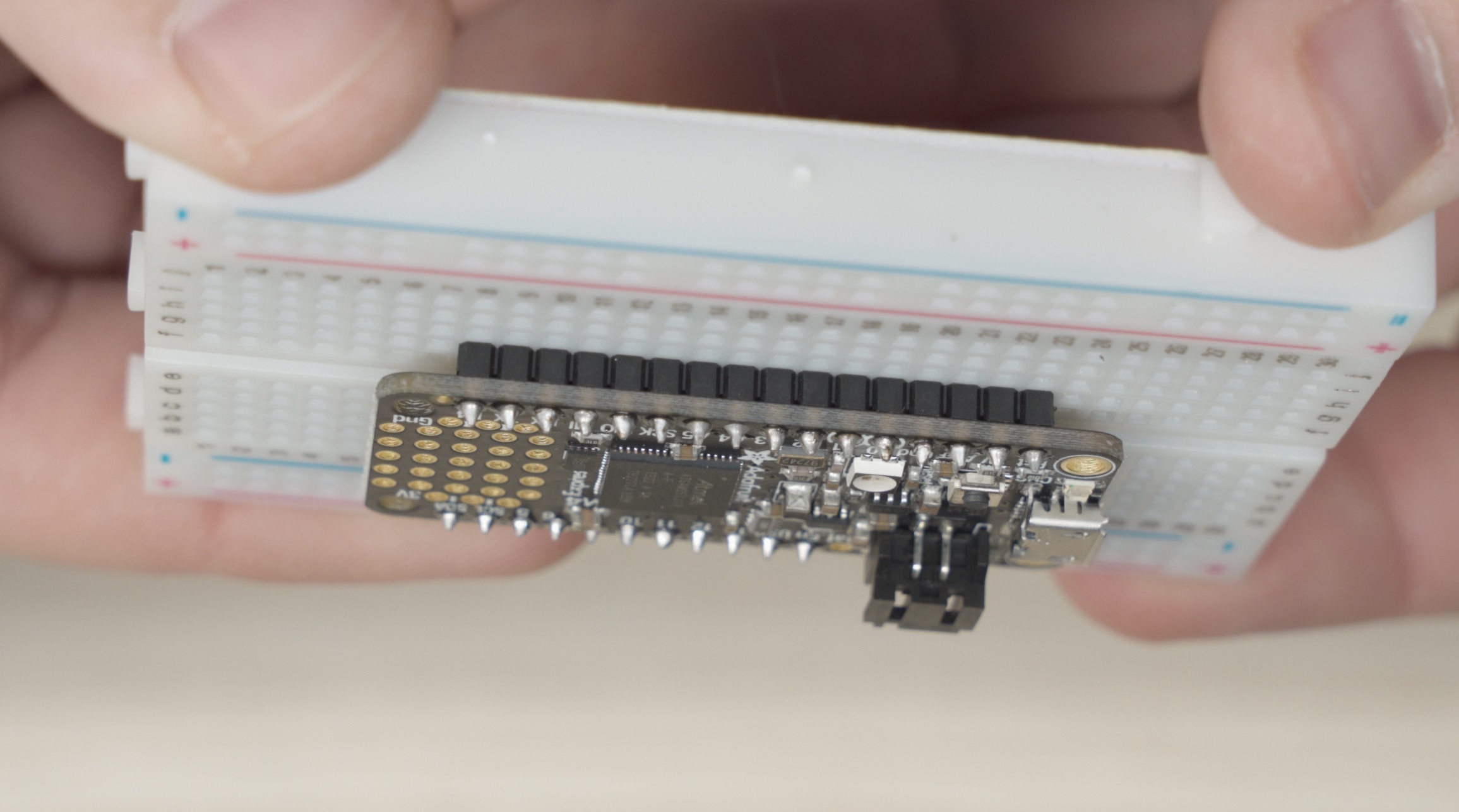
Once complete you should have solder joints that look like this:
Completed M4 Express
Once you’re happy with your soldering work, grab each end (the micro-usb and opposite side) and slowly inch the feather out of the breadboard. It is very easy to bend a pin trying to remove it so just go slow and be careful.
Tip
If you bend a pin removing the soldered part from the breadboard, use some needle nose pliers to bend it back straight. Don’t work the pin too much though, or you’ll break it.Hopefully that wasn’t too bad! Now we need to repeat similar steps for the prop maker and the servo featherwing.
Solder the Prop Maker
The steps for the Prop Maker are the same as the M4 Express.
Make sure to cut one set of male headers down to 11 pins and skip the “Bat” pinhole.
Place the headers into the breadboard and solder all the pins.
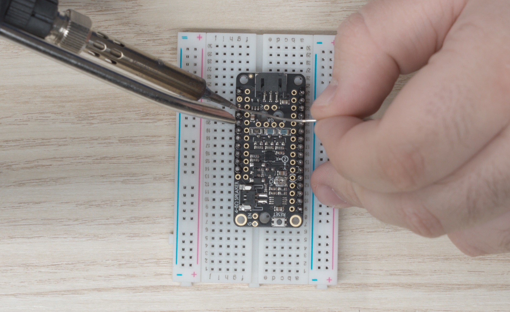
Prop Maker being soldered
Solder the Servo/PWM Featherwing
For the Servo featherwing its easiest if you solder the 4x3 headers first:
- Place one of the headers into the breadboard first.
- Place the other set short-end first into the top of the featherwing.
- Flip the featherwing upside down and onto the headers already inserted in the breadboard.
- Solder these pins
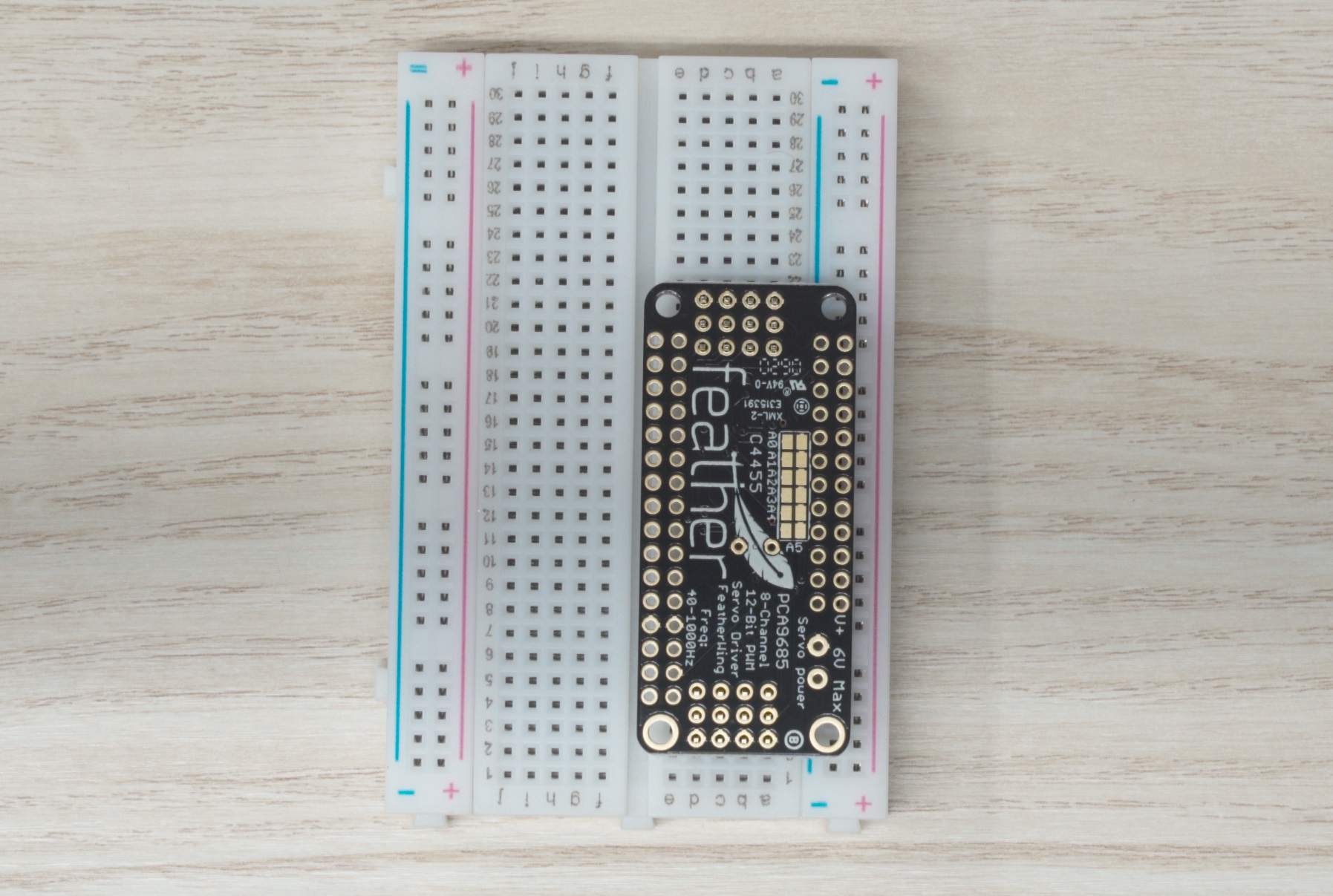
Servo Featherwing placed upside down on the 4x2 headers
Once the 4x3 headers are soldered in place, remove the featherwing from the breadboard and solder the 16x1 headers, while remembering to trim the short side to 11 pins.
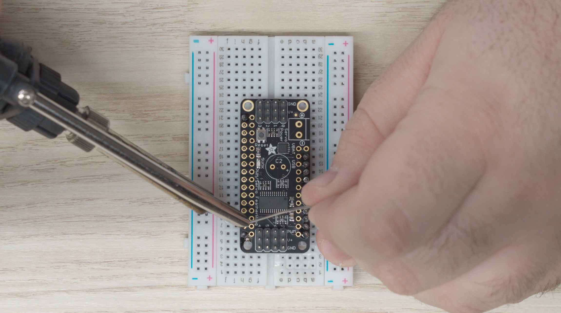
Servo Featherwing being soldered
Finally, we need to install the screw terminal:
- Remove the Featherwing from the breadboard.
- Place the screw terminal in the top of the circuit board with the terminals facing outward
- Turn the assembly upside down and place it on top of the breadboard.
- Solder the screw terminal on.
Installing the USB Power Jumper
In order to run the PCC from a laptop for testing, we’ll have to make a USB power jumper to connect the USB power from your laptop to the servo power rails. In the future, once the PCC makes its way onto the drone, the servos will have a dedicated power supply.
First, we need to install a pin for the wire to connect to:
- Find a spare male pin from the headers we used in the above steps
- Place the pin into the area labeled “USB” on the servo featherwing (highlighted below)
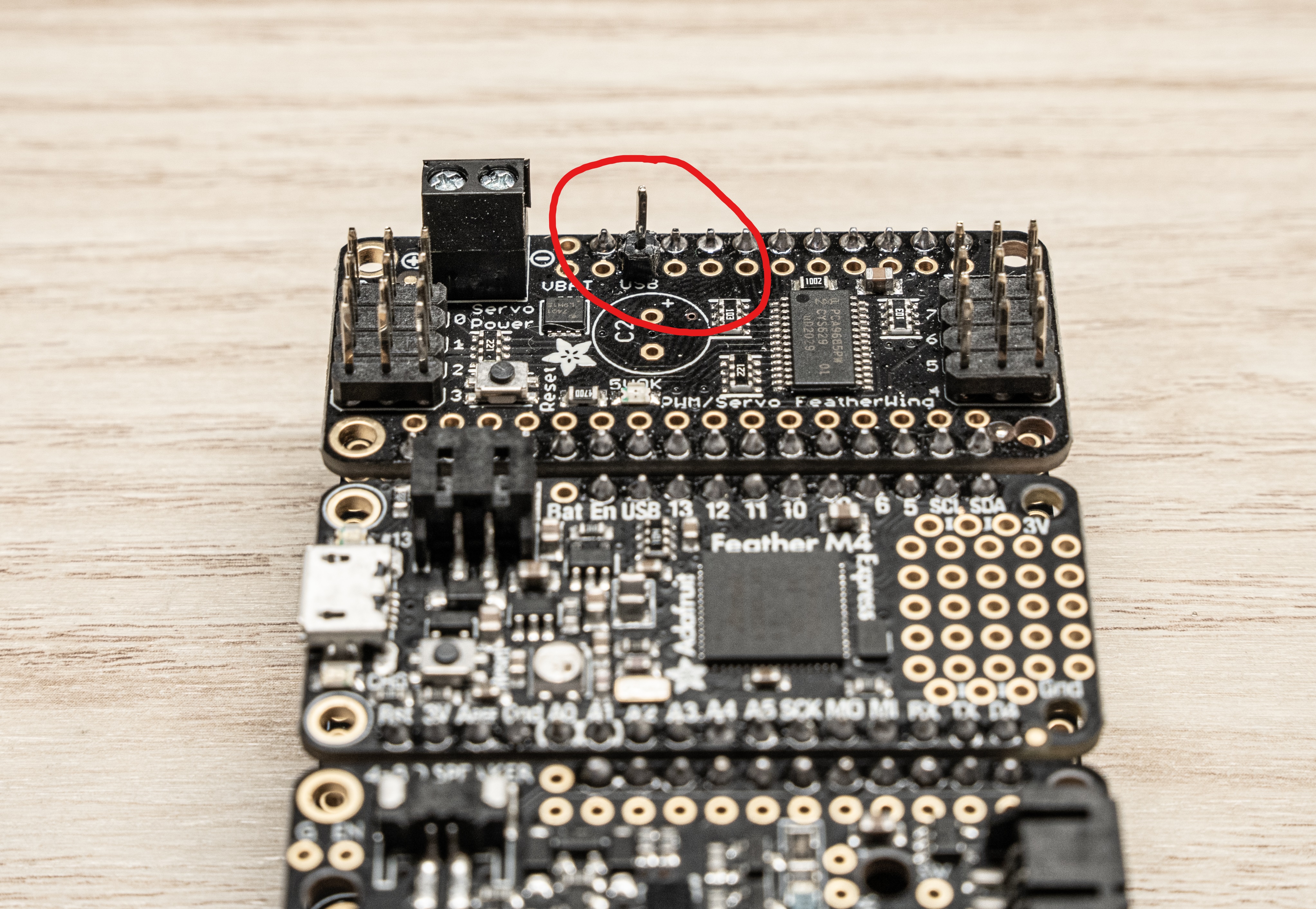
- Solder the pin from the underside
Now we need to make the jumper wire. Take a spare wire from the kit (there should be a whole bag with the proper connectors already on them) and cut it down to just about an inch. Then strip about 5mm from the end like shown below:
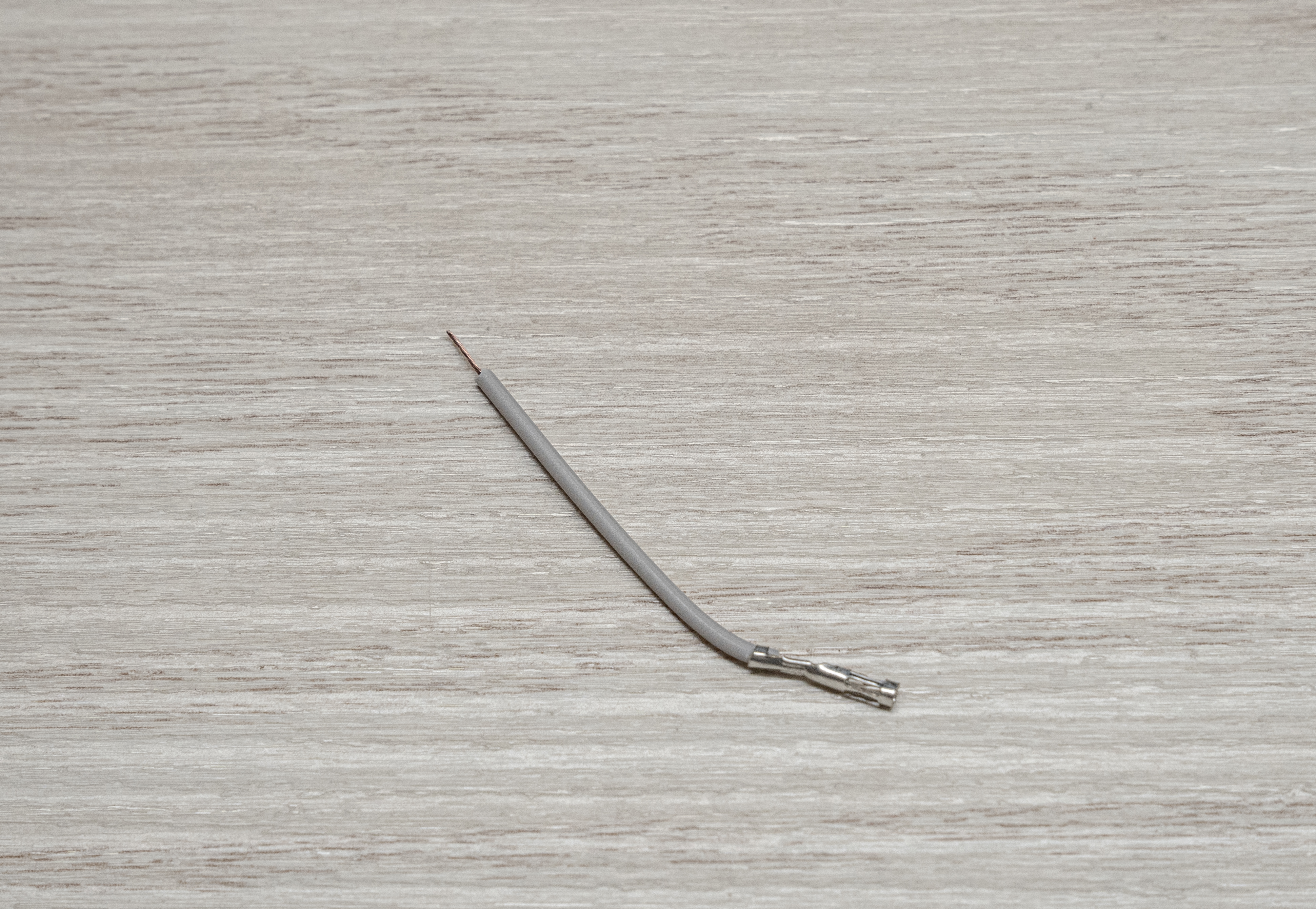
Finally, place the terminated end on the pin we just soldered, and the bare end into the + side of the terminal block and screw it down.
That’s it! The Servo Featherwing is now complete.
Solder the Featherwing Tripler
The tripler can be the trickiest piece to solder if you don’t follow this simple trick:
Hold the tripler circuit board with the silkscreen print facing upwards.
Drop the headers into the board as shown in the picture below:
Warning
It’s crucial that you place the headers in the orientation shown below! You should drop the headers into the board with the silkscreen facing up. Failure to catch this before soldering will mean that you’ll likely have to purchase another Tripler, as these parts are hard to desolder.
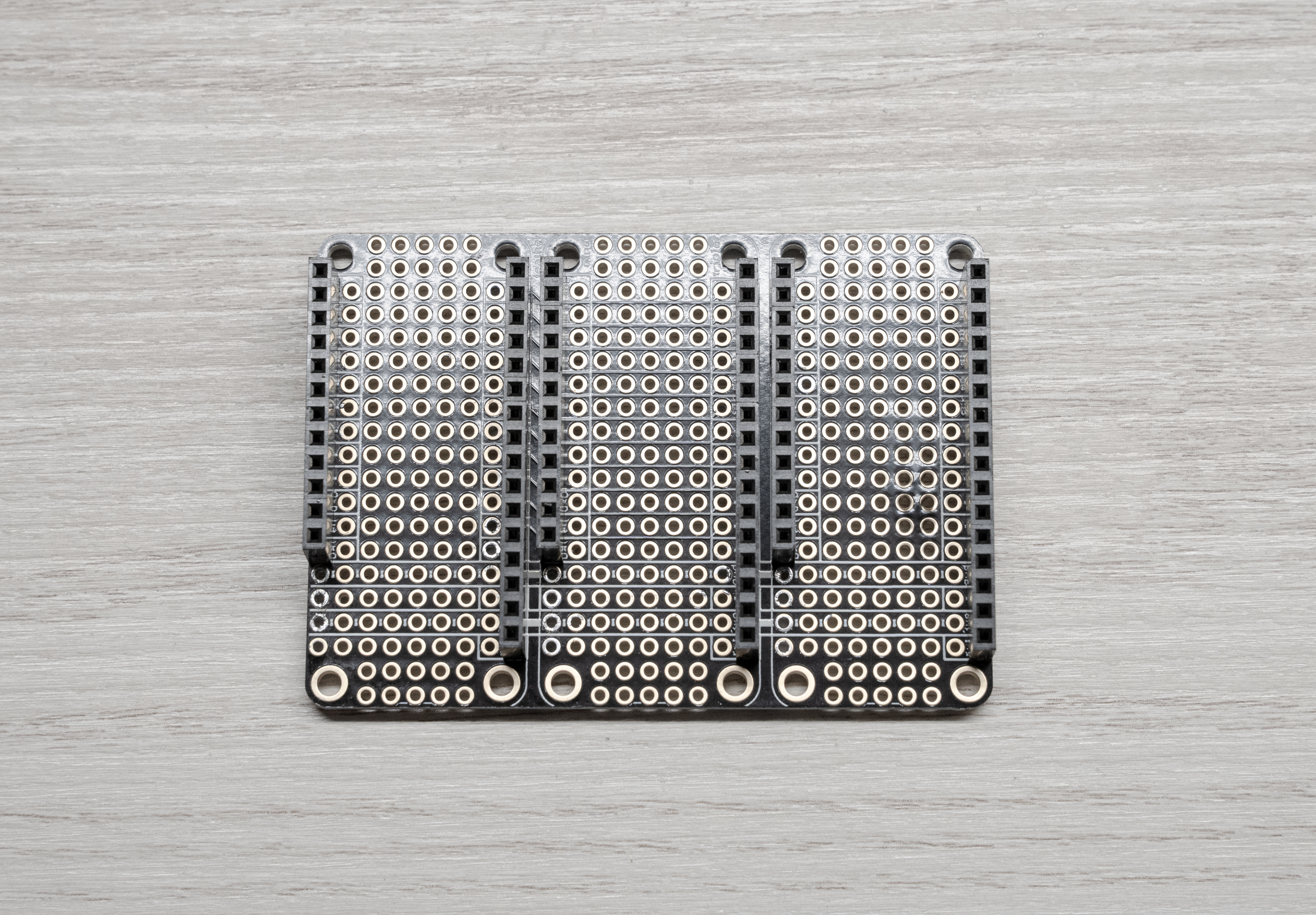
Then turn the whole thing over on its back (being careful not to drop the headers) and then solder each pin from here.
Tip
It’s easiest if you “tack” one pin from each row of headers and then tweak your alignment before doing the rest.
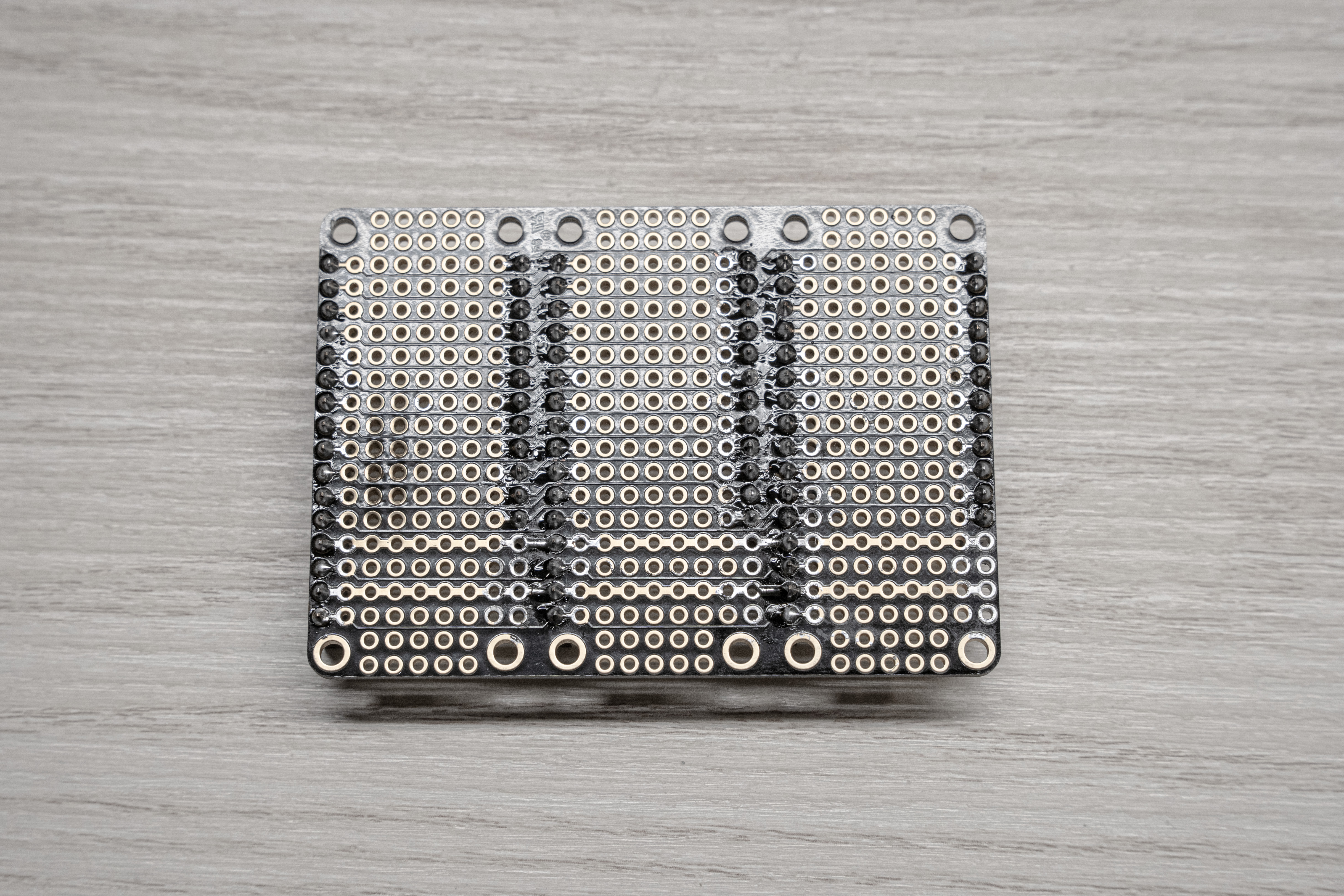
Back of soldered tripler for reference
Adding the Laser Trigger
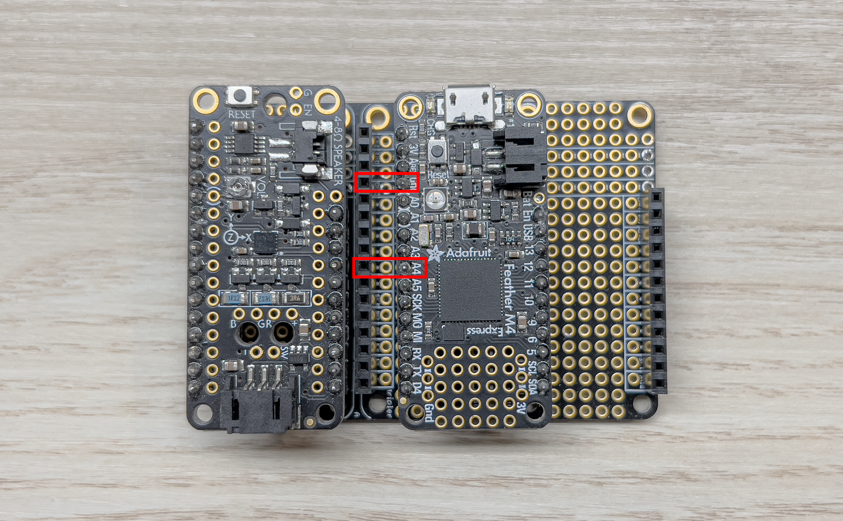
For the 2022 season, we are making use of a laser pointer. In order to be able to trigger the laser from the PCC we need to add some extra pins connected to GND and A4 on the express to the Tripler.
Start by placing the Tripler down, and lining up the M4 Express with the headers on the Tripler like shown below:
Tripler
I used a spare male dupont-connector wire to mark the pins of interest by plugging them into the desired spots on the header.
Next, grab some of the spare header pins and break two single-pins off:
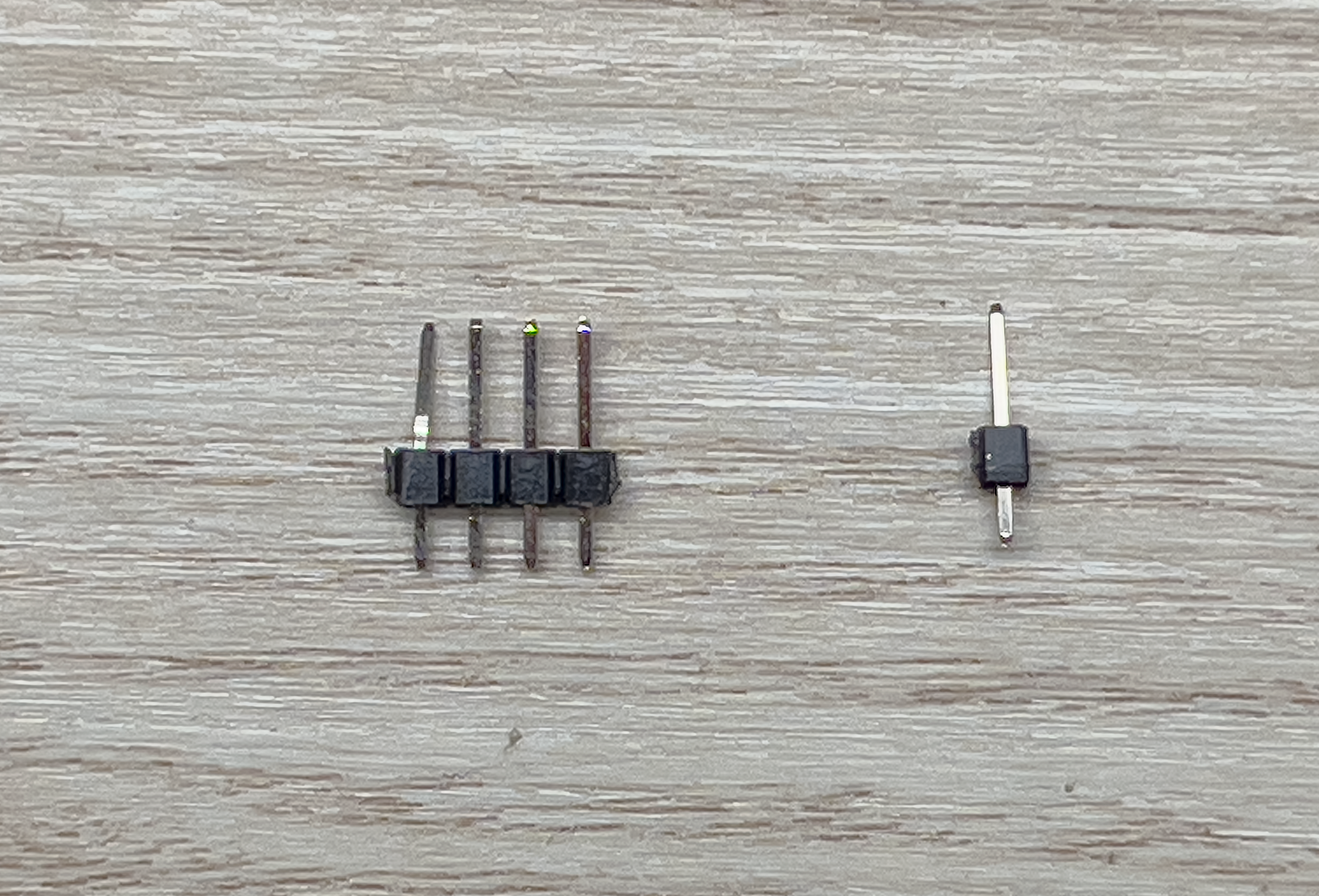
Separated Pin
Place them into the holes on the Tripler right next to the point of interest and use something flat to place over the board to hold the pins in place while you flip it over. I used an old PCB but you could use paper, cardboard, etc. Now solder the pins in place. You should now have something like this:
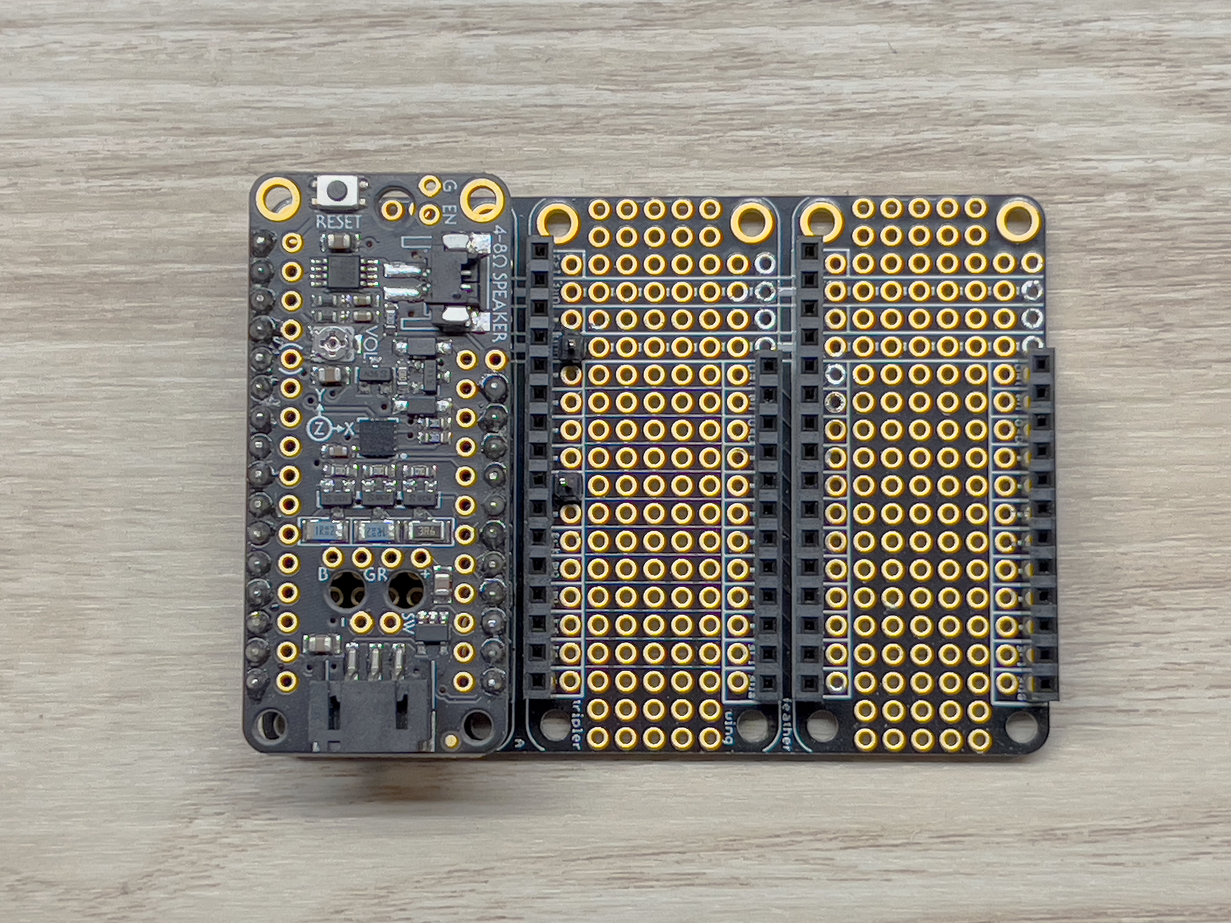
Soldered Pins
Now place a female dupont-connector wire on the pins and bend them down to the right. They should fit perfectly between the header rows like such:
Note
Be sure to use your 12 inch female-to-female jumper wires as these will eventually need to run from the top mounted PCC to the bottom mounted laser.
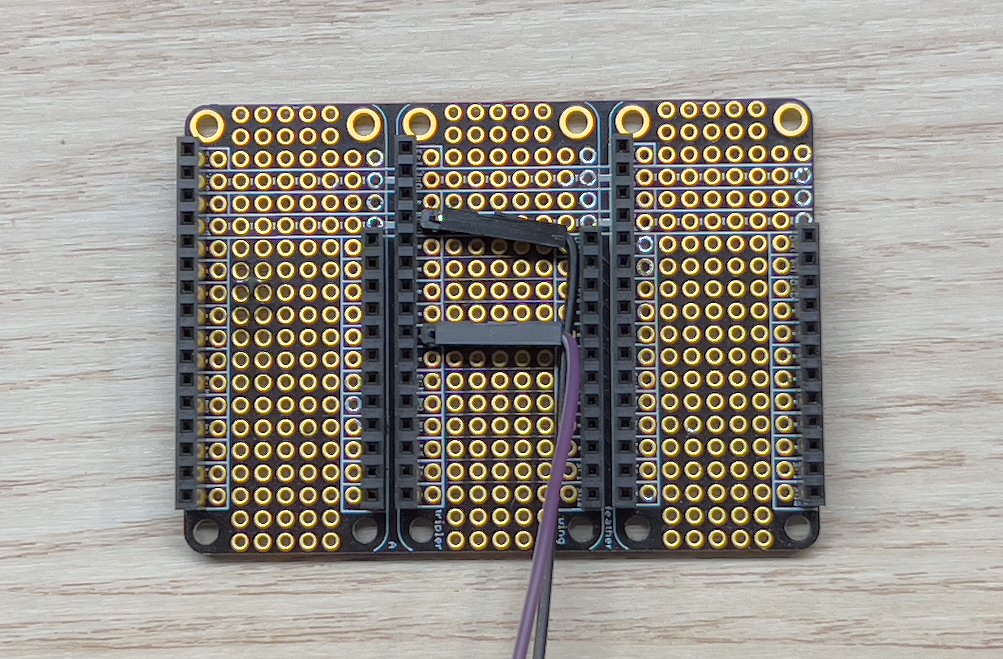
Bent Pins
Thats it! Move on to the next step!
Putting It All Together
Now we can just pop the Featherwings into the Tripler as shown below:
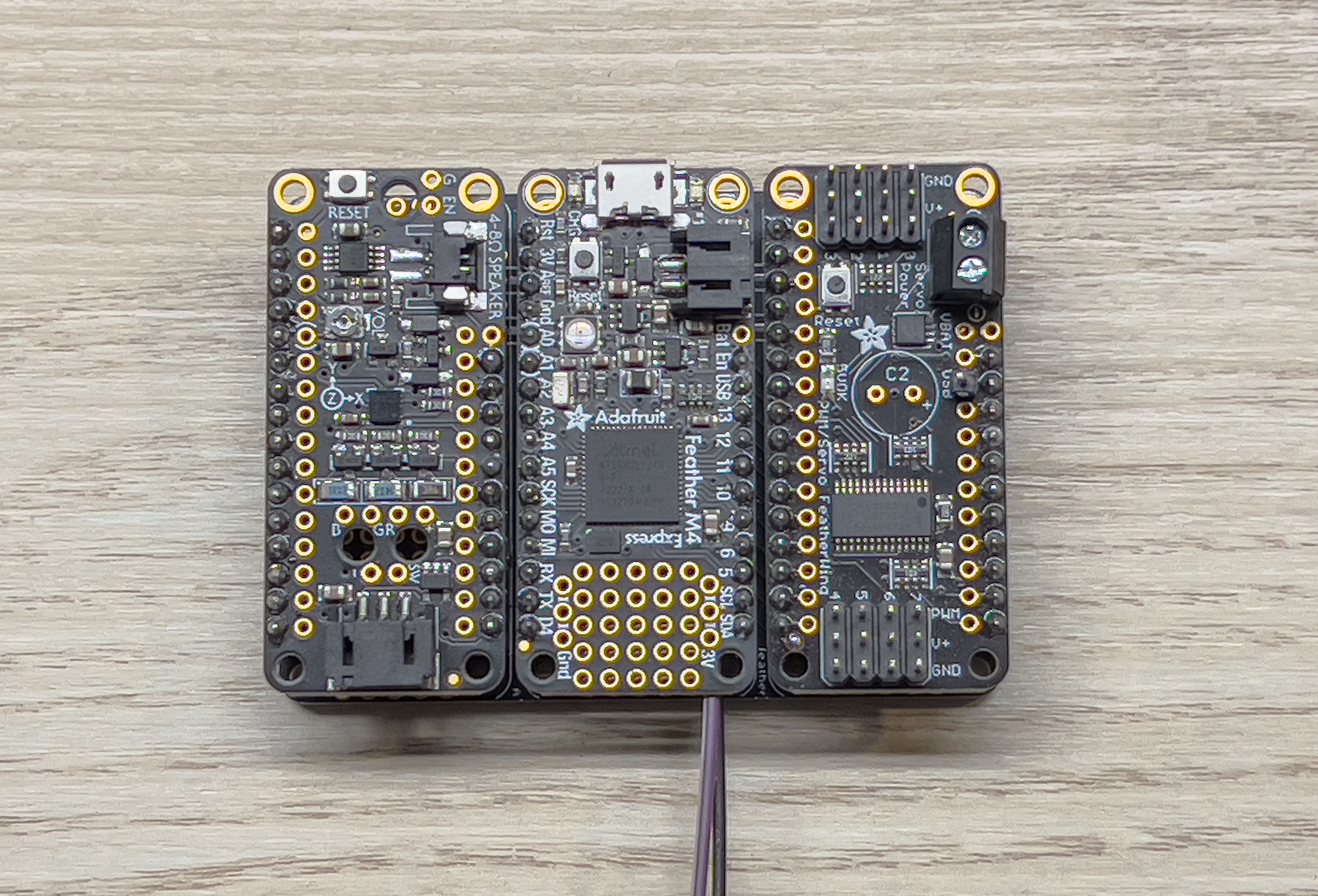
Completed PCC
Now your PCC is assembled!
←Previous Next→