This is the multi-page printable view of this section. Click here to print.
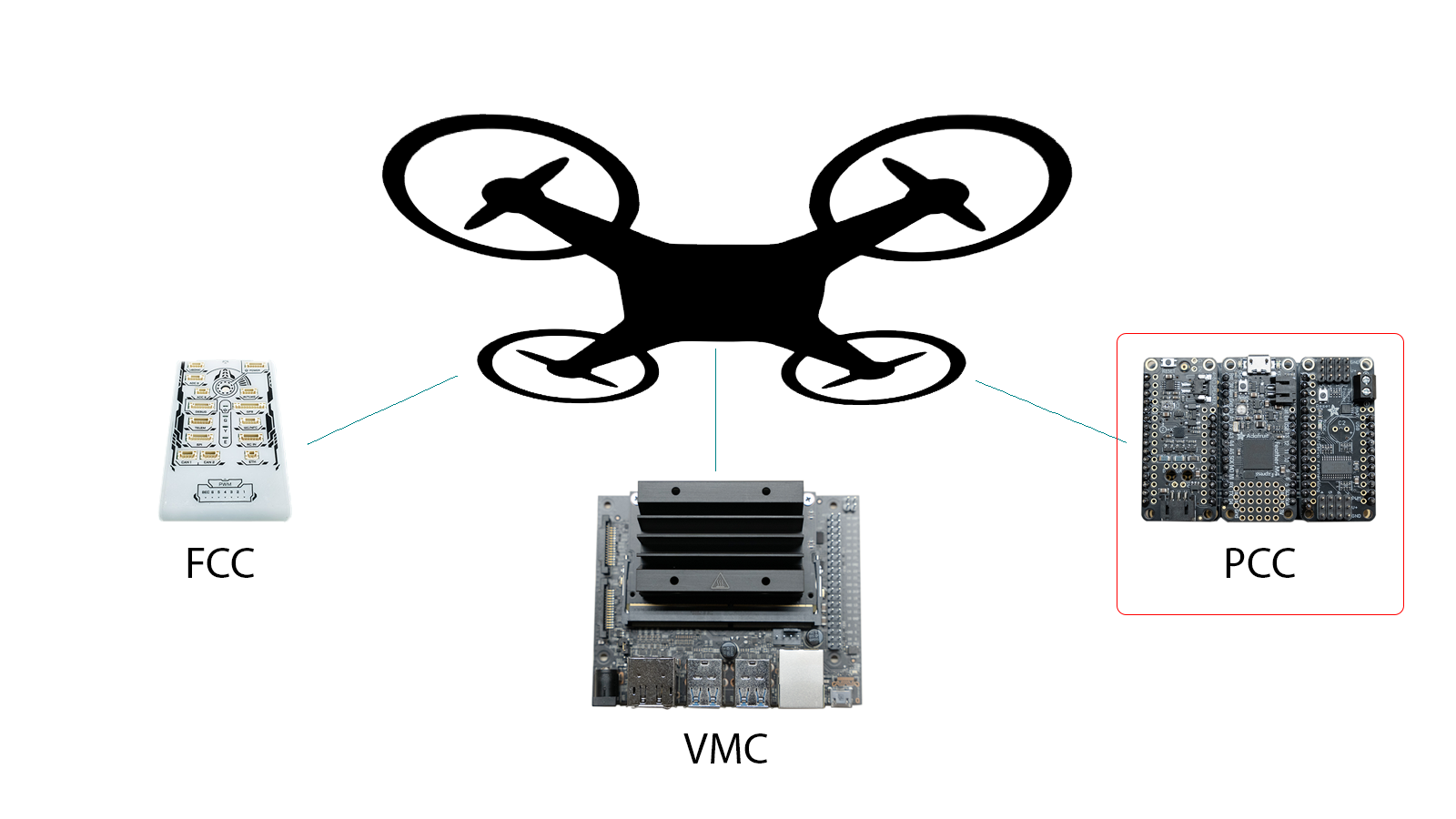
Peripheral Control Computer (PCC)
This guide covers the steps for assembling the Peripheral Control Computer, which will control LEDs and servos.
- 1: Physical Assembly
- 2: Flash the PCC
- 3: Test the PCC
1 - Physical Assembly
Assembling the Peripheral Control Computer is fairly easy, and just requires a bit of soldering.
Tools Needed
- Soldering Iron (I used an iron at 450C, but the recommended solder melts around 200C)
- Soldering Iron Tip Cleaner
- Solder (Recommend 60/40 Tin/Lead)
- Wire Strippers
- Breadboard
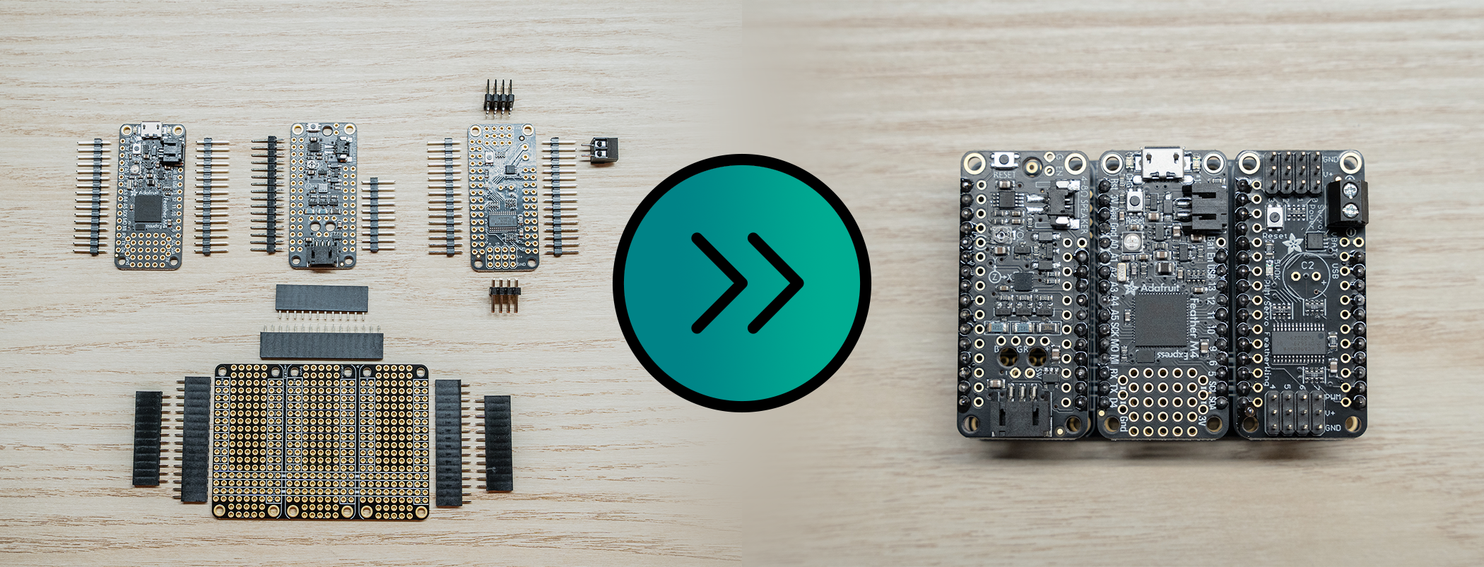
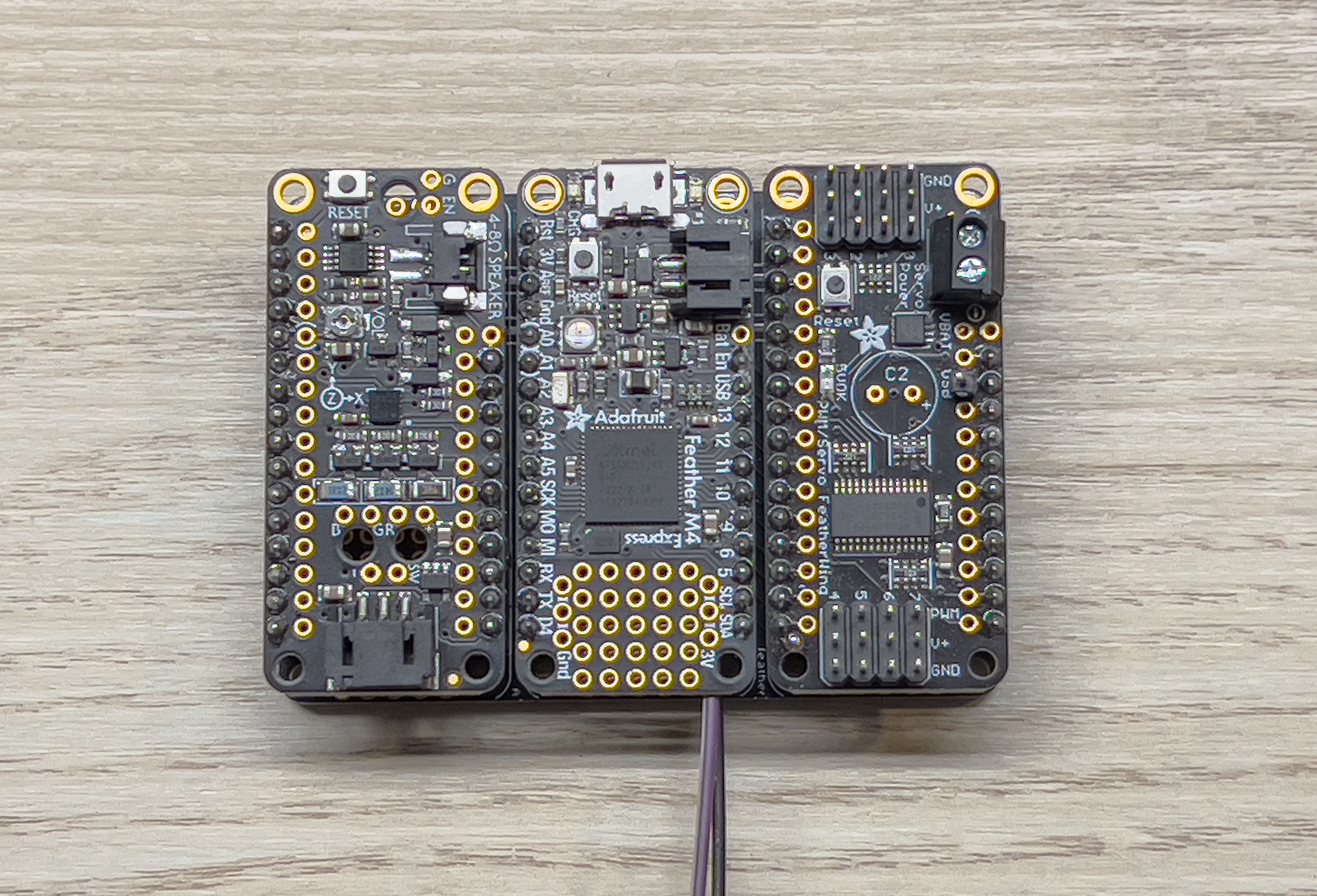
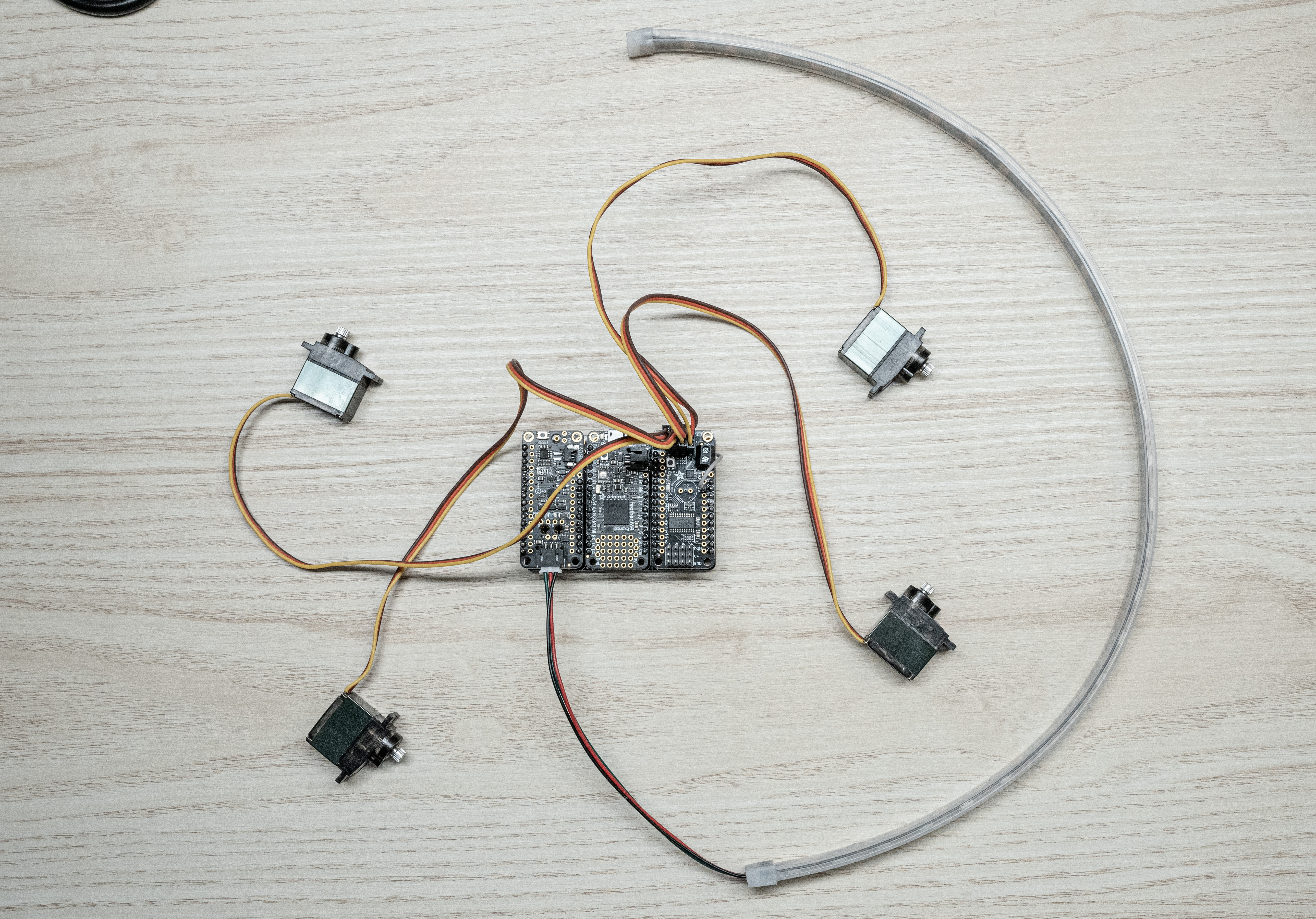
PCC Parts - Box 5
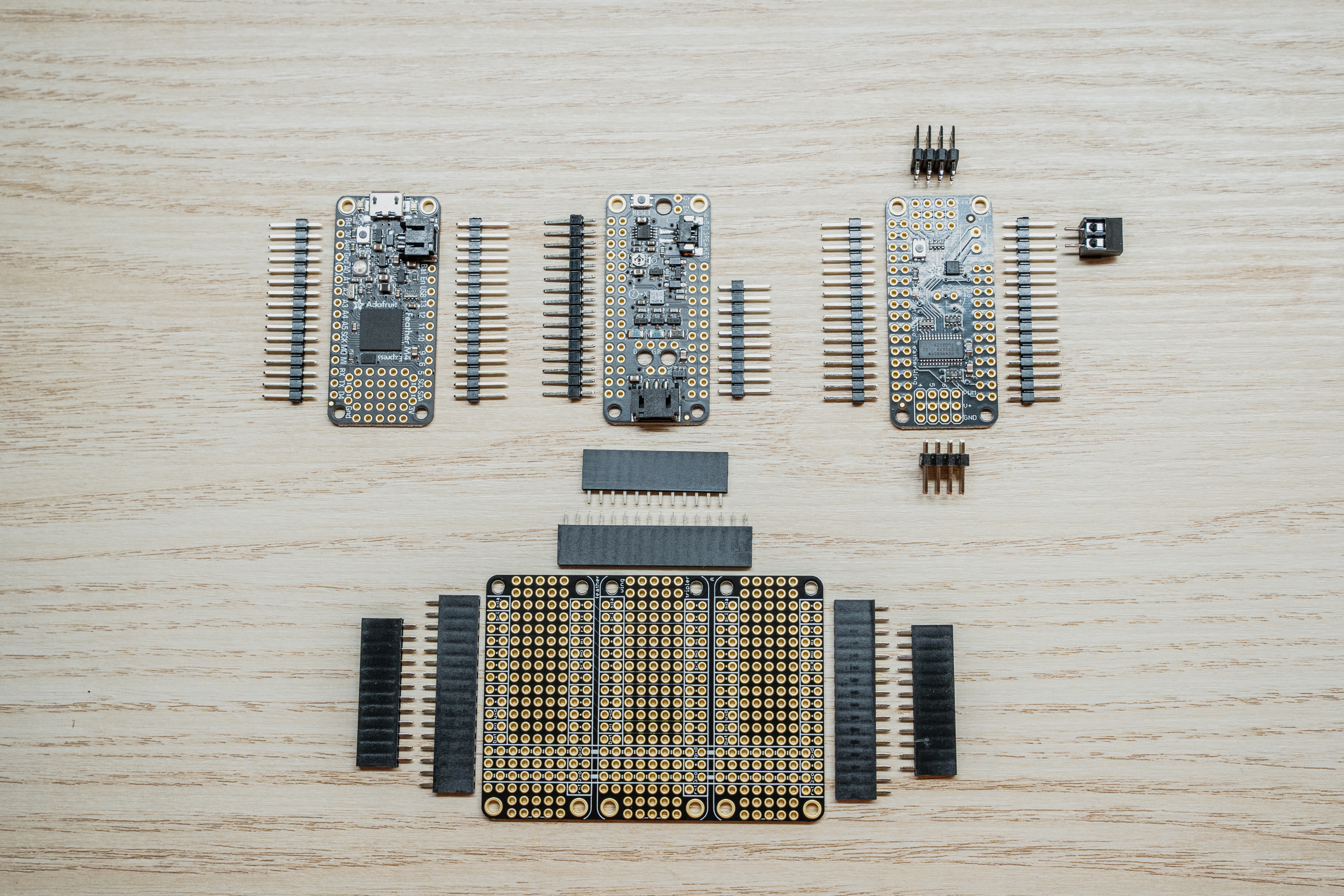
Before we get started, let’s make sure we have all the necessary parts for the PCC.
The PCC ships in 4 plastic bags consisting of the following:
- 1 x Adafruit Feather M4 Express (Pictured upper left)
- 2 x 16x1 Male Pin Headers
- 1 x Adafruit Prop Maker Featherwing (Pictured upper middle)
- 2 x 16x1 Male Pin Headers
- 1 x Adafruit Servo/PWM Featherwing (Pictured upper right)
- 2 x 16x1 Male Pin Headers
- 2 x 4x3 Male Pin Headers
- 1 x 2 screw-terminal thru-hole adapter
- 1 x Adafruit Featherwing Tripler (Pictured Bottom)
- 3 x 12x1 Female Pin Headers
- 3 x 16x1 Female Pin Headers
Note
The picture only has a 9 pin header for the Prop Maker, because mine broke off in shipping. Don’t worry this isn’t an issue, just place them together when it’s time to solder.Solder the Feather M4 Express
Before we dive in, let’s go over a couple of warnings and tips.
Warning
Soldering irons get hot… like really really hot. Pay attention to finger placement, and don’t burn yourself.Tip
The key to an enjoyable soldering experience is patience, a clean tip, and a hot iron.Step 1: Assemble Feather M4 Express
The Feather M4 is the brains of the PCC. It receives commands from the VMC and executes them in order to change the color of the LEDs or move a servo.
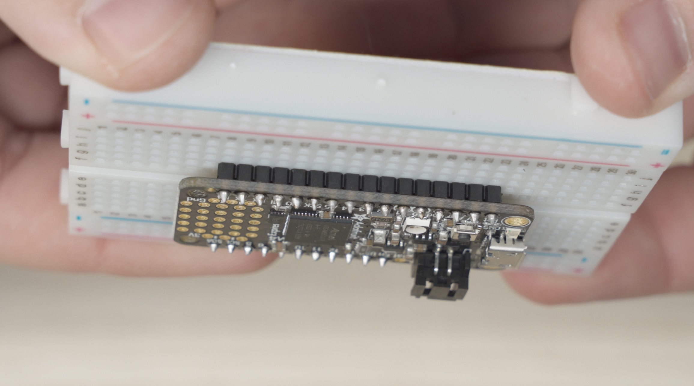
You’ll see that the M4 Express has 16 pins along its left side (assuming the micro USB port is the top), and 12 pins along the right side. Because the M4 Express ships with 2 x 16x1 headers, we need to cut one side down. You should be able to use scissors to trim one of the headers to 11 pins. Why 11? The PCC doesn’t make use of the “Bat” pin and in our testing including this pin caused issues. For this reason, we chose to omit this pin. You can see it is missing if you expand the picture below:
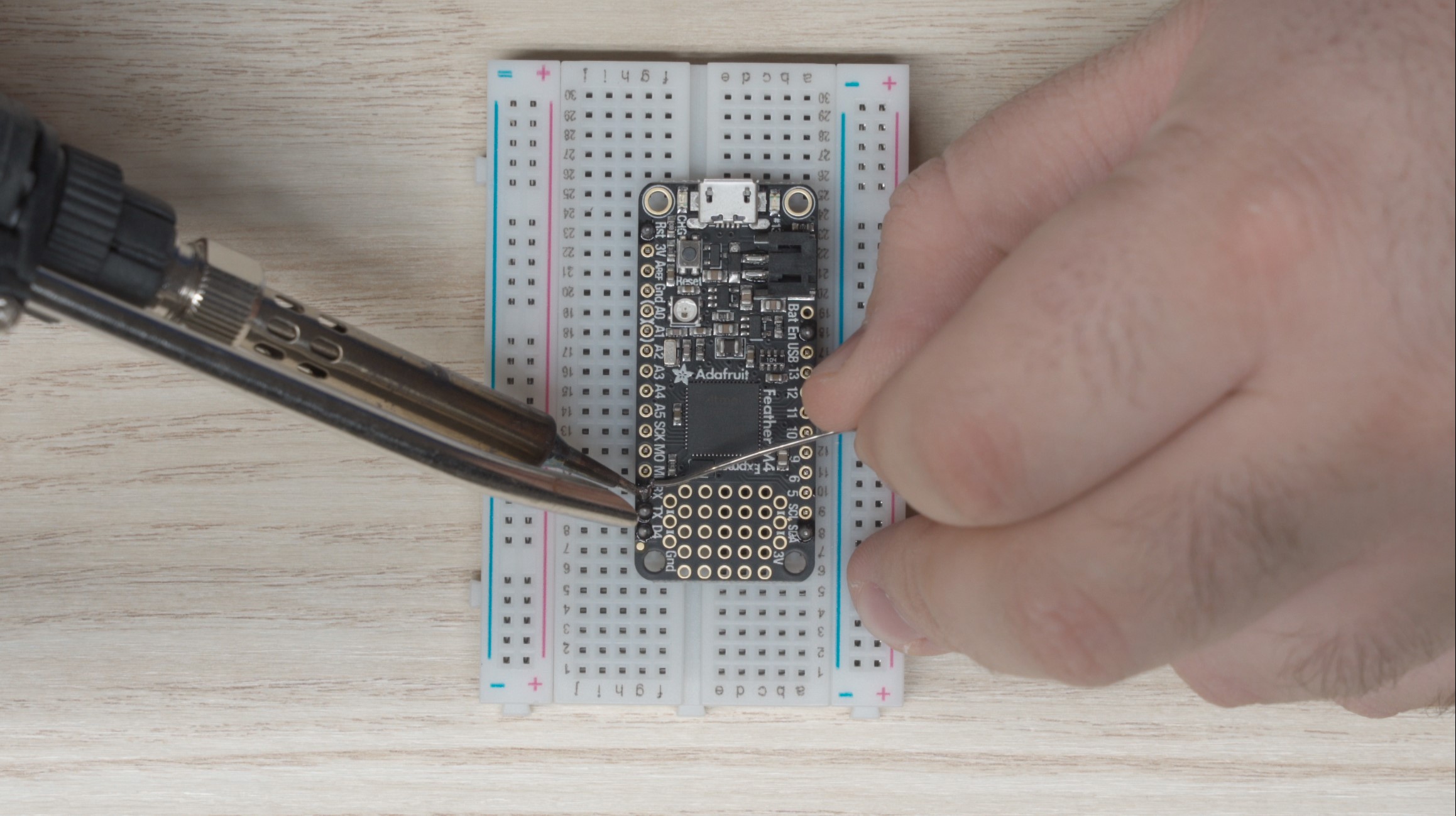
M4 Express being soldered
Tip
Place the headers in the breadboard, long side down to act as a fixture for soldering. It will be much easier this way.With the headers cut to length, grab your breadboard and place the headers in the “a” and “g” column as in the picture above, with the long side of the headers going into the breadboard. Make sure it’s lined up correctly and set the M4 Express onto the pins. The feather should not move around anymore and you can begin soldering.
For the smoothest outcome, start by soldering the pins in the four corners so the pins don’t move around on you when soldering the rest. I like to use a hot iron (around 450°C) with a fine tip for this.
Use the following steps to complete a solder joint:
- Place the iron tip on the feather such that it is making contact with the protruding pin as well as the donut-shaped pad that the pin protrudes through.
- If your iron is clean and hot, after about 5 seconds you should be able to move your solder in to touch the iron at the junction where the iron and the pin meet. The solder should melt almost immediately, and wick around the pin.
- Don’t go overboard with the solder. You want just enough that the solder forms a cone shape around the pin. Less really is more here.
- Pull the solder and iron away from the board and inspect your work.
- Repeat steps 1 through 4 for each pin on the M4 Express.
Once complete you should have solder joints that look like this:
Completed M4 Express
Once you’re happy with your soldering work, grab each end (the micro-usb and opposite side) and slowly inch the feather out of the breadboard. It is very easy to bend a pin trying to remove it so just go slow and be careful.
Tip
If you bend a pin removing the soldered part from the breadboard, use some needle nose pliers to bend it back straight. Don’t work the pin too much though, or you’ll break it.Hopefully that wasn’t too bad! Now we need to repeat similar steps for the prop maker and the servo featherwing.
Solder the Prop Maker
The steps for the Prop Maker are the same as the M4 Express.
Make sure to cut one set of male headers down to 11 pins and skip the “Bat” pinhole.
Place the headers into the breadboard and solder all the pins.
Prop Maker being soldered
Solder the Servo/PWM Featherwing
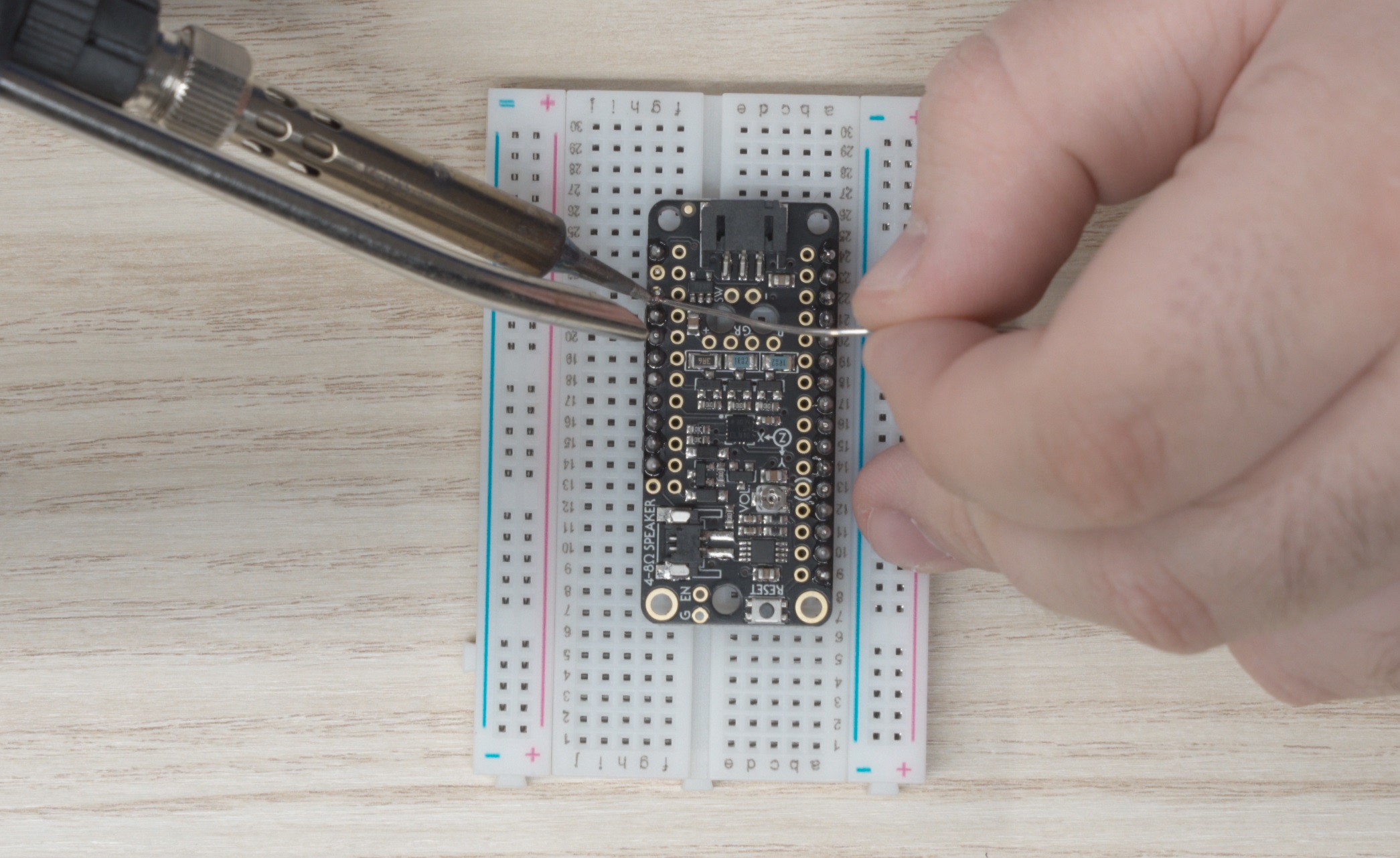
For the Servo featherwing its easiest if you solder the 4x3 headers first:
- Place one of the headers into the breadboard first.
- Place the other set short-end first into the top of the featherwing.
- Flip the featherwing upside down and onto the headers already inserted in the breadboard.
- Solder these pins
Servo Featherwing placed upside down on the 4x2 headers
Once the 4x3 headers are soldered in place, remove the featherwing from the breadboard and solder the 16x1 headers, while remembering to trim the short side to 11 pins.
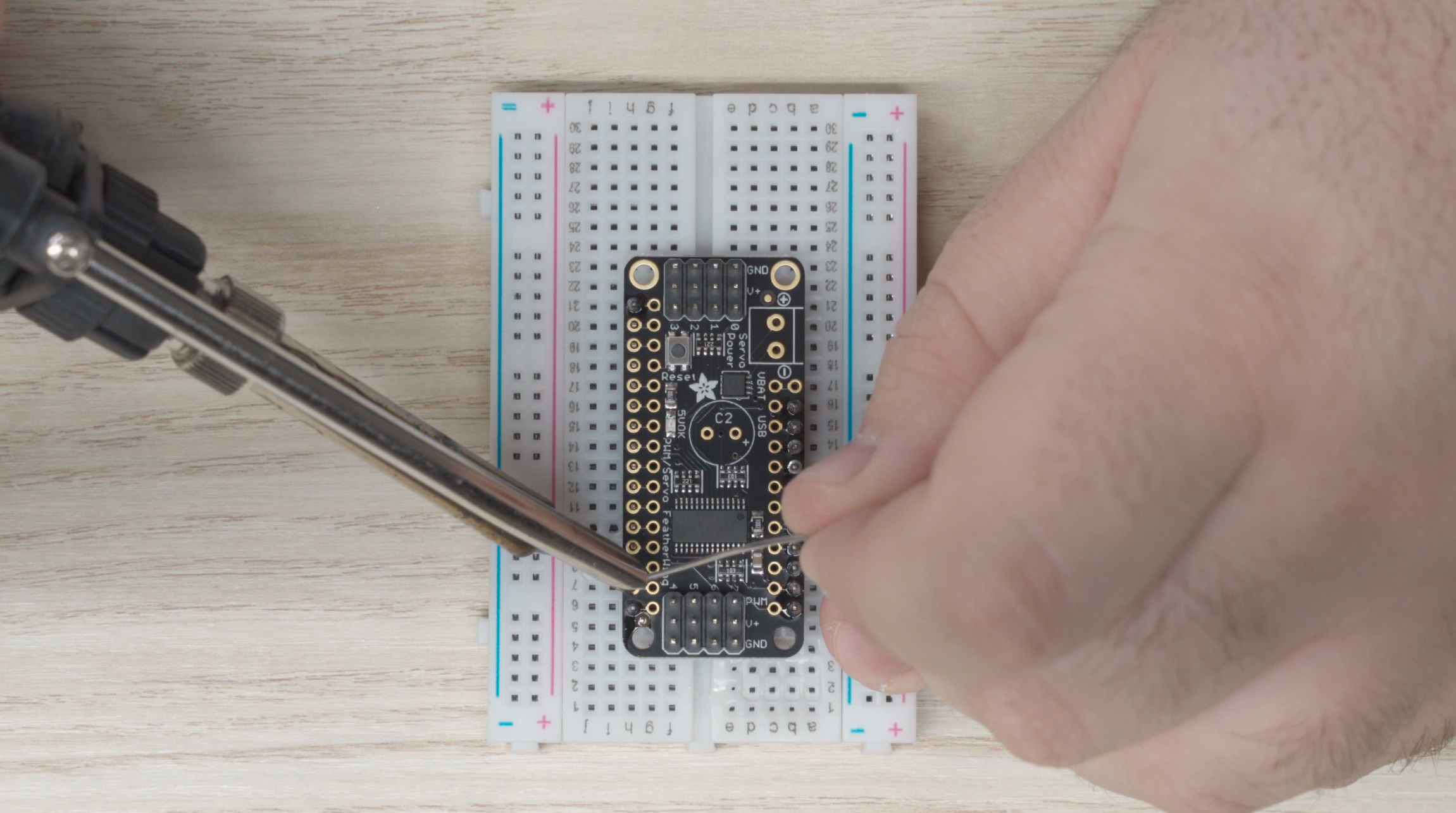
Servo Featherwing being soldered
Finally, we need to install the screw terminal:
- Remove the Featherwing from the breadboard.
- Place the screw terminal in the top of the circuit board with the terminals facing outward
- Turn the assembly upside down and place it on top of the breadboard.
- Solder the screw terminal on.
Installing the USB Power Jumper
In order to run the PCC from a laptop for testing, we’ll have to make a USB power jumper to connect the USB power from your laptop to the servo power rails. In the future, once the PCC makes its way onto the drone, the servos will have a dedicated power supply.
First, we need to install a pin for the wire to connect to:
- Find a spare male pin from the headers we used in the above steps
- Place the pin into the area labeled “USB” on the servo featherwing (highlighted below)
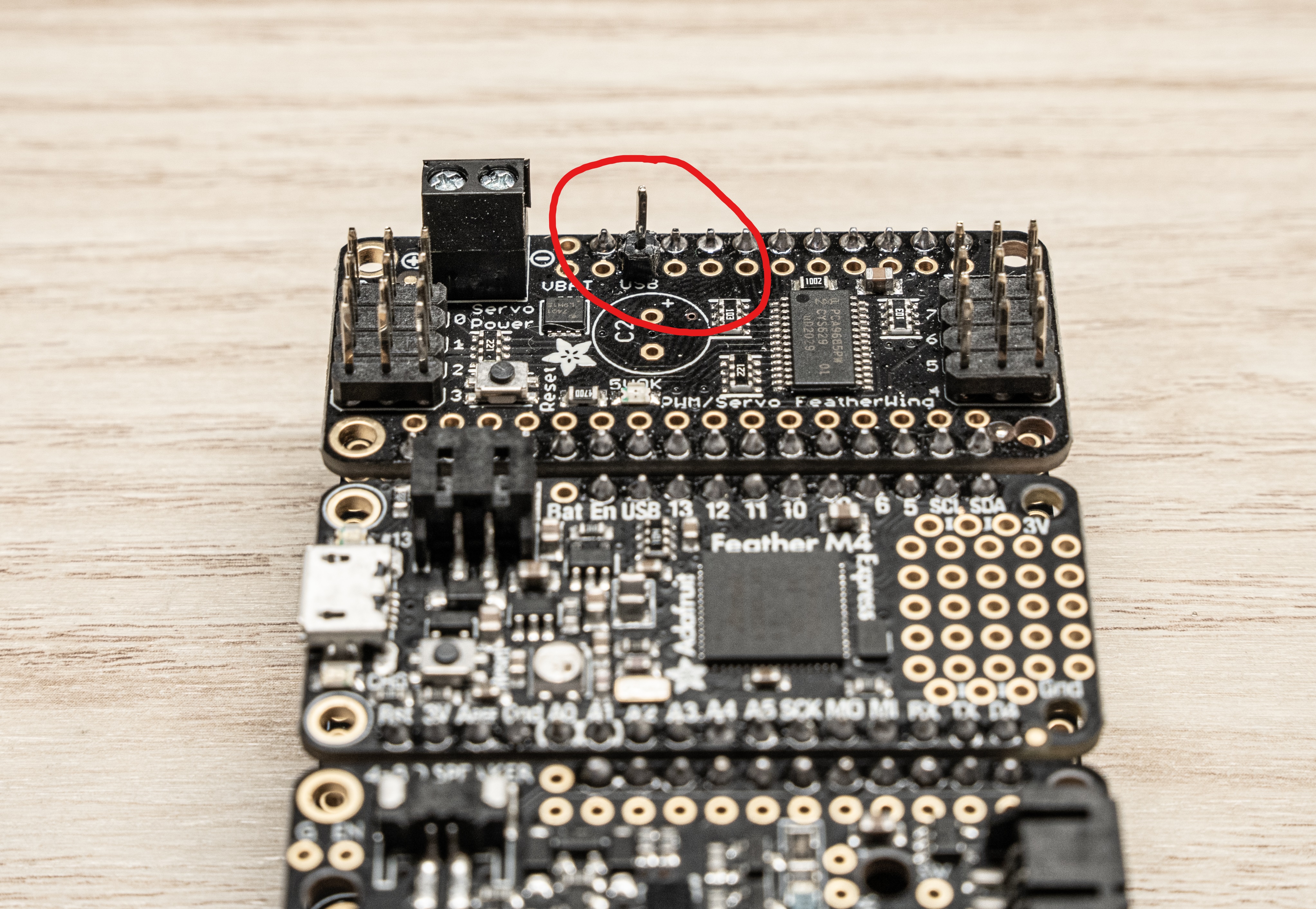
- Solder the pin from the underside
Now we need to make the jumper wire. Take a spare wire from the kit (there should be a whole bag with the proper connectors already on them) and cut it down to just about an inch. Then strip about 5mm from the end like shown below:
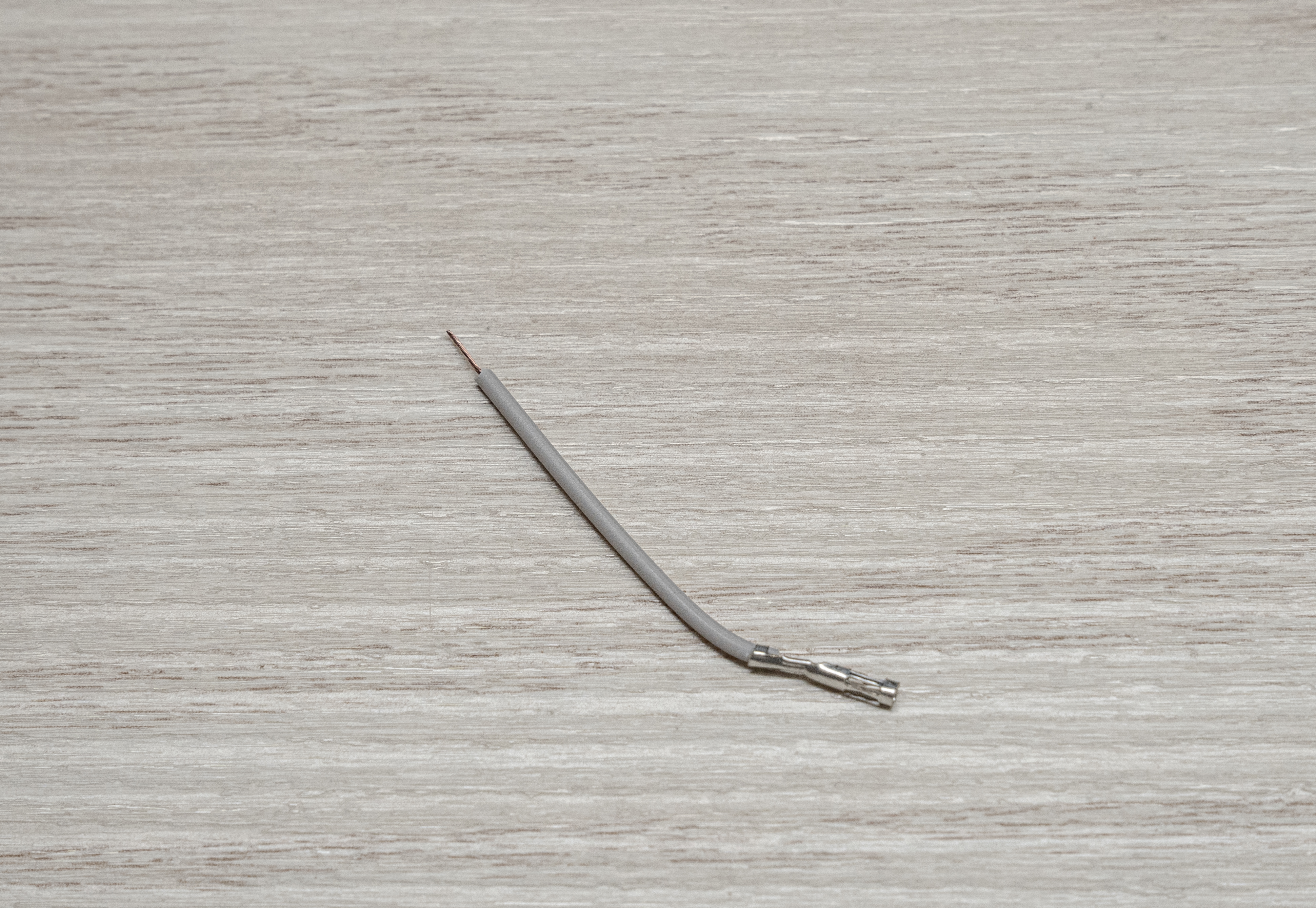
Finally, place the terminated end on the pin we just soldered, and the bare end into the + side of the terminal block and screw it down.
That’s it! The Servo Featherwing is now complete.
Solder the Featherwing Tripler
The tripler can be the trickiest piece to solder if you don’t follow this simple trick:
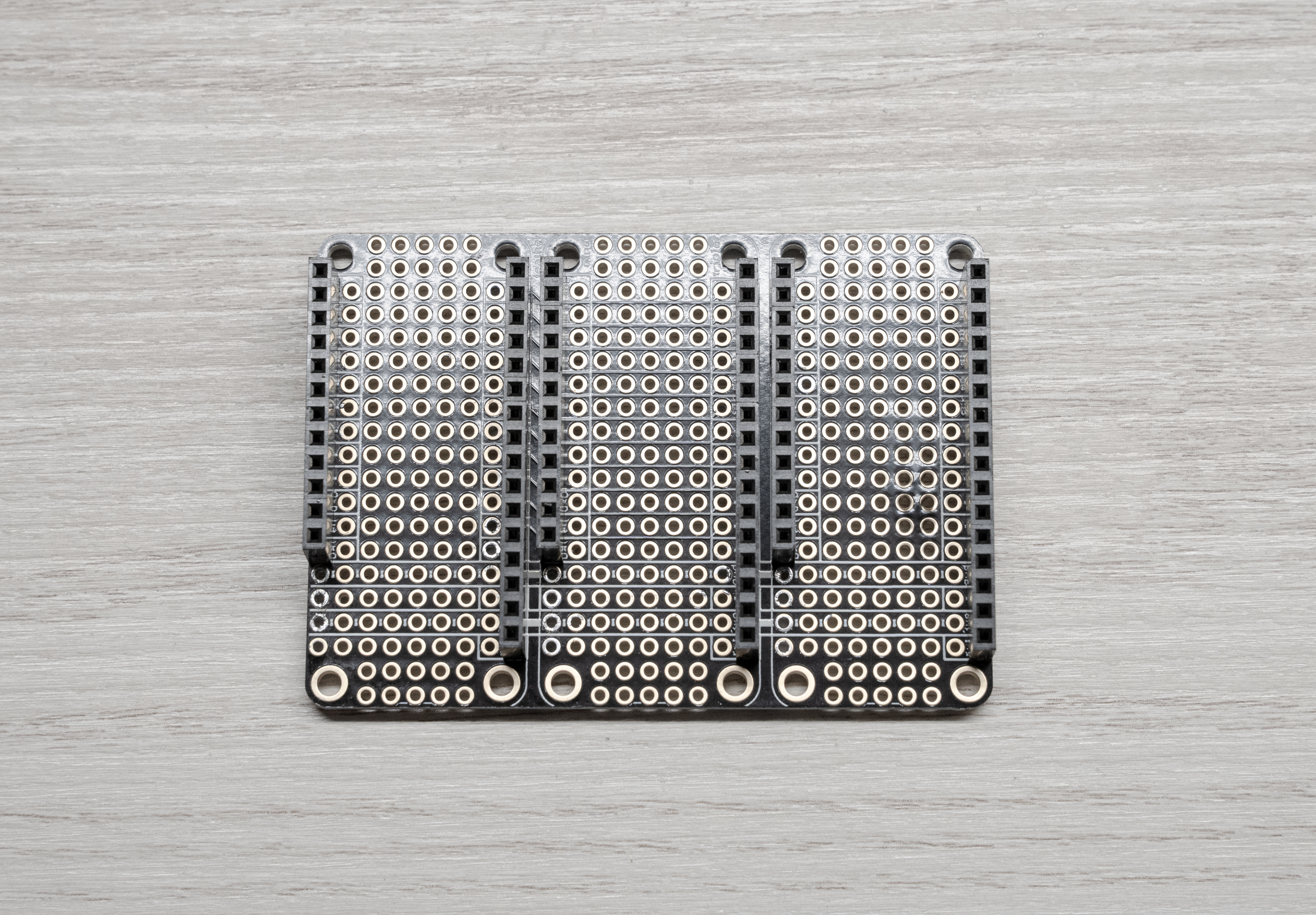
Hold the tripler circuit board with the silkscreen print facing upwards.
Drop the headers into the board as shown in the picture below:
Warning
It’s crucial that you place the headers in the orientation shown below! You should drop the headers into the board with the silkscreen facing up. Failure to catch this before soldering will mean that you’ll likely have to purchase another Tripler, as these parts are hard to desolder.
Then turn the whole thing over on its back (being careful not to drop the headers) and then solder each pin from here.
Tip
It’s easiest if you “tack” one pin from each row of headers and then tweak your alignment before doing the rest.
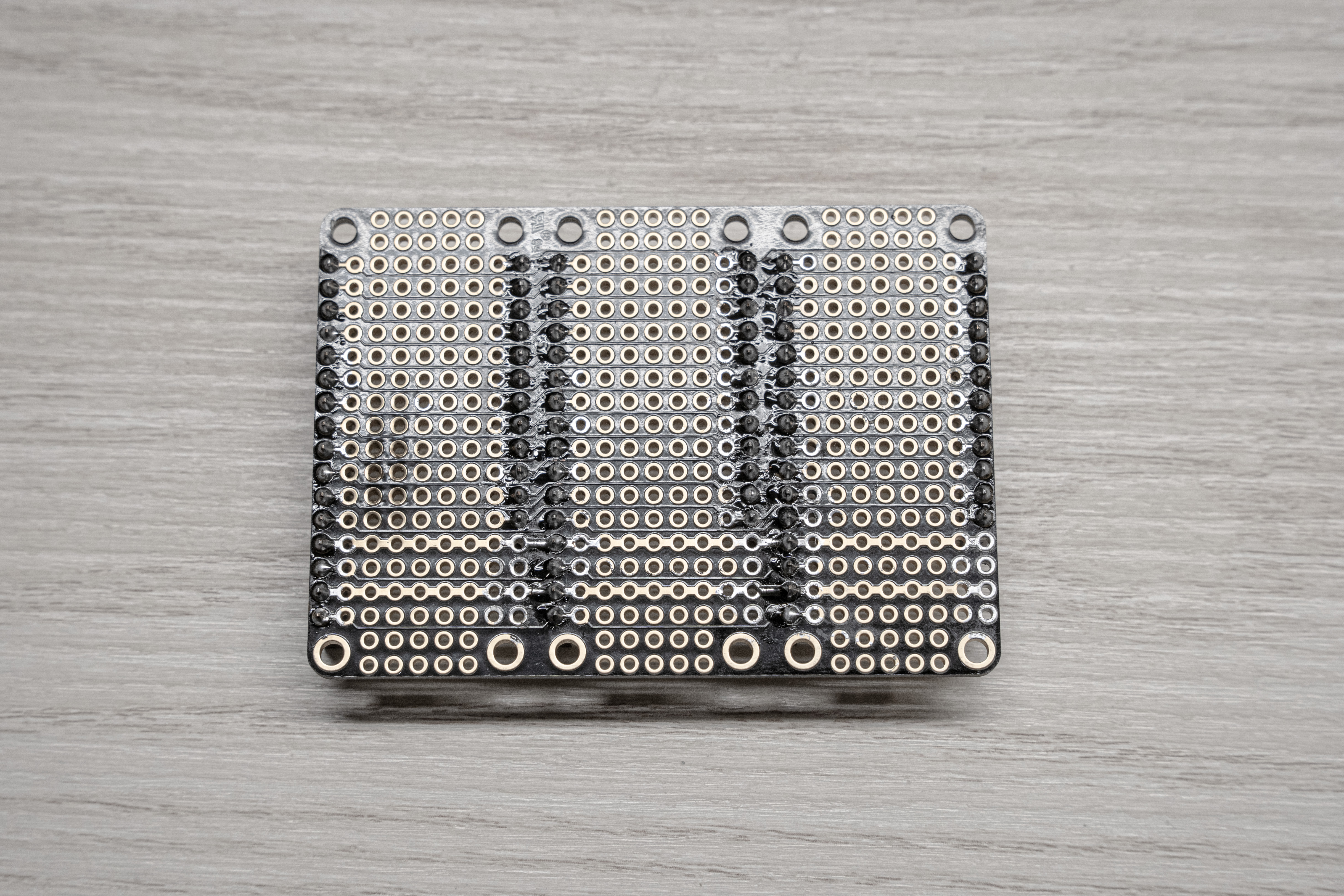
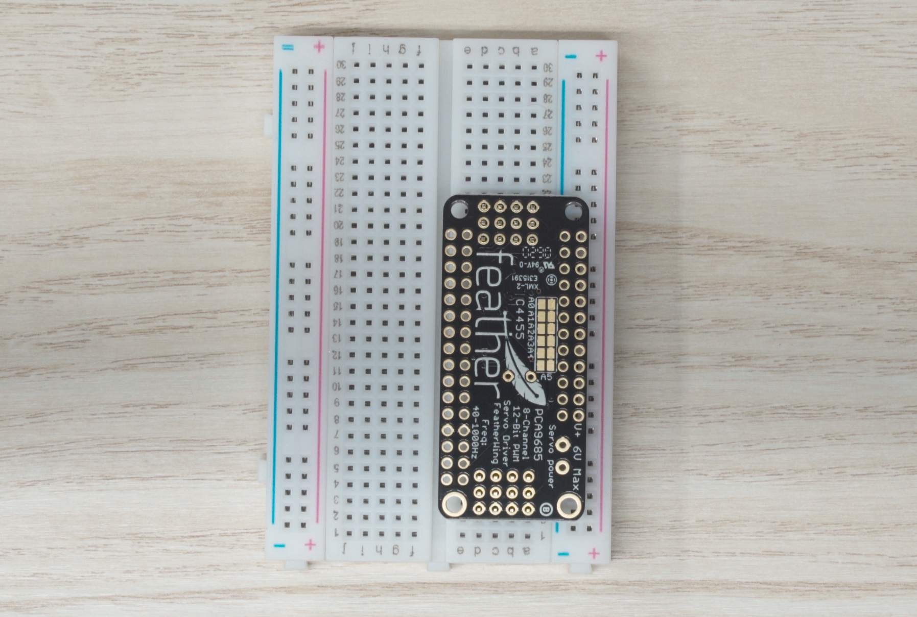
Back of soldered tripler for reference
Adding the Laser Trigger
For the 2022 season, we are making use of a laser pointer. In order to be able to trigger the laser from the PCC we need to add some extra pins connected to GND and A4 on the express to the Tripler.
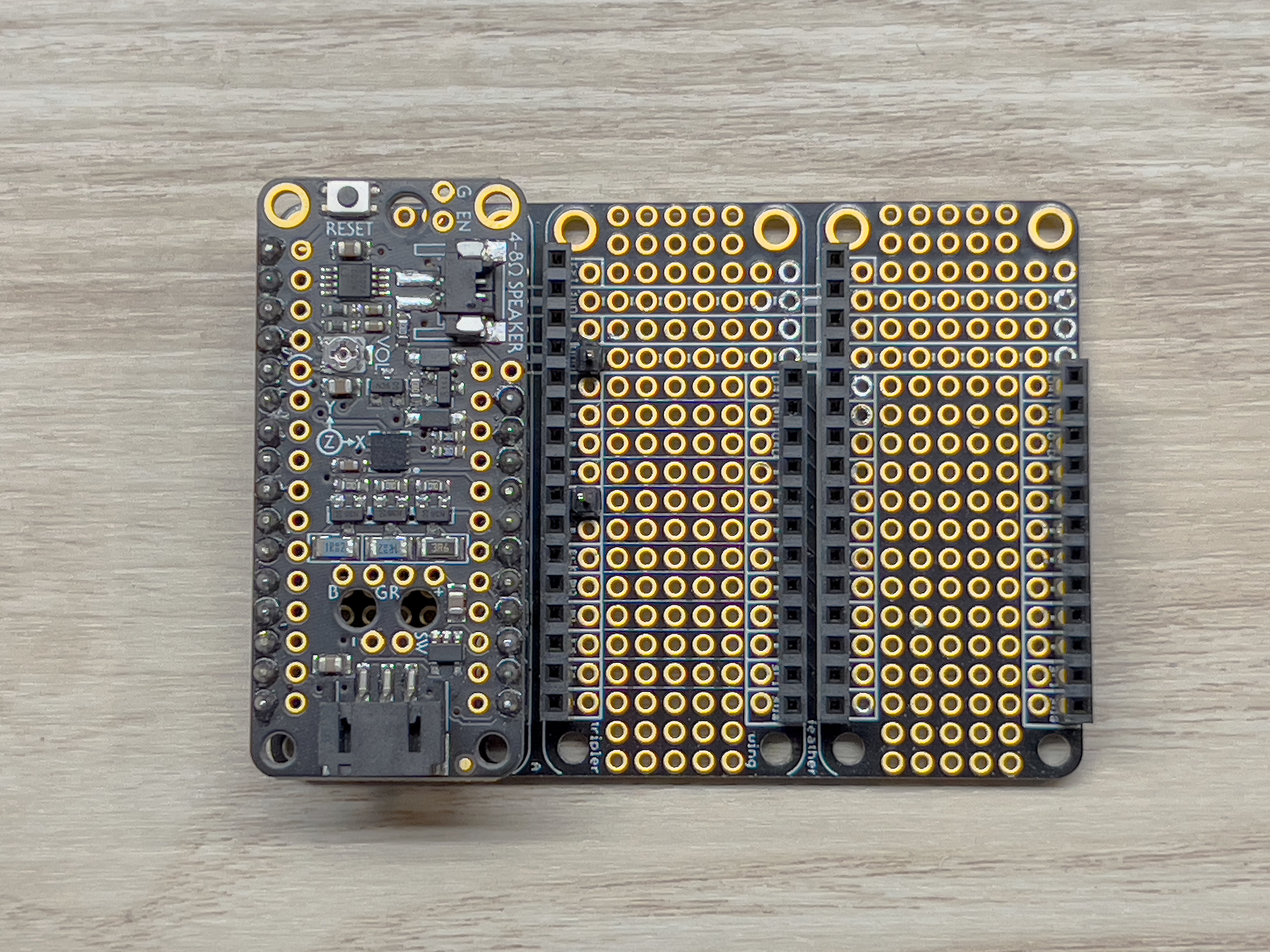
Start by placing the Tripler down, and lining up the M4 Express with the headers on the Tripler like shown below:
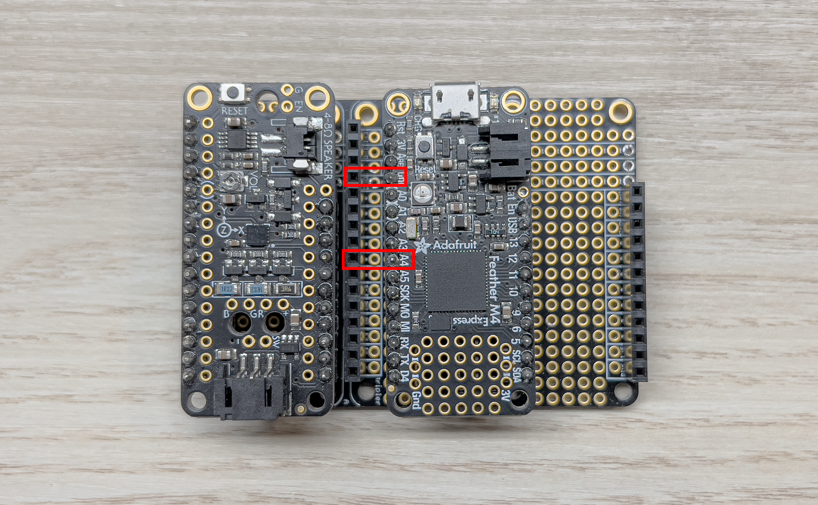
Tripler
I used a spare male dupont-connector wire to mark the pins of interest by plugging them into the desired spots on the header.
Next, grab some of the spare header pins and break two single-pins off:
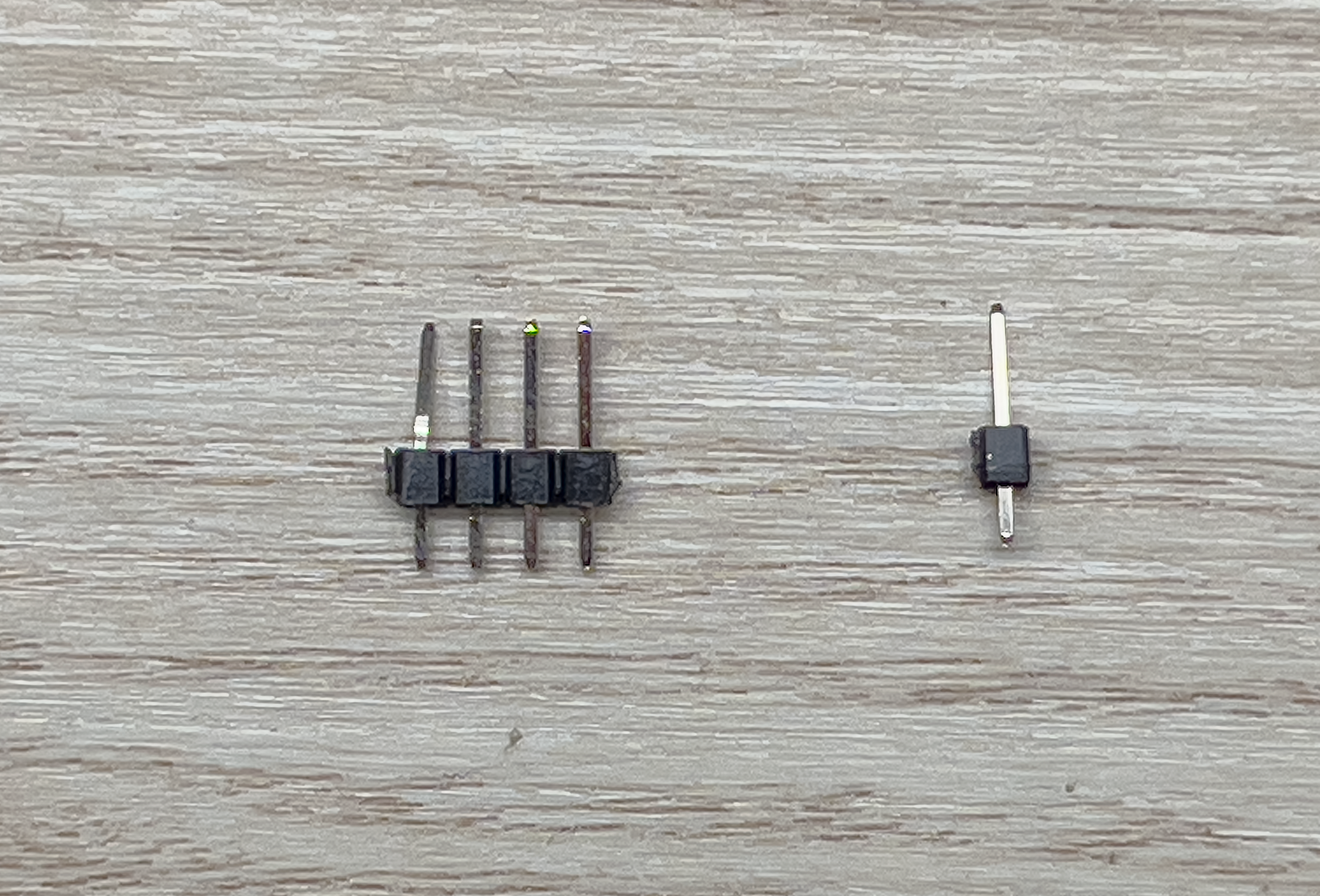
Separated Pin
Place them into the holes on the Tripler right next to the point of interest and use something flat to place over the board to hold the pins in place while you flip it over. I used an old PCB but you could use paper, cardboard, etc. Now solder the pins in place. You should now have something like this:
Soldered Pins
Now place a female dupont-connector wire on the pins and bend them down to the right. They should fit perfectly between the header rows like such:
Note
Be sure to use your 12 inch female-to-female jumper wires as these will eventually need to run from the top mounted PCC to the bottom mounted laser.
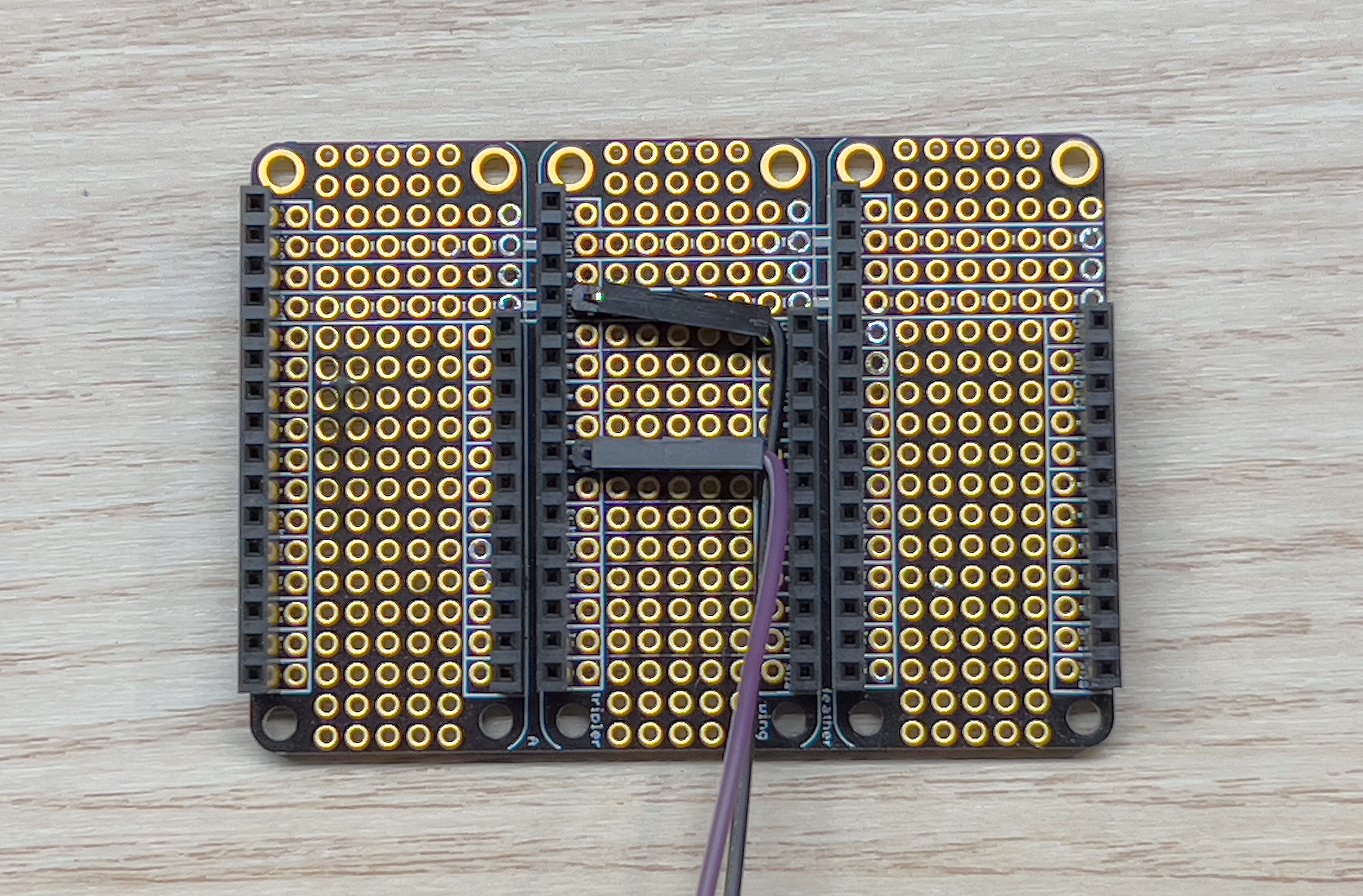
Bent Pins
Thats it! Move on to the next step!
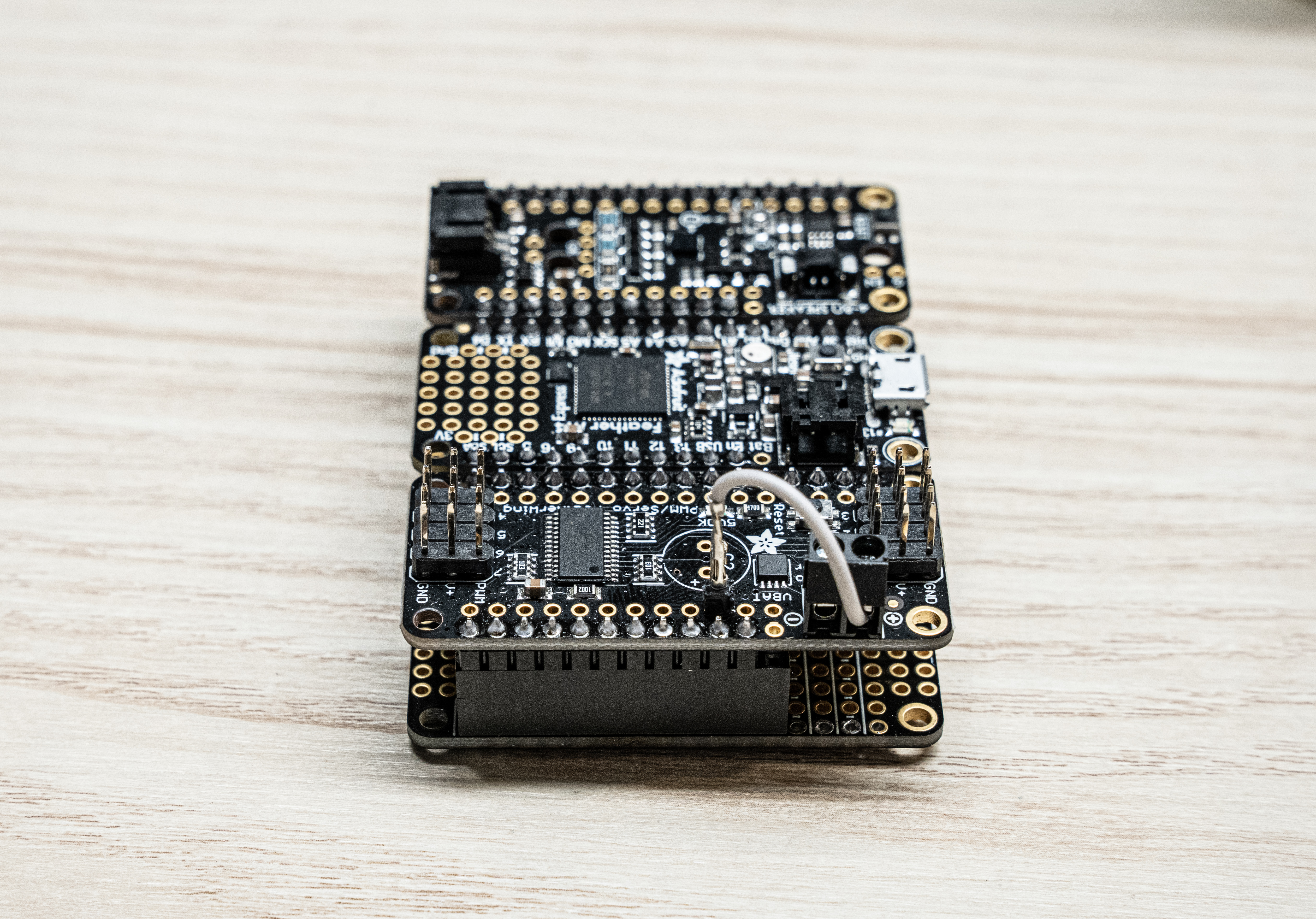
Putting It All Together
Now we can just pop the Featherwings into the Tripler as shown below:
Completed PCC
Now your PCC is assembled!
2 - Flash the PCC
Setup
To flash your PCC, you need to download and install a tool called BOSSA first.
Windows/MacOS
Go to this page and download and install
the bossa-x64-<version>.msi file for Windows, or the bossa-<version>.dmg file
for MacOS.
Make sure to install the device drivers that it prompts you to install as well.
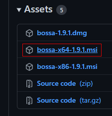
Download this installer file
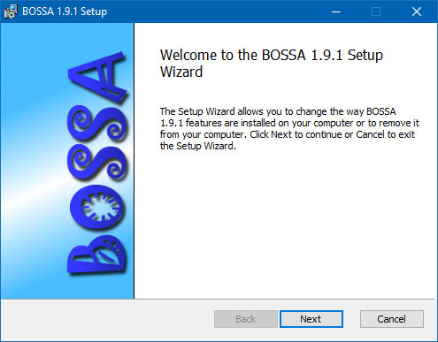
Run through the setup wizard
Linux
For Linux, you’ll need to compile and run BOSSA from source.
git clone https://github.com/shumatech/BOSSA
sudo apt install build-essential libwxgtk3.0-gtk3-dev libreadline-dev
# if libwxgtk3.0-gtk3-dev cannot be found, run `sudo apt-cache search libwxgt*`
# and install the next closest match
cd BOSSA
make -j
./bin/bossa
Flashing
After getting BOSSA installed, you need to also download the PCC firmware that you’ll
be loading. Go to the
AVR release page
and download the pcc_firmware.<version>.bin file.
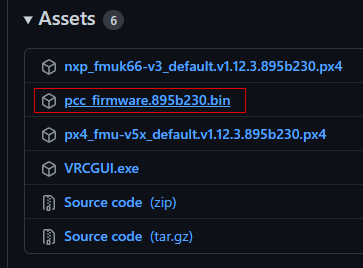
Download this firmware file
Now you’re ready to flash your PCC! Follow the next steps exactly to not run into any issues.
First, plug your PCC into your computer with the provided MicroUSB cable.
Note
Open Device Manager in Windows, and you should see at least one entry under “Ports (COM & LPT)” (if this doesn’t happen, that’s okay, it means the firmware isn’t loaded or corrupted, but we’re about to overwrite it anyways).

Normal PCC COM port
Quickly double-tap the little reset button right next to the MicroUSB connector. The LED next to the button should briefly flash red before turning solid green.
Note
Additionally, the PCC should also now show up as a USB device in Windows titled “FEATHERBOOT”, and the COM port you saw before should now be gone and replaced with one with a different number.

Bootloader PCC COM port
This puts the PCC into bootloader mode so we can flash new firmware.
Open BOSSA and select the COM port that has now shown up from the previous step,
or the serial device ttyACM0. Also select the firmware file you downloaded.
Warning
Forgetting this next step will cause lots of confusing results!In BOSSA, make sure to put in a flash offset of 0x4000 and select “Erase all”.
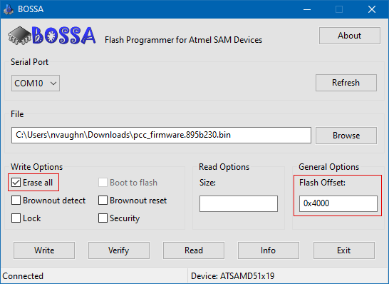
BOSSA settings
Now, you can hit the “Write” button!
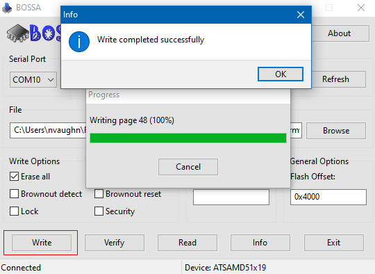
Flashing complete
You can also optionally click the “Verify” button as well just to make sure everything flashed correctly.
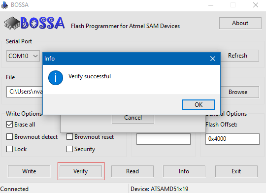
Verificiation complete
Finally, to get the PCC out of bootloader mode, and make sure the firmware is working correctly, unplug the PCC and plug it back in, or press the reset button once. The bright green LED should remain off and the original COM port should show back up in device manager.
Success
You’re now ready to test it out!3 - Test the PCC
Physical Setup
On your PCC, we’ll need to make use of a USB power jumper to power the servos from our laptop.
Installed USB power jumper
Warning
MAKE SURE to ONLY use the jumper when testing with your laptop. NEVER use the USB power jumper when the PCC is connected to the Jetson. This is because the servos may draw enough current in certain scenarios that would cause the current protection to trip on the power supply and power off the Jetson regardless of what it’s doing.
Plug your servos and LED strip into the designated connections on the PCC:
- The LED strip plugs into the prop-maker featherwing
- The servos plug into channels 0-3, with the yellow signal wire of the servo facing the Adafruit logo on the PCB.
Software Setup
Now it’s time to download the AVR GUI program.
Windows
Go to the latest
AVR software release
and download the AVRGUI.<hash>.exe file. Like QGroundControl,
you may need to bypass some warnings about being an untrusted file.
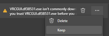
Select “Keep”
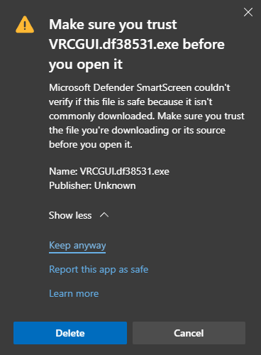
Select “Keep anyway”
Other Platforms
For Linux and MacOS, we recommend running the AVR GUI from source. You’ll need to have Python 3.9 or Python 3.10 installed.
For Linux users, here’s how you can easily install Python 3.10:
sudo add-apt-repository ppa:deadsnakes/ppa
sudo apt install python3-pip python3.10 python3.10-venv
sudo -H python3.10 -m pip install pip wheel --upgrade
For MacOS users, go to the Python releases page for MacOS and download an appropriate installer: https://www.python.org/downloads/macos/
Now, run the following commands to clone the code repository where desired, and setup the dependencies.
# clone the repo
git clone https://github.com/bellflight/AVR-2022
# cd into the repo
cd AVR-2022
# create a Python virtual environment
# You may need to replace `python` here with `python3` or `python3.10`
python -m venv .venv
# activate the virtual environment
source .venv/bin/activate
# install the dependencies
python scripts/install_requirements.py --directory GUI
# run the application
python GUI/app.py
In the future to run the application, you’ll just need to activate the virtual environment first:
cd AVR-2022
source .venv/bin/activate
python GUI/app.py
To deactivate the virtual environment, run:
deactivate
PCC Tester
Before, you launch the application, plug the PCC into your computer with a MicroUSB cable. The application will not recognize anything plugged in after it starts. Now, launch the application. You should be presented with a screen like this:
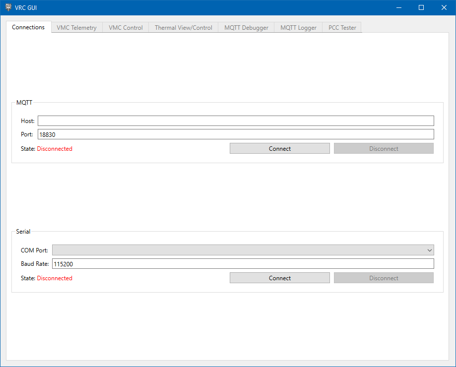
AVR GUI Home Screen
In the Serial section, select the COM Port your PCC enumerates as. Click “Connect” and the “PCC Tester” should now be enabled (we’ll talk about the other tabs in a later section).
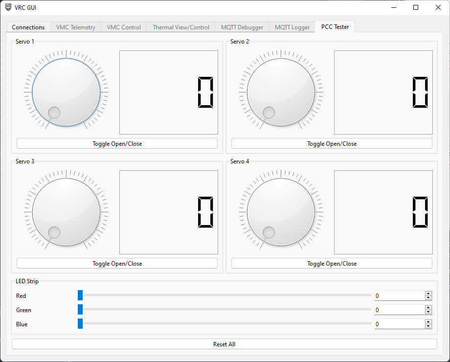
PCC Tester Tab
Click around and try the different buttons, your PCC should light up the LED and move some servos!
If some parts of the PCC work (such as the servos but not LEDs), this is likely a hardware issue. Double check all of your solder connections to make sure they are properly electrically connected and not shorting anything they shouldn’t be.
If nothing on the PCC works:
- Make sure you selected the right serial port in the GUI. Sometimes phantom COM ports show up on Windows which you will be able to select, and won’t do anything.
- Make sure your firmware flashed correctly. Follow the steps again and pay close attention.
- Finally, as stated above, double check all of your solder connections.