Control Loops
4 minute read
Control Loops
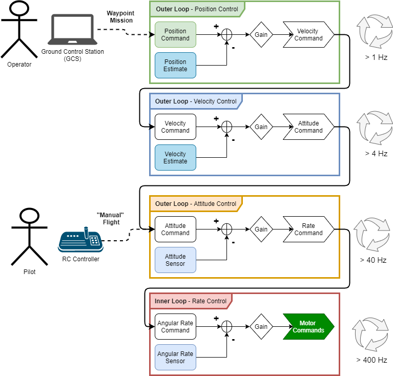
When a drone flies, there are many things going on at once, some of them are happening much more quickly than others. We can break these down as inner-loops and outer-loops.

Rate Control
This is the inner-most loop, running several hundred times per second usually. The purpose of this loop is to control the angular rate of the vehicle, that is, how quickly the vehicle is pitching forward or back, rolling to the left or right, or yawing to change its heading. If we can successfully control the angular rate of the vehicle, it is said that we are able to stabilize the vehicle. All other control loops are considered outer loops because they depend on this inner loop providing a stable vehicle.
Rate control is achieved by comparing a sensor value for the angular rate of the vehicle in each axis to a set point, or target, value. Once we have the knowledge of how far our state (pitch rate / roll rate / yaw rate) is away from where we want it to be, we can apply some gain factor (we can tune these gains to change the performance of the controller) to that difference, and we send those values to the motor controllers as motor commands. All control loops in our drone work on this principle.
Attitude Control
The Attitude control loop is the first outer loop, as its name suggests, this control loop allows us to command the vehicle to a particular attitude. If we wanted to hover, for instance, we would send attitude commands of 0 degrees, for the pitch and roll axis. It’s important to note that the output of the attitude controller is the input of the rate controller, they are effectively nested control loops. It is important to note the difference in frequency that these loops operate at; typically, an attitude loop is about an order of magnitude slower (or a division by 10) than the rate control loop.
Velocity Control
Similarly, the velocity controller compares velocity commands (usually in the form of forward velocity and vertical velocity) to a velocity estimate that has been calculated, applies some controller gain, and then computes what the desired vehicle attitude is to achieve that velocity, passing that desired attitude to the more inner loop below.
Position Control
Surely, you see where this is going. Once we can control the velocity of the vehicle, we are able to control the position of the vehicle, because velocity is merely the derivative of position, right? That is essentially true, however, we always need to keep in mind the different coordinate systems the vehicle is operating in. Almost exclusively, the coordinate frame that angular rates and attitudes are measured in is not relevant for position control, usually we want to command the vehicle to a particular latitude and longitude. How do you define a vehicle’s roll attitude in the coordinate system that latitude and longitude make sense in? There will be a coordinate transform between what position command is being set by the operator and how the vehicle interprets that before it can apply the controller.
For position control to work, the vehicle must have an estimate of where it is in space. This is where the VMC comes in, as we’ve mentioned, we are flying indoors and don’t have GPS to use a sensor, so we must find out the drone’s position with other sensors. The VMC uses two different sensors together to estimate the position of the vehicle in the inertial frame that is flying arena, that is, this frame is not moving, it is the reference for all other frames. Estimating position indoors is very challenging, and a great deal of work has been done to simplify the operation for these drones, it takes a lot of calculation and code to interface with the position sensors and generate these estimates, that’s why we have to do this work on the VMC and not the FC, the VMC is a much more powerful computer. Luckily for us, the position control loop is the slowest of the control loops, so we only have to send the position feedback to the more inner loop controls a few times a second.
←Previous Next→