This is the multi-page printable view of this section. Click here to print.
Diving Deeper
- 1: Glossary
- 2: Architecture
- 3: Control Loops
1 - Glossary
4S LiPo
4S LiPo refers to a Lithium Polymer battery that has 4 cells wired in series, which means it has a fully charged capacity of 16.8V. More info here.
CW/CCW (Clockwise/Counterclockwise)
CW stands for Clockwise and CCW stands for Counterclockwise. This refers to the direction a motor or propeller is meant to spin. A CCW propeller on a CW motor will produce lift in the wrong direction, so make sure to always double-check!
Electronic Speed Controller (ESC)
An Electronic Speed Controller controls how fast a motor spins. It receives a desired speed set-point from the Flight Controller and adjusts the power going to the motor to match the requested speed. More info on how they work here.
Flight Controller (FC) or Flight Control Computer (FCC) or Flight Management Unit (FMU)
The Flight Controller can go by many names, but in practical terms, it just a small computer that has sensors for determining the position and orientation of the drone, along with circuitry for controlling motors based on input from a pilot or autopilot. The flight controller used for the AVR (NXP RDDRONE-FMUK66) is running the PX4 flight stack, which provides basic functionality you’d expect from a hobby drone, and even some autonomy functions.
Ground Control Station (GCS)
A ground control station is an operator station from which your drone is controlled from. In our case, this will be a laptop running QGroundControl. More info here.
M3 Screw
An M3 screw is a metric screw with a 3mm diameter. This type of screw is used to build the entire X4 500 frame. More info here.
MAVLink (Micro Air Vehicle Link)
MAVLink is a standard protocol to send messages between a ground control station and an unmanned vehicle and vice versa. These messages include important information such as velocity, attitude, battery state, waypoints, etc. More info here.
MAVLink Router/MAVP2P
MAVLink Router and MAVP2P are both pieces of software that help to connect multiple MAVLink devices together. A standard MAVLink setup has a ground control station communicating directly with an unmanned vehicle, but these pieces of software allow you to connect a single ground control station to multiple vehicles or vice versa. More info here for MAVLink Router or here for MAVP2P.
Peripheral Control Computer (PCC)
The Peripheral Control Computer is a microcontroller running custom software that accepts requests from things like your laptop or, later on, the VMC to control servos and LEDs that are attached to it.
Power Distribution Board (PDB)
A Power Distribution Board is connected to your battery and takes the power coming from the battery and distributes it to the various components on your drone at the voltages and currents that they expect. More info here.
PX4
PX4 is an open-source autopilot software stack. This contains low-level algorithms running on the flight controller that constantly interpret things like position, attitude, altitude, heading, etc. and adjust the motors to keep your drone on course and can manipulate the drone to fly to desired positions. More info on PX4 here.
QGroundControl (QGC)
QGroundControl is ground-control software for drones and other unmanned vehicles. It allows you to easily connect to a drone and give it commands such as to takeoff, land, and uploading missions to it for it to perform. More info here.
R/C Controller
An R/C (radio-controlled) Controller can be used with QGroundControl to manually fly your drone while not in autonomous mode. More info here.
Vehicle Management Computer (VMC)
The Vehicle Management Computer is the companion computer that performs various tasks and communicates with the Flight Controller. This is where your custom software will be run to complete the challenges for the competiton.
Advanced Vertical Robotics (AVR)
The Advanced Vertical Robotics competition is a robotics competition put on by Bell Flight to challenge high school students to develop STEM skills outside of the classroom and work together to solve engineering challenges in a fun robotics competition in the vertical dimension.
X4 500
The X4 500 is the frame of your drone. This is what all of the components will be mounted to. More info here.
2 - Architecture
General
The software for AVR is designed around a pub/sub messaging system in order to exchange data throughout the system. This allows software modules to operate independently of each other, and to communicate with each other over a network.
A pub/sub messaging system is a system which allows clients to publish data to “topics” and clients can subscribe to incoming messages on defined topics. Think of how email works for example. You sending an email to someone is like publishing data to a topic (their email address), and you subscribe to all messages on a topic (your email address). However, a pub/sub system allows multiple clients to subscribe to the same topic.
With that in mind, the core principles of AVR software architecture are as follows:
- Data exchange must happen through the MQTT broker.
- All MQTT data must be JSON encoded.
- All modules are run as containers.
Because of all of the hardware components of AVR (PCC, FCC, thermal camera, etc.), what this generally means is that each module acts as a hardware to MQTT adapter. For example, the FCM module publishes telemetry data over MQTT, and feeds fake GPS data from MQTT to the FCC.
This modular, open system makes it simple to add new modules or functionality to AVR. The GUI for example, is 100% based on consuming MQTT data.
Modules
Here is a description of the modules in AVR and what they all do.
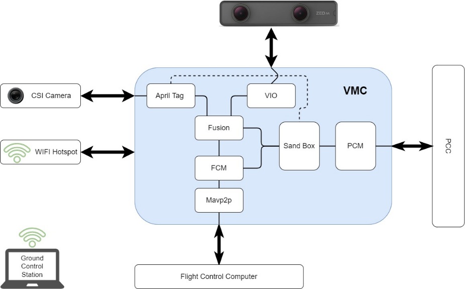
Module Flowchart
AprilTag
The AprilTag module is responsible for using the images pulled from the CSI camera to scan for visible AprilTags.
A low-level C++ program captures the images and hands them off to the Jetson’s GPU for processing and publishes the raw detections to the “avr/apriltags/raw” topic.
From here, a second Python program inside the module subscribes to this topic, and upon new detections, uses linear algebra to perform a coordinate transformation in order to get several pieces of data. These detections include the tags ID, as well as the drone’s absolute location in the court (pos_world), and the drones relative location to the tag itself (pos_rel).
This data is then broadcast out over MQTT for other modules, such as the Fusion and Sandbox modules to consume.
This is the only module with C++ code, for performance reasons.
Flight Control
The Flight Control module (FCM) is responsible for communicating with the FCC over MAVLink. This module takes telemetry data from the FCC and publishes it over MQTT. Additionally, it takes fake GPS data from the Fusion module and feeds it to the FCC.
There also exists functionality to send commands to the FCC, such as arming the drone, or sending it missions, but this is disabled due to the drone’s current lack of knowledge of where it is in global coordinates.
Fusion
The Fusion module is responsible for fusing multiple data sources to produce the final fake GPS data that is fed to the FCC. Currently, this only takes data from the VIO module, but experimental functionality exists to also take data from the AprilTag module to position itself more accurately in global coordinates.
This is the only module which is pure Python and has no hardware component.
Mavp2p
The Mavp2p module is responsible for bridging multiple MAVLink connections together. This is just a Docker container for the amazing open-source project mavp2p.
MQTT
The MQTT module is responsible for running the MQTT broker. This is a thin wrapper around the docker.io/library/eclipse-mosquitto container with a configuration baked in.
The port 18330 is used instead of the normal 1883 port because it puts it outside of the normal operating system privileged port range.
Peripheral Control
The Peripheral Control module is responsible for communicating with the PCC over serial. This is a thin MQTT to serial bridge.
Status
The Status module is responsible for consuming status information from the various other modules and updating the status LEDs connected to the VMC. This also communicates some with the host Jetson as well to check if it’s being power-limited.
Thermal
The Thermal module is responsible for capturing thermal images from the thermal camera and publishing them over MQTT.
Visual Inertial Orientation
The Visual Inertial Orientation (VIO) module is responsible for capturing data from the stereoscopic tracking camera, and converting it into global-ish coordinates.
This module considers wherever it is started as “0,0,0” and thus the drone’s movements are relative to that. Because PX4 only thinks in global coordinates, this module then uses a hardcoded latitude and longitude to convert the data into global coordinates. They’re not true global coordinates, however, as they’re still relative to where it was started.
This module is the core of the AVR “secret sauce” to enable GPS-denied stabilized flight.
3 - Control Loops
Control Loops
When a drone flies, there are many things going on at once, some of them are happening much more quickly than others. We can break these down as inner-loops and outer-loops.
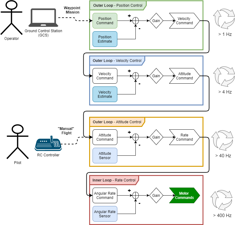
Rate Control
This is the inner-most loop, running several hundred times per second usually. The purpose of this loop is to control the angular rate of the vehicle, that is, how quickly the vehicle is pitching forward or back, rolling to the left or right, or yawing to change its heading. If we can successfully control the angular rate of the vehicle, it is said that we are able to stabilize the vehicle. All other control loops are considered outer loops because they depend on this inner loop providing a stable vehicle.
Rate control is achieved by comparing a sensor value for the angular rate of the vehicle in each axis to a set point, or target, value. Once we have the knowledge of how far our state (pitch rate / roll rate / yaw rate) is away from where we want it to be, we can apply some gain factor (we can tune these gains to change the performance of the controller) to that difference, and we send those values to the motor controllers as motor commands. All control loops in our drone work on this principle.
Attitude Control
The Attitude control loop is the first outer loop, as its name suggests, this control loop allows us to command the vehicle to a particular attitude. If we wanted to hover, for instance, we would send attitude commands of 0 degrees, for the pitch and roll axis. It’s important to note that the output of the attitude controller is the input of the rate controller, they are effectively nested control loops. It is important to note the difference in frequency that these loops operate at; typically, an attitude loop is about an order of magnitude slower (or a division by 10) than the rate control loop.
Velocity Control
Similarly, the velocity controller compares velocity commands (usually in the form of forward velocity and vertical velocity) to a velocity estimate that has been calculated, applies some controller gain, and then computes what the desired vehicle attitude is to achieve that velocity, passing that desired attitude to the more inner loop below.
Position Control
Surely, you see where this is going. Once we can control the velocity of the vehicle, we are able to control the position of the vehicle, because velocity is merely the derivative of position, right? That is essentially true, however, we always need to keep in mind the different coordinate systems the vehicle is operating in. Almost exclusively, the coordinate frame that angular rates and attitudes are measured in is not relevant for position control, usually we want to command the vehicle to a particular latitude and longitude. How do you define a vehicle’s roll attitude in the coordinate system that latitude and longitude make sense in? There will be a coordinate transform between what position command is being set by the operator and how the vehicle interprets that before it can apply the controller.
For position control to work, the vehicle must have an estimate of where it is in space. This is where the VMC comes in, as we’ve mentioned, we are flying indoors and don’t have GPS to use a sensor, so we must find out the drone’s position with other sensors. The VMC uses two different sensors together to estimate the position of the vehicle in the inertial frame that is flying arena, that is, this frame is not moving, it is the reference for all other frames. Estimating position indoors is very challenging, and a great deal of work has been done to simplify the operation for these drones, it takes a lot of calculation and code to interface with the position sensors and generate these estimates, that’s why we have to do this work on the VMC and not the FC, the VMC is a much more powerful computer. Luckily for us, the position control loop is the slowest of the control loops, so we only have to send the position feedback to the more inner loop controls a few times a second.