Overview
Motor position and rotation are incredibly important for any drone to fly properly. In your kit you will notice two motor boxes labeled CW (clockwise) and two CCW (counter clockwise). This represents the direction of rotation for each motor. Let’s revisit motor position and rotation in the image below:
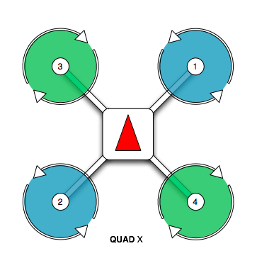
PX4 motor position and rotation
Motor positions 1 and 2 require CCW rotating motors and motor positions 3 and 4 require CW rotating motors.
You may be wondering how to determine the rotation of each motor. There are two ways to determine this. The first, and less intuitive in our opinion, is to look at the motor can. The photo below shows the motor size (2812) and kV rating (900) printed in two different formats. The kV rating for the CCW rotating motor is printed before the motor size. The kV rating for the CW rotating motor is printed after the motor size.
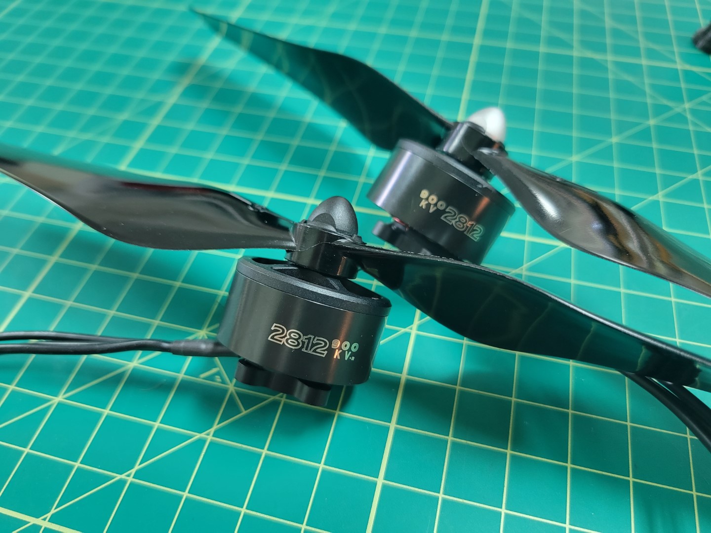
CW (black cap) and CCW (silver cap) motors
With that out of the way let’s cover a much more intutive (in our opinion) way to determine motor rotation. It requires using the propellers included in your kit. The silver capped propeller is a CCW rotating propeller and is threaded in a way that it will only screw onto the CCW motors. The black capped propeller is a CW rotating propeller. It is threaded in a way that it will only screw onto the CW rotating motors.
The photo below shows an example of installing a CW rotating propeller. Hold the propeller in place and rotate the motor in a clockwise direction. If the thread pattern is correct the propeller will screw onto the motor shaft and lock into place.
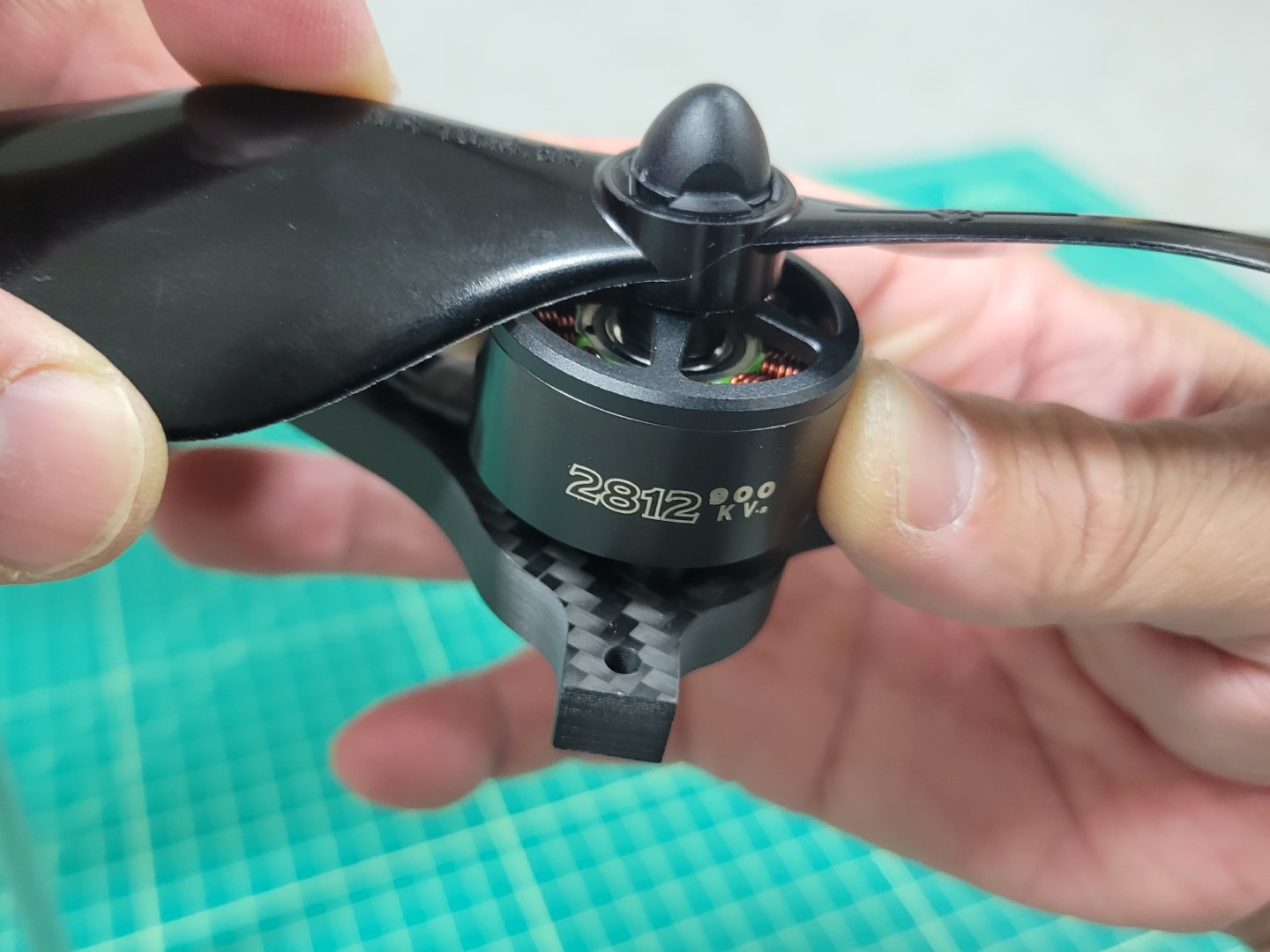
CW propeller mounting
Repeat this process for each of the four motors and then use tape to label them, just like you did with your ESC leads. You will be glad you did later!
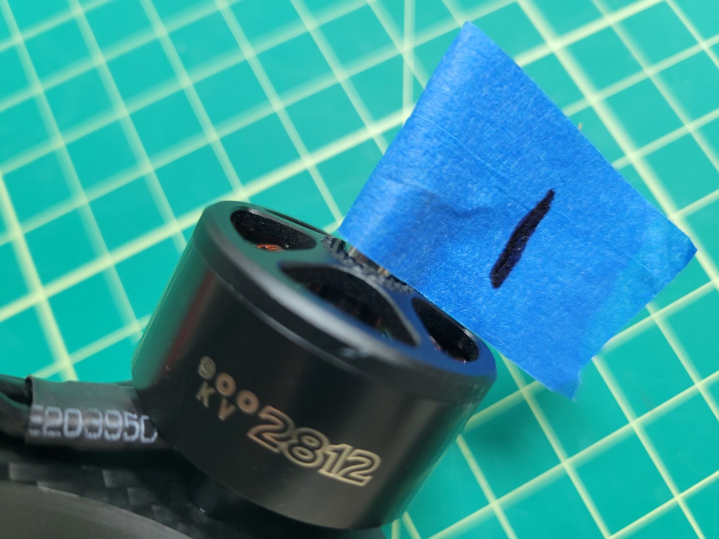
Label each of your four motors
You should have the following:
- Motor 1: CCW
- Motor 2: CCW
- Motor 3: CW
- Motor 4: CW
Attaching Motors to Arms
Inside each motor box there is a small ziploc bag of 4 x 8mm screws. In your AVR kit you will also find a ziploc bag of M3 washers.
Warning
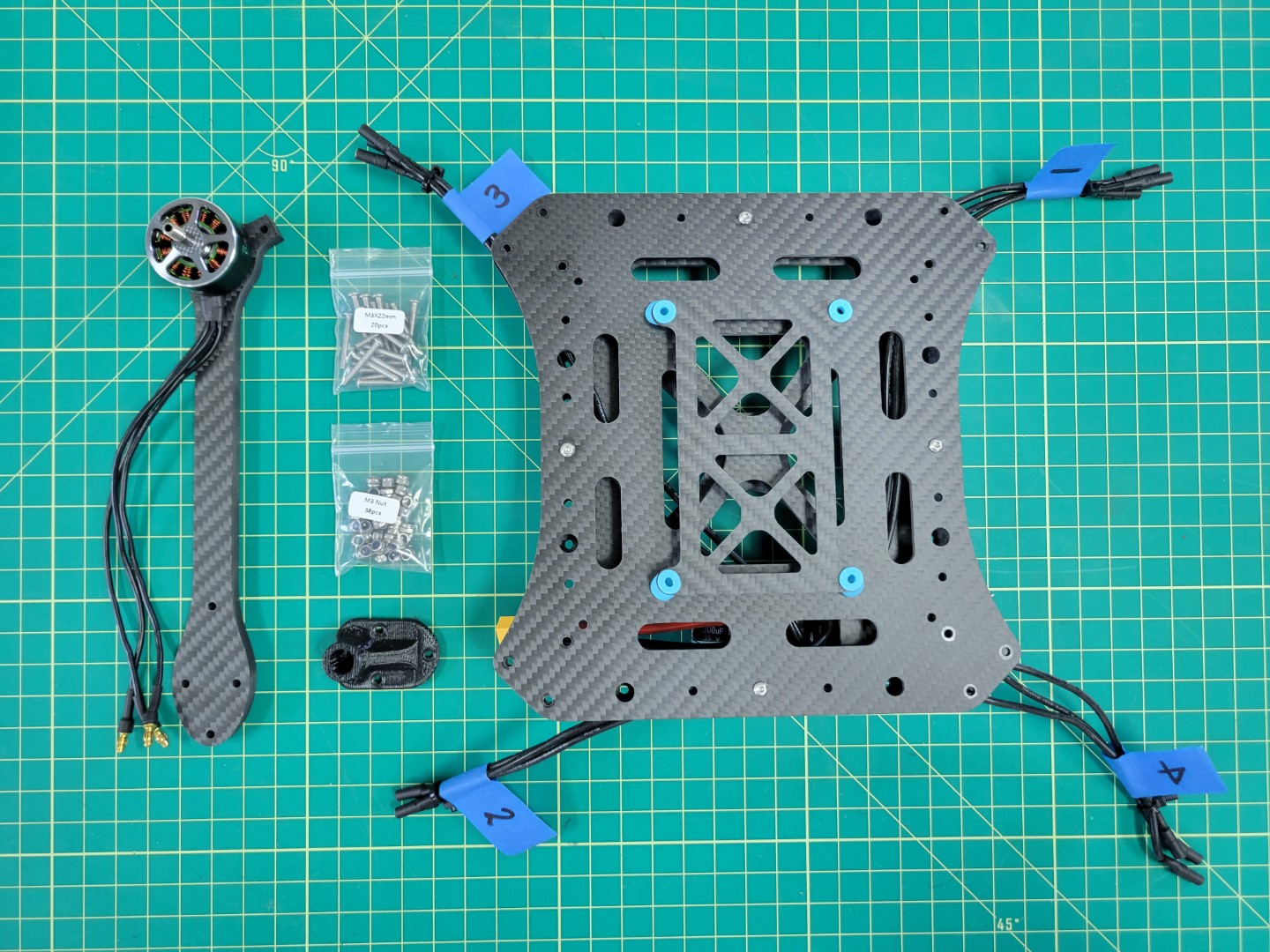
Please be sure to use the screws provided in the small ziploc bag inside the motor box. Using longer screws from the kit can end up damaging the motor windings and ultimately prevent the motor from operating.The photo below shows the necessary parts for mounting the motor to the frame arm. You will follow this procedure for each of the four motor/arm assemblies.
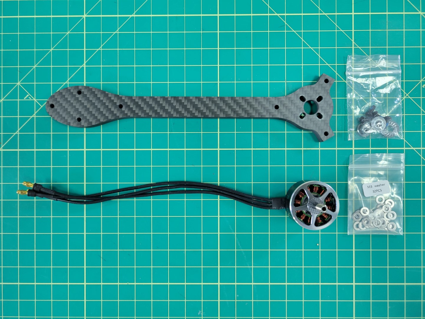
Parts necessary for mounting each motor
A 2mm hex driver is necessary to secure each of the 8mm screws into the motor.
Warning
Don’t forget to use one M3 washer with each screw. This will help reduce stress on the carbon fiber arm.Place a small drop of blue Loctite on each screw as shown in the photo below.
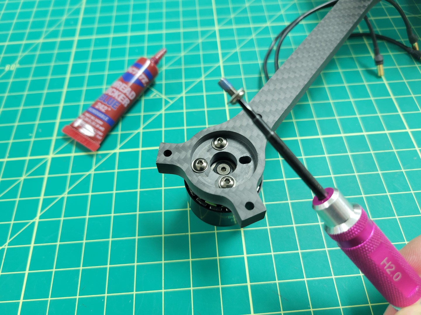
Blue Loctite on motor screw
Loctite is useful in helping secure your screws and prevents them from coming loose.
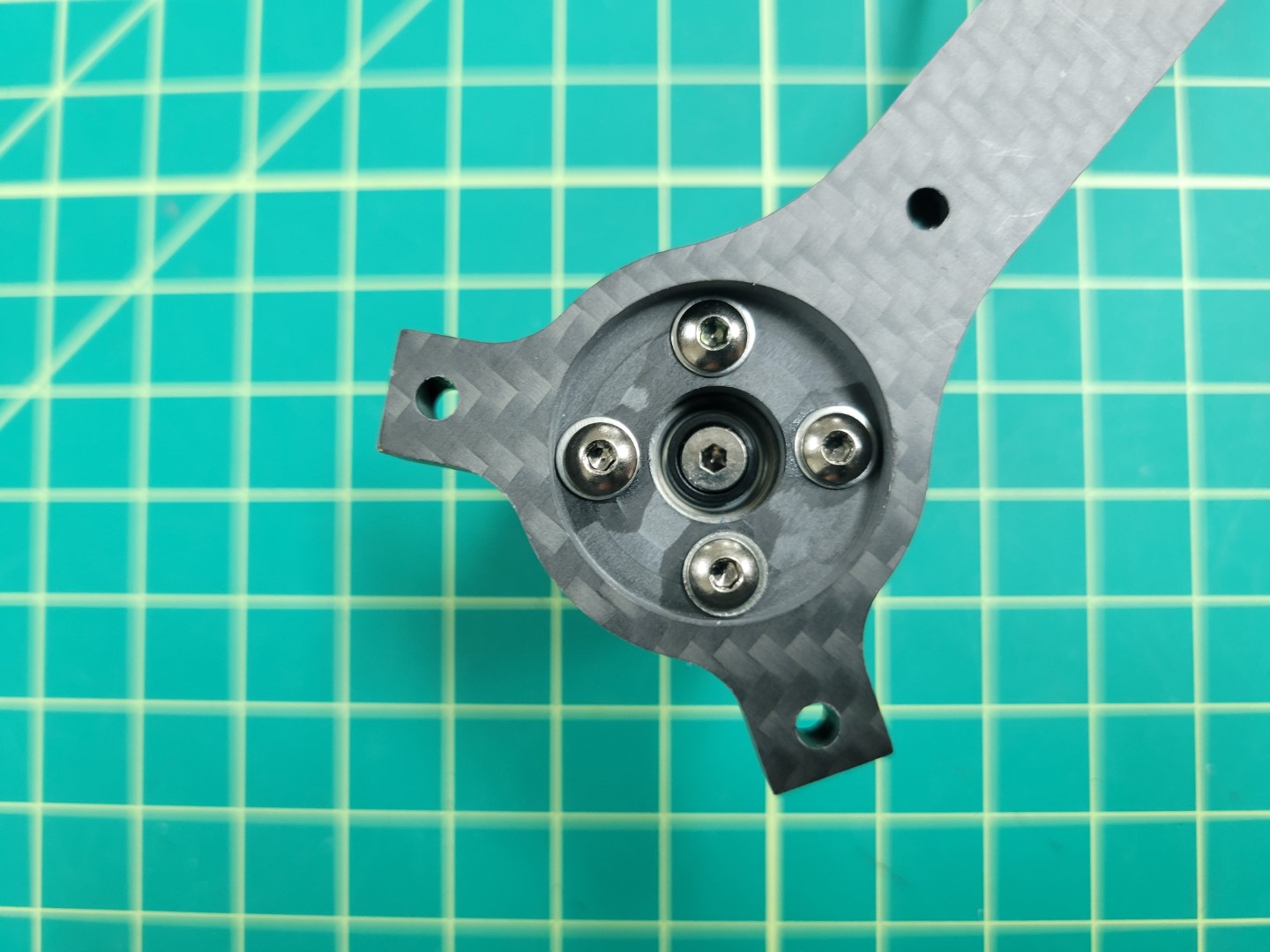
Motor mounted and secured
Repeat this process for all four of the motors.
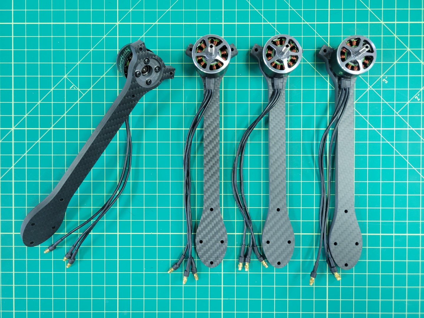
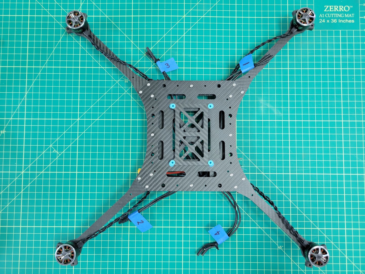
All four motor/arm assemblies complete
Attaching Arms to Midplate
Note
To proceed with this step you must 3D print four landing gear mounts. Make sure to print with 100% infill as these mounts will experience a lot of stress from the weight of the drone and hard landings.Locate the M3 22mm screws and lock nuts in your AVR kit. These will be necessary for mounting the motor arms to the midplate and securing the 3D printed landing gear mount.
Parts for motor arm mounting
Each arm will require three 22mm screws and lock nuts. You will insert each of the screws through the top plate, arm, bottom plate, and landing gear mount. The lock nut will be secured from the bottom as shown in the photo below. A 5.5mm box driver is necessary for tightening the nut. Be sure to tighten each nut securely.
Tip
Save yourself some trouble and make sure that the motor arms are mounted in the right position. Make sure that the labeled ESC leads match with the motor labels. Refer back to the PX4 motor image above if necessary.
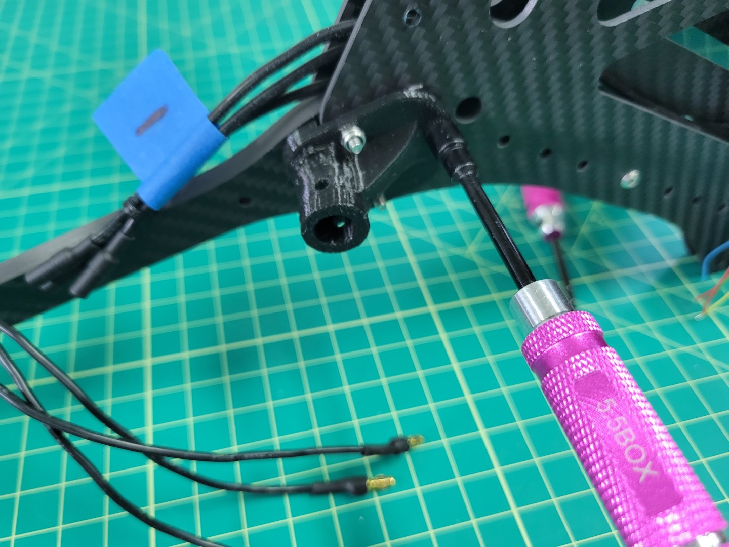
Securing lock nuts with 5.5mm driver
Repeat the installation process for each motor arm.
All four motor arms secured
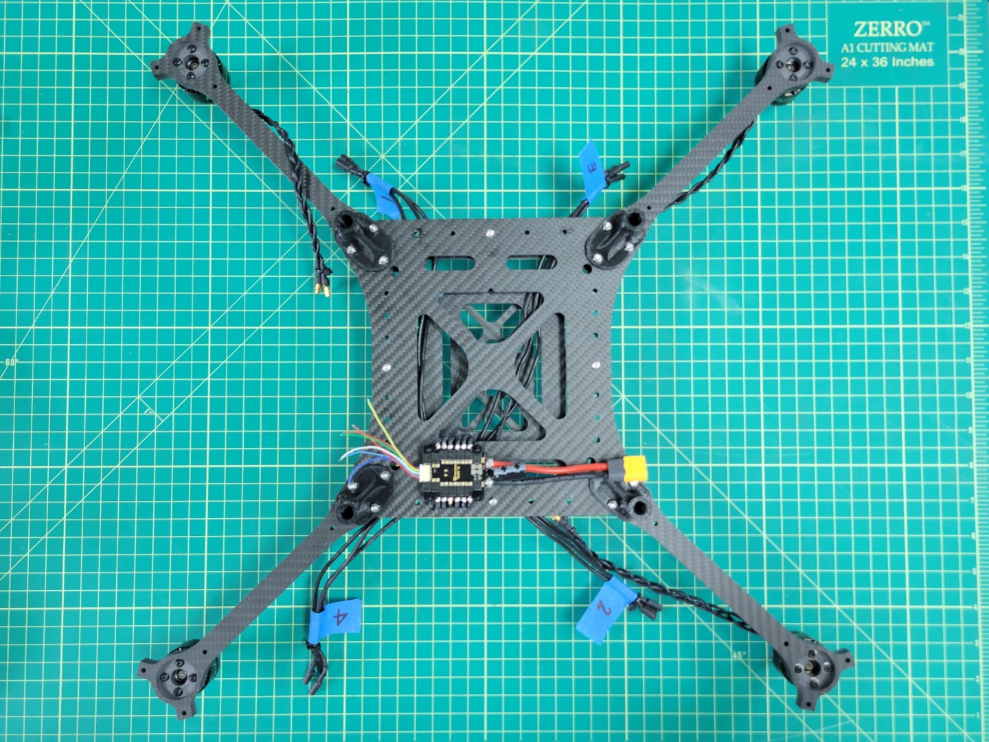
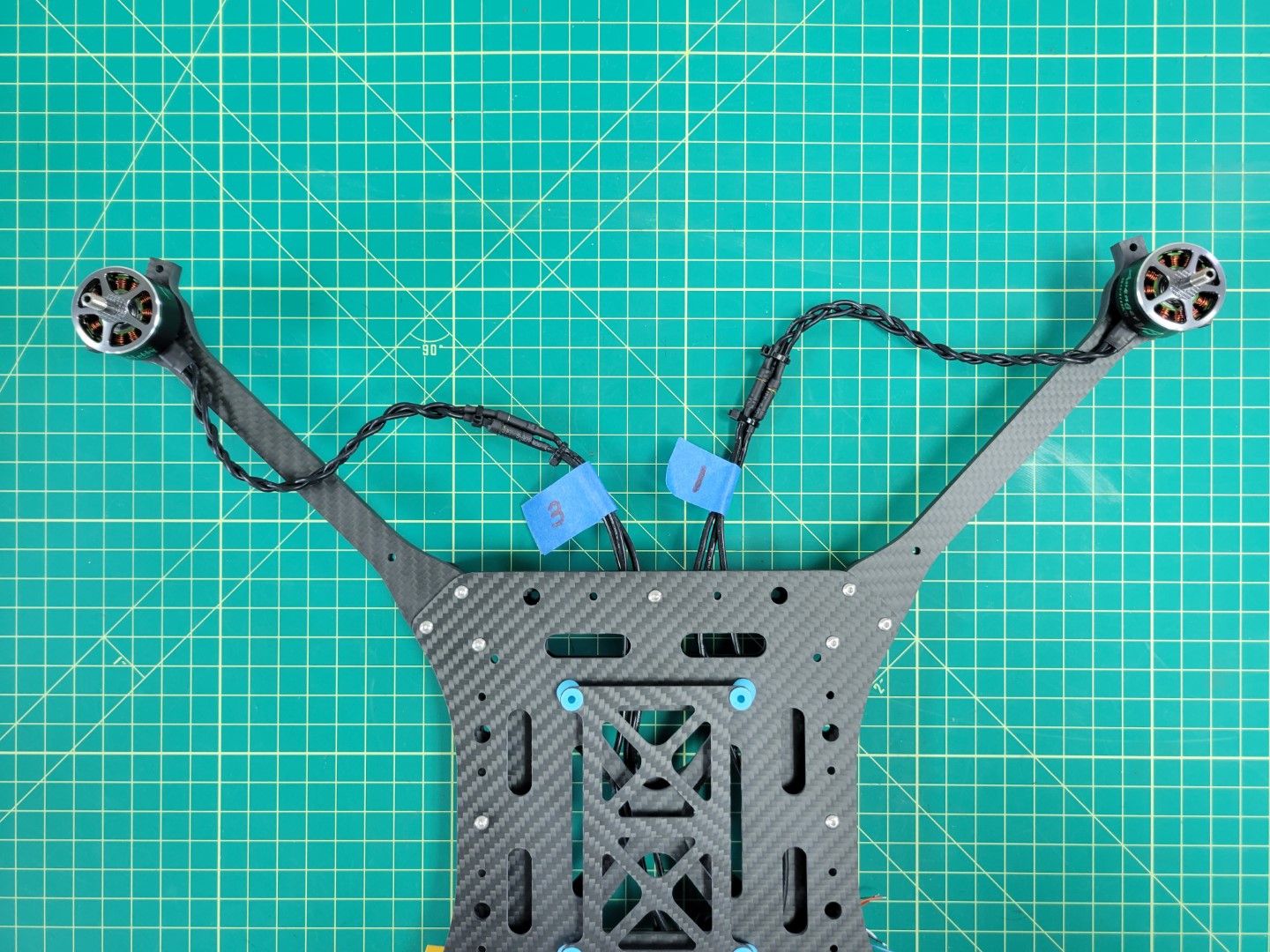
Flip your AVR drone over and connect each of the motor leads to the corresponding ESC leads.
Motors and ESCs ready to be connected
Be sure to make a good connection between the male leads of the motor to the female leads of the ESC. You should not see any brass between each of the connections. This is important so that nothing comes loose or causes a potential short.
Motors and ESCs all wired up
Feed any excess cable slack between the top and bottom plates. You can use zip ties to clean up your cabling as shown in the photo below.
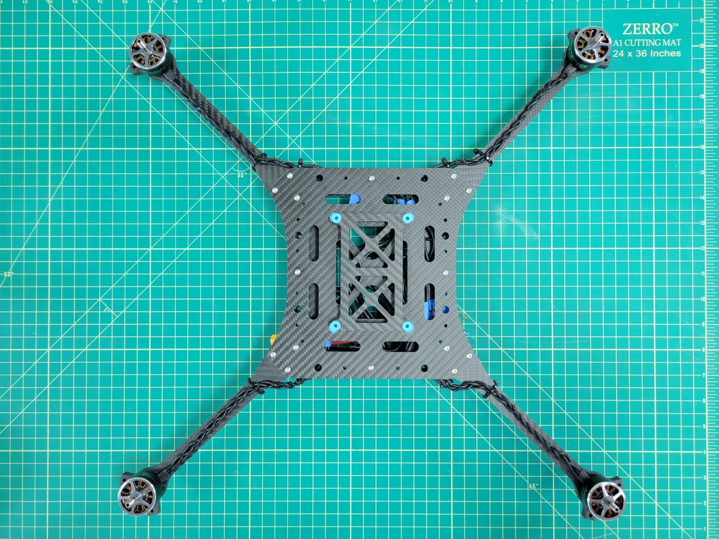
Zip ties keep you build nice and tidy
Motor position and rotation is an important part of any drone build. The photo below is a gentle reminder. It won’t be long before you have this photo memorized!
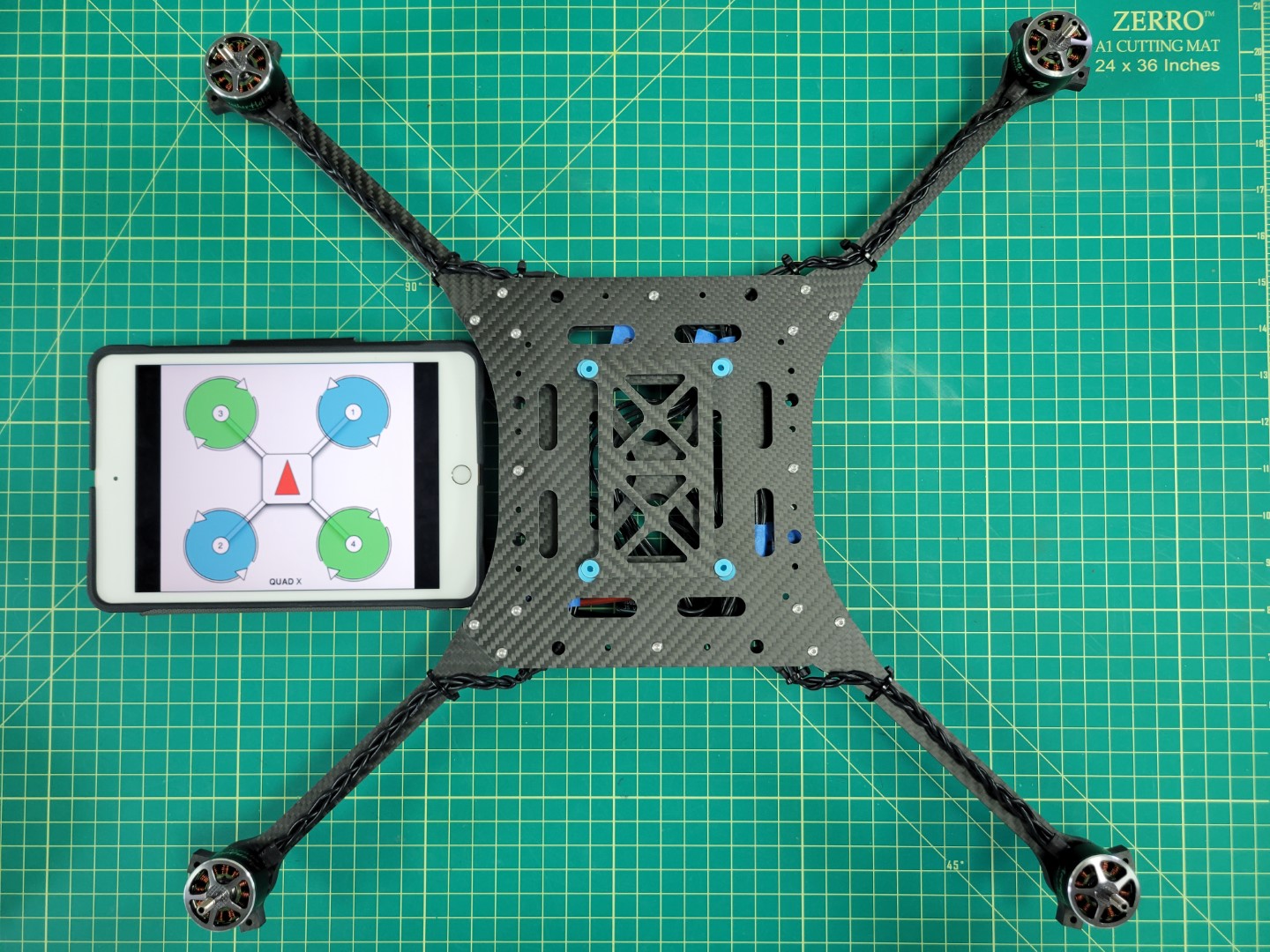
Motor position and rotation