This is the multi-page printable view of this section.
Click here to print.
Return to the regular view of this page.
Basic Drone Assembly
This section guides you through the assembly of the drone kit
This section is a complete guide on how to build the Bell AVR drone.
It is recommended to read this guide thoroughly and in order.
At the bottom of each page, there are navigation buttons that will allow you to
proceed to the next section or visit the previous one.
Our goal in this section is to get you to Checkpoint #1: Flight Test,
which consists of the ability to manually pilot the drone indoors in a
stabilized flight mode.
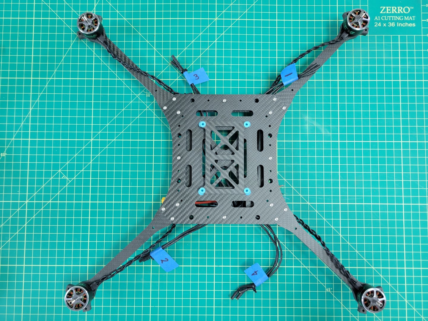
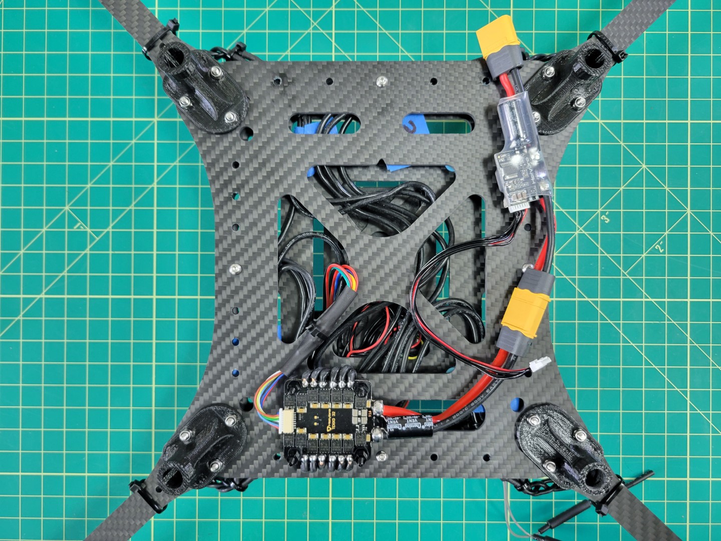
Below are photos of what your assembled kit will look like before your
first flight test.
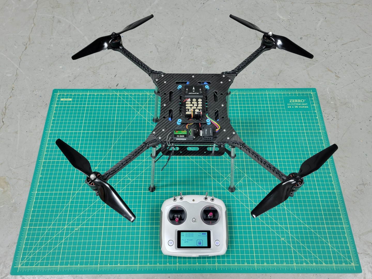
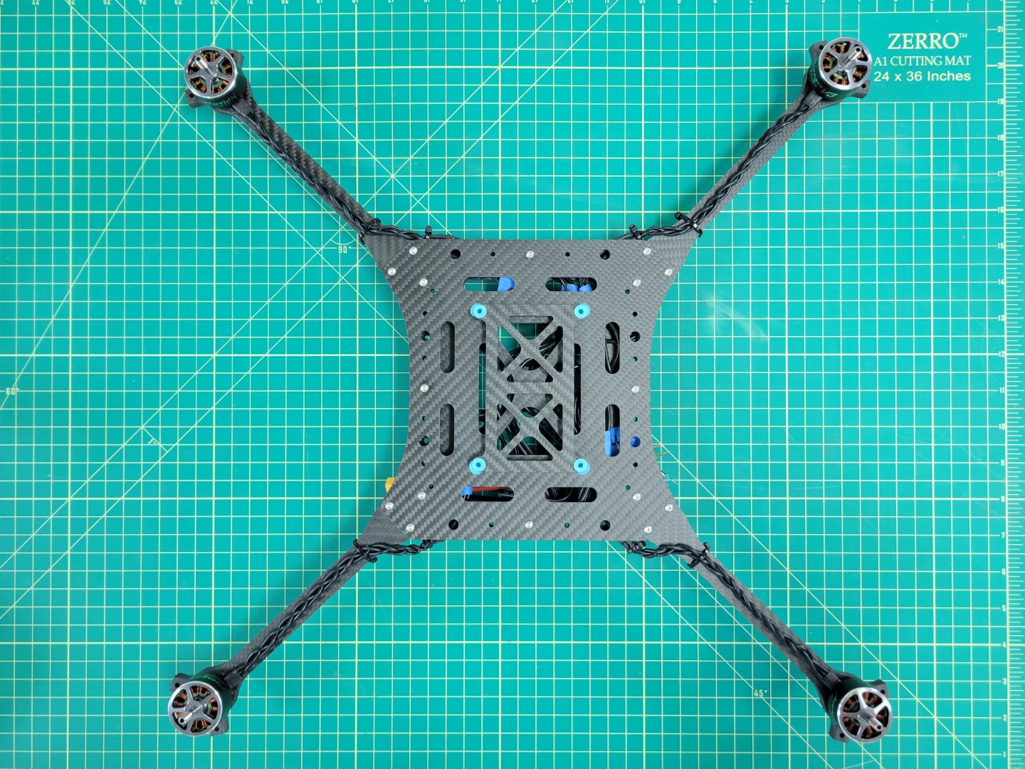
AVR drone ready for first flight
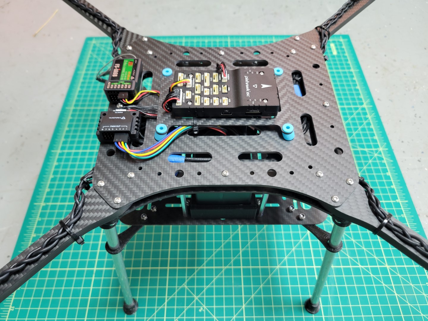
AVR drone right side view
A simple block diagram can be used to represent the components of the basic drone.
As you move throughout this documentation keep these details in mind.
It will help you gain a high-level understanding of what we’re trying to accomplish.

Block diagram of basic drone components
Let’s get started with assembly!
1 - ESC Mounting
This page will explain how to mount the 4-in-1 ESC to the midplate
Mounting
Note
As you work through each section of the AVR build process we highly encourage you to read to the bottom. Then come back to the top and begin building!
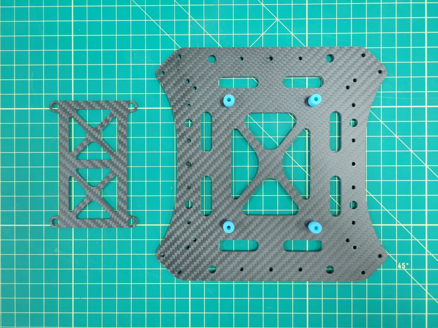
The Tekko32 4-in-1 ESC will be mounted underneath the bottom plate of the middle section. Locate the bottom plate as shown in the photo below. You will notice a small notch that indicates the front of the plate.
Look for the 6mm threaded nylon standoffs and bolts that will be used to mount the ESC. It’s important that the electronics from the ESC do not make contact with the carbon fiber plate. This could lead to a potential electrical short.
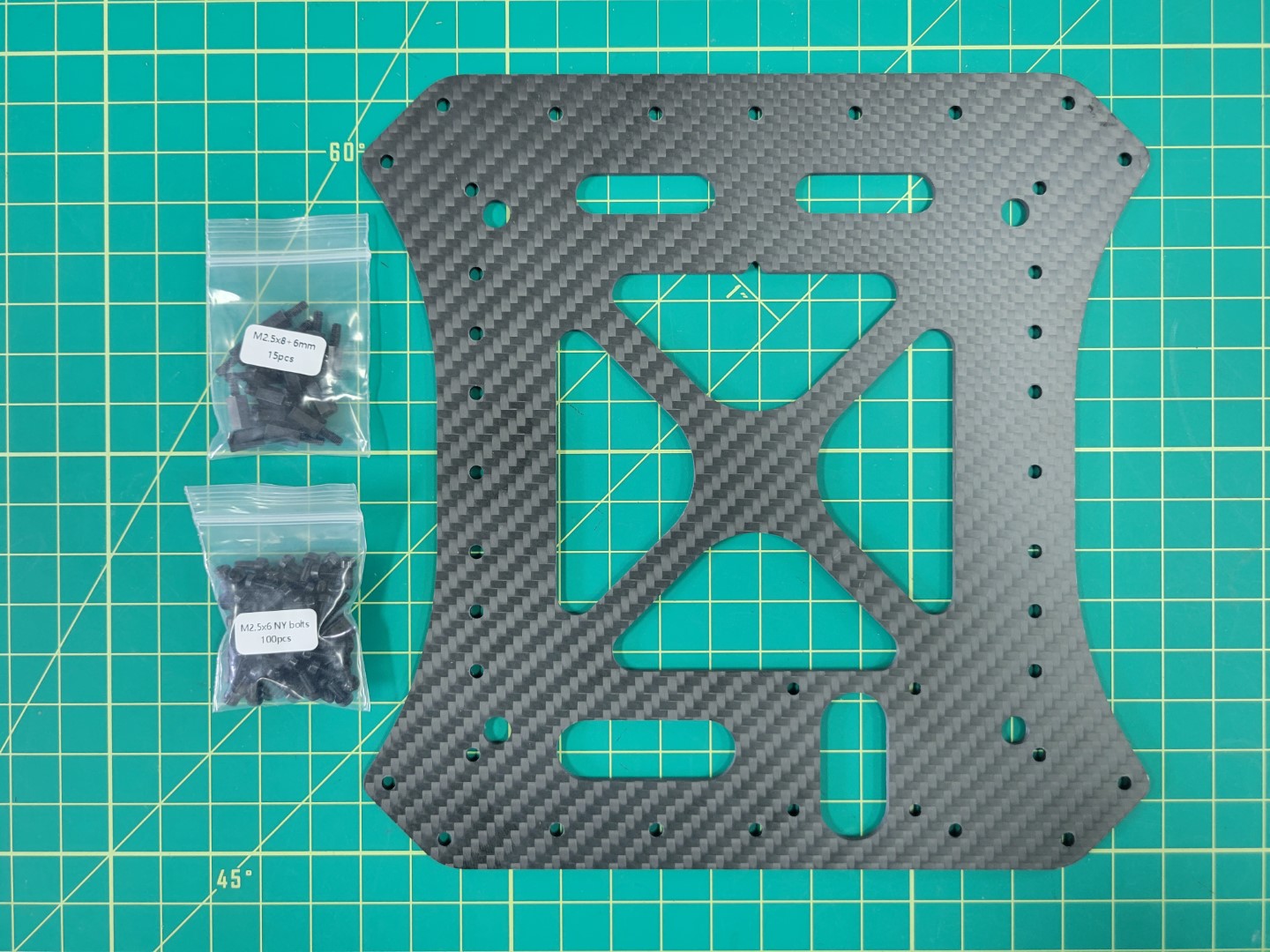
Mid bottom plate with nylon hardware
Your AVR kit comes with a small tube of blue Loctite. You’ll want to place a small drop of this inside each of the threaded standoffs. Don’t overdo it. Loctite can get messy and a little will go a long way.
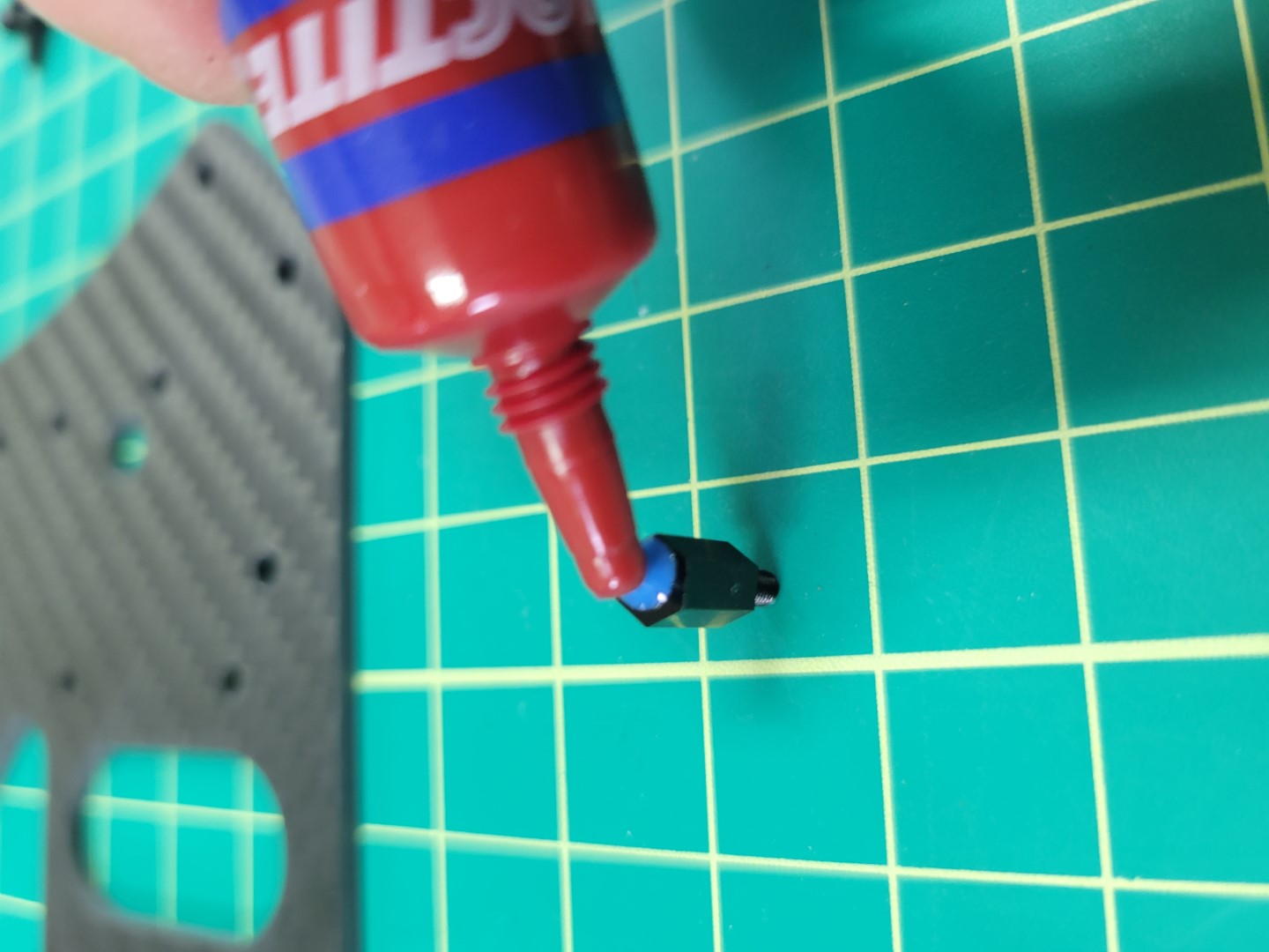
Applying blue Loctite to 6mm nylon standoff
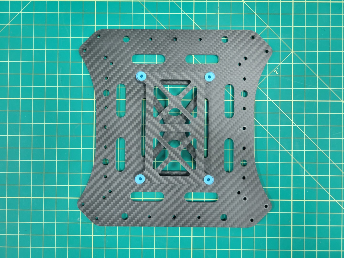
Mount the standoffs in the right rear corner of the plate facing downward as shown in the photo below.
Warning
Be careful not to overtighten. Nylon hardware is easy to strip. Gently tighten and let Loctite do its job. Loctite will set in about 10 minutes and fully cure after 24 hours.
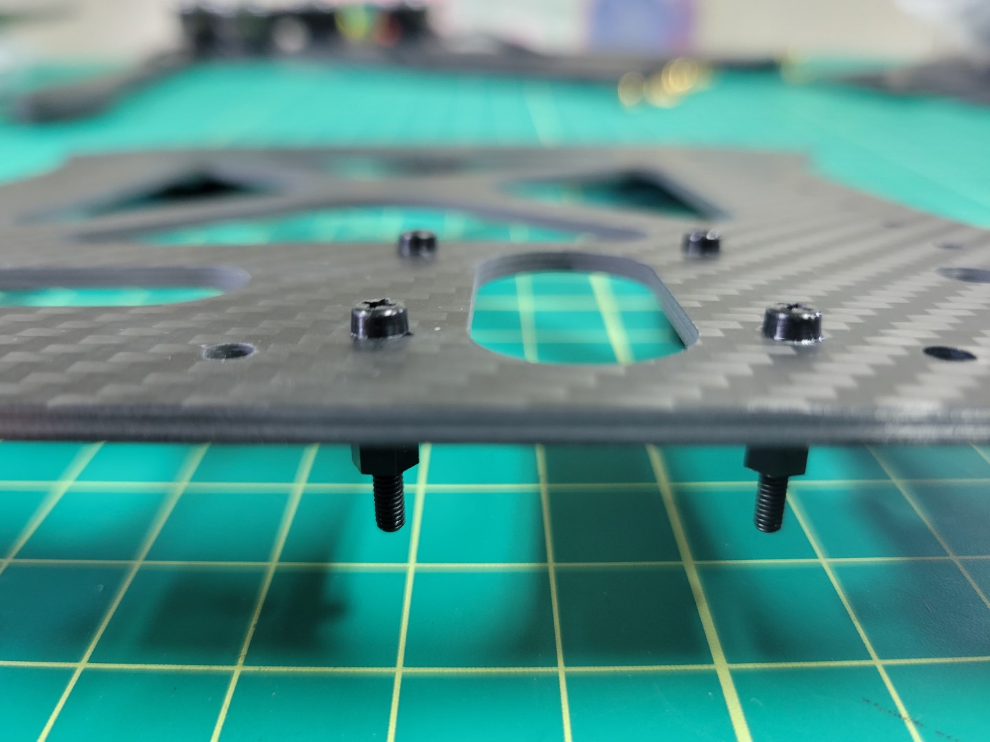
Nylon bolts and standoffs in place
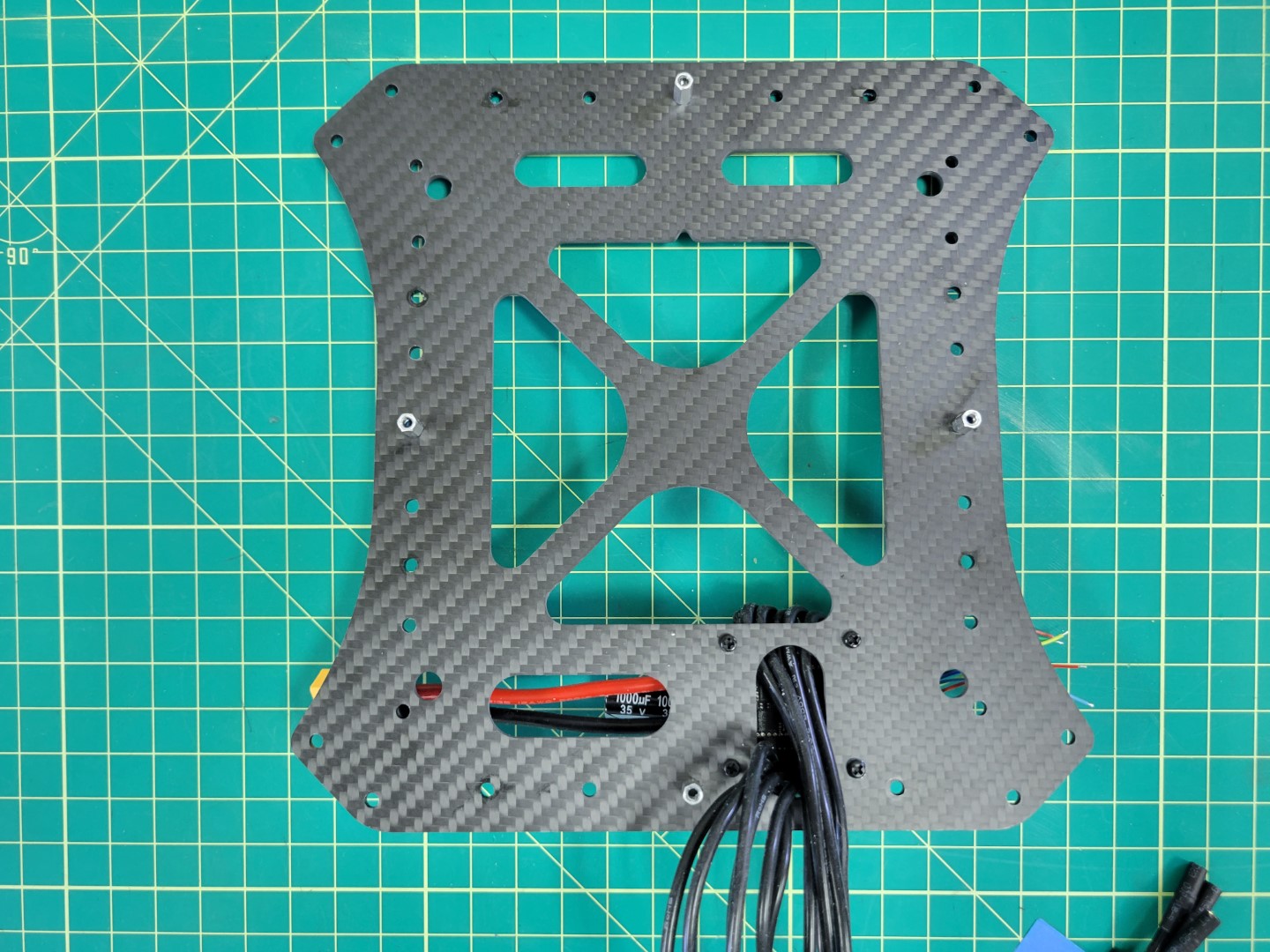
Flip the plate over so that the threaded standoffs are facing up. Run all of the ESC leads through the provided cutout.
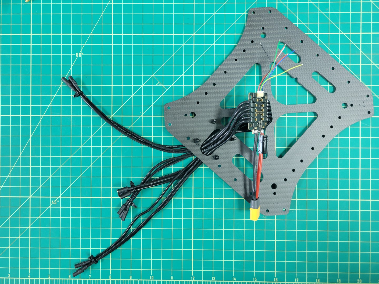
Feeding ESC leads through the plate
Warning
Use care when feeding the ESC leads through the cutout. Edges of carbon fiber can be sharp and you do not want to accidentally strip any of the shielded cables.
Before placing the ESC on the standoffs you will need to install the rubber dampeners. You can find these inside a small ziploc bag in the ESC packaging.
The purpose of these rubber dampeners is to keep the ESC secure when placed onto the nylon standoffs.
ESC dampeners prior to installation
Working with rubber dampeners can sometimes be a bit challenging. We recommend using a tool with a flat tip such as a 2.0mm hex driver that you will be using throughout the AVR build process. Do not use a sharp or pointy tool such as a Phillips head screwdriver. You do not want to accidentally pierce the rubber dampeners.
Pinch the dampener and feed it into the hole with your fingers. Use the hex driver to push the rim of the dampener into place as shown in the photo below. Repeat the process for all four corners of the ESC.
Using a 2.0mm hex driver to install rubber dampener
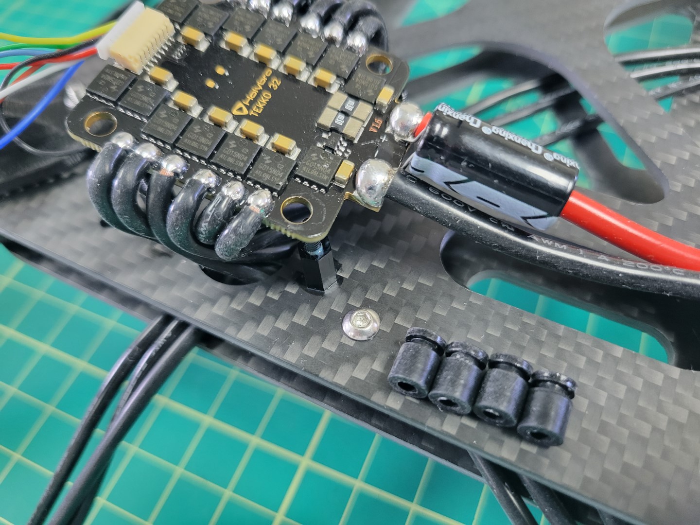
Once all the dampeners have been installed proceed to place the ESC on the standoffs. You will need to use a bit of force to push the ESC into place.
Make sure the yellow XT60 connector is facing the towards the inside of the plate and not hanging off the edge.
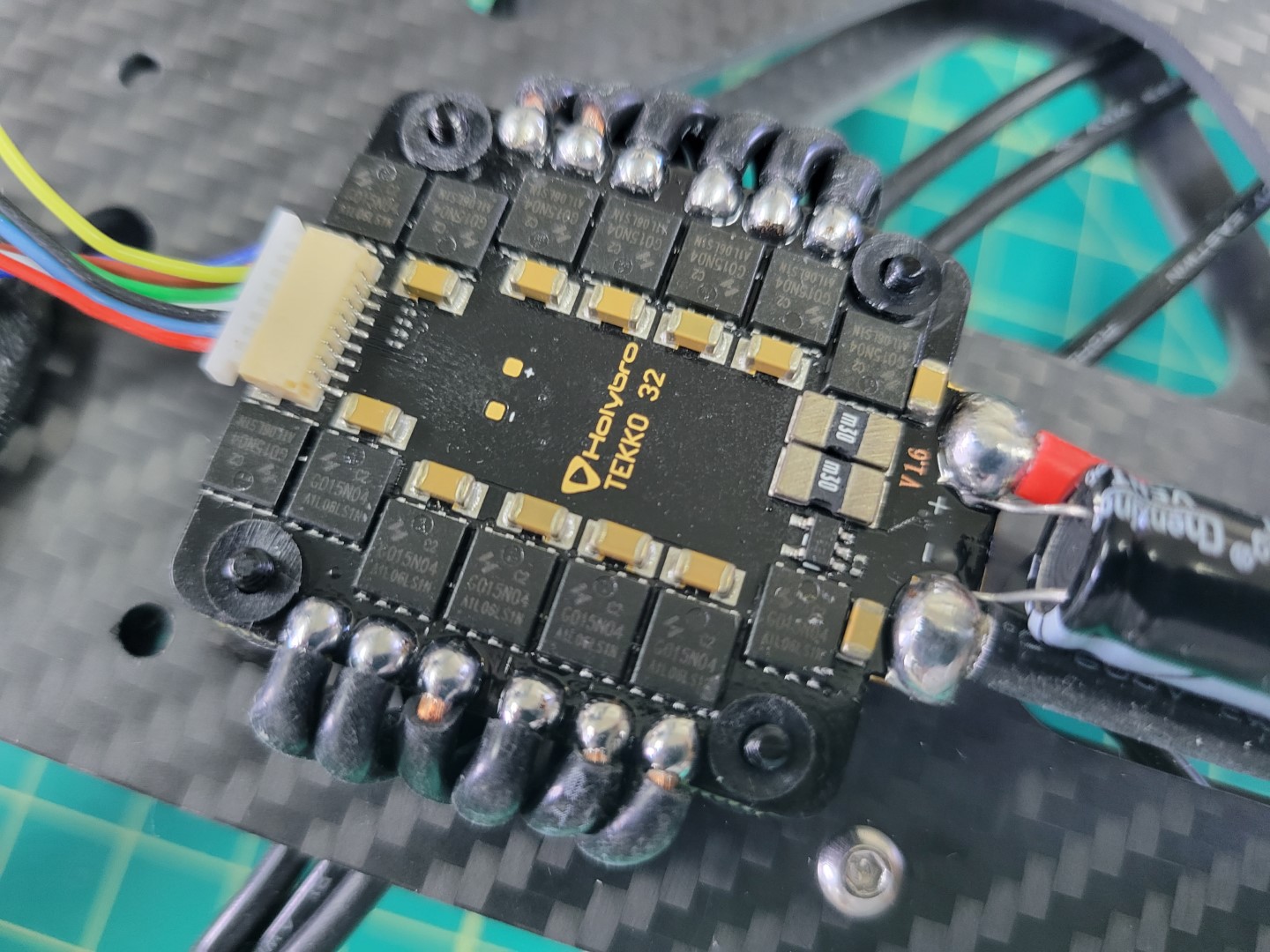
ESC placed onto 6mm standoffs
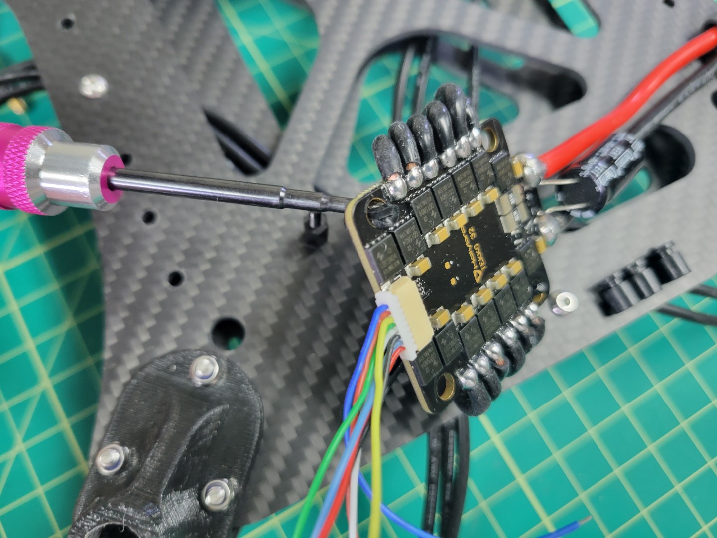
Now that the ESC is in place use four more 6mm threaded standoffs to secure it. In the next phase of the build process you will “stack” a Power Distribution Unit (PDU) on top of the 4-in-1 ESC. Don’t forget to use a dab of Loctite on the standoffs.
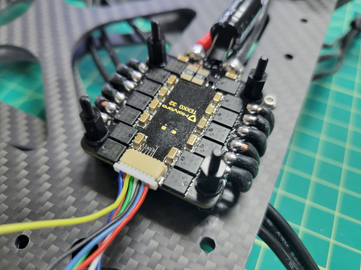
ESC secured with standoffs ready for PDU
ESC mounting is complete! Before proceeding we recommend following the tip below.
Tip
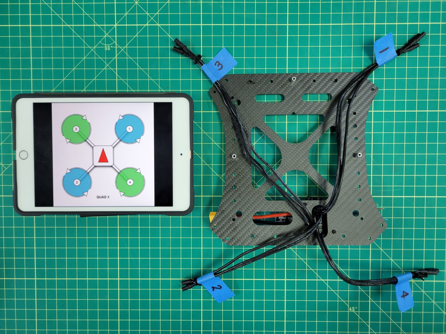
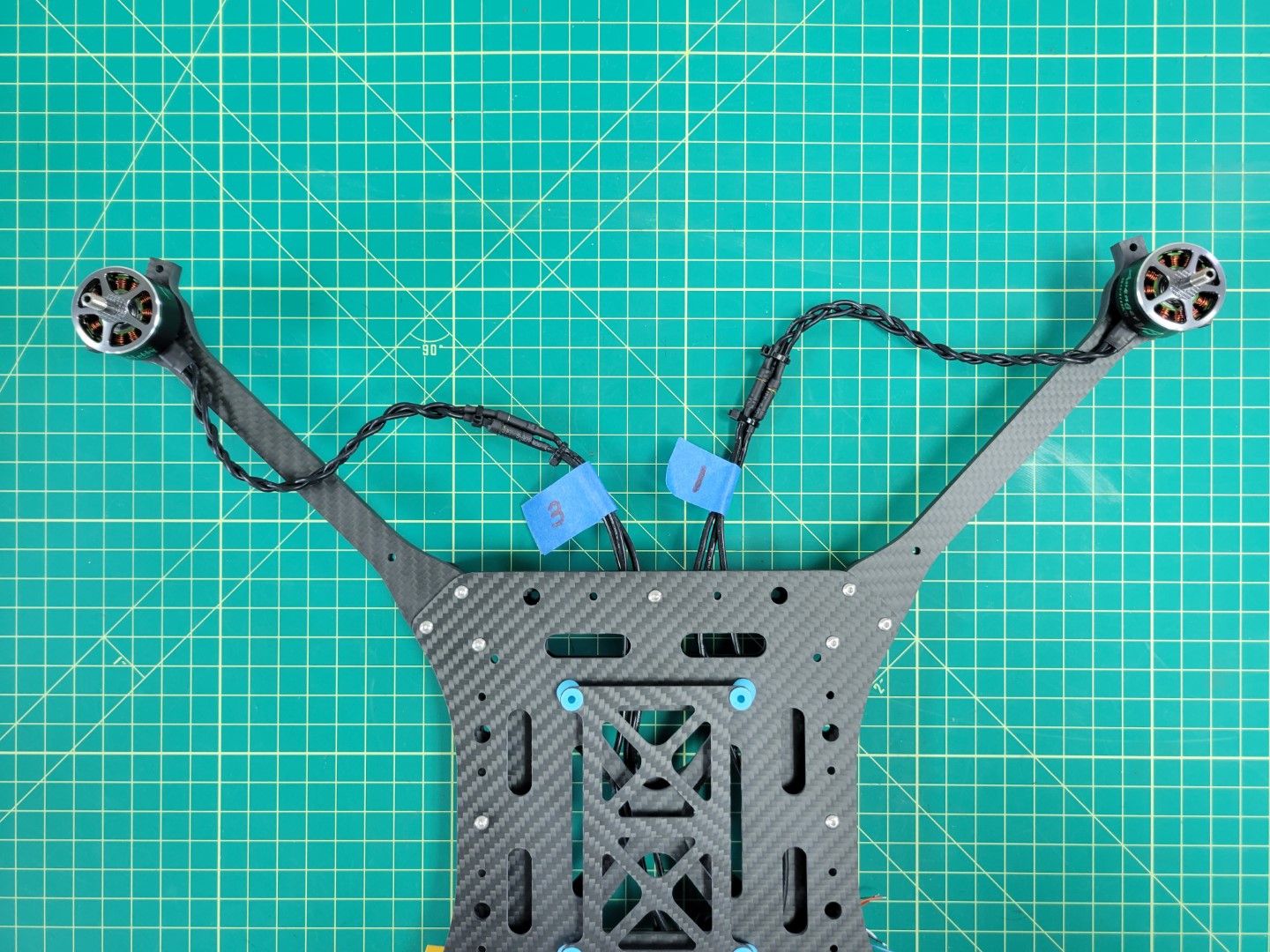
Labeling your ESC leads will save you time and frustration throughout the build! The diagram below shows how each group of three ESC leads match up with motors M1-M4. In the next section we will install the middle top plate, which will make it challenging to see which lead goes to a given motor. Do this step now and you will be glad you did!
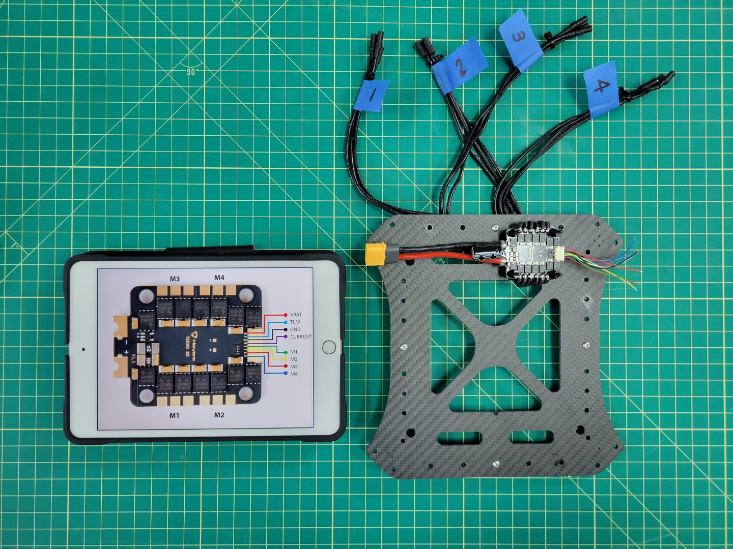
Labeling ESC leads saves time and frustration
2 - Mid Plate Assembly
The mid plate assembly is an essential part of the AVR frame. It holds the motor arms, ESC leads, and Pixhawk FC.
Standoff Mounting
We will be mounting the mid top plate to the bottom plate using M3x8mm standoffs and M3x6mm screws. Make sure your parts match up with the photo below.
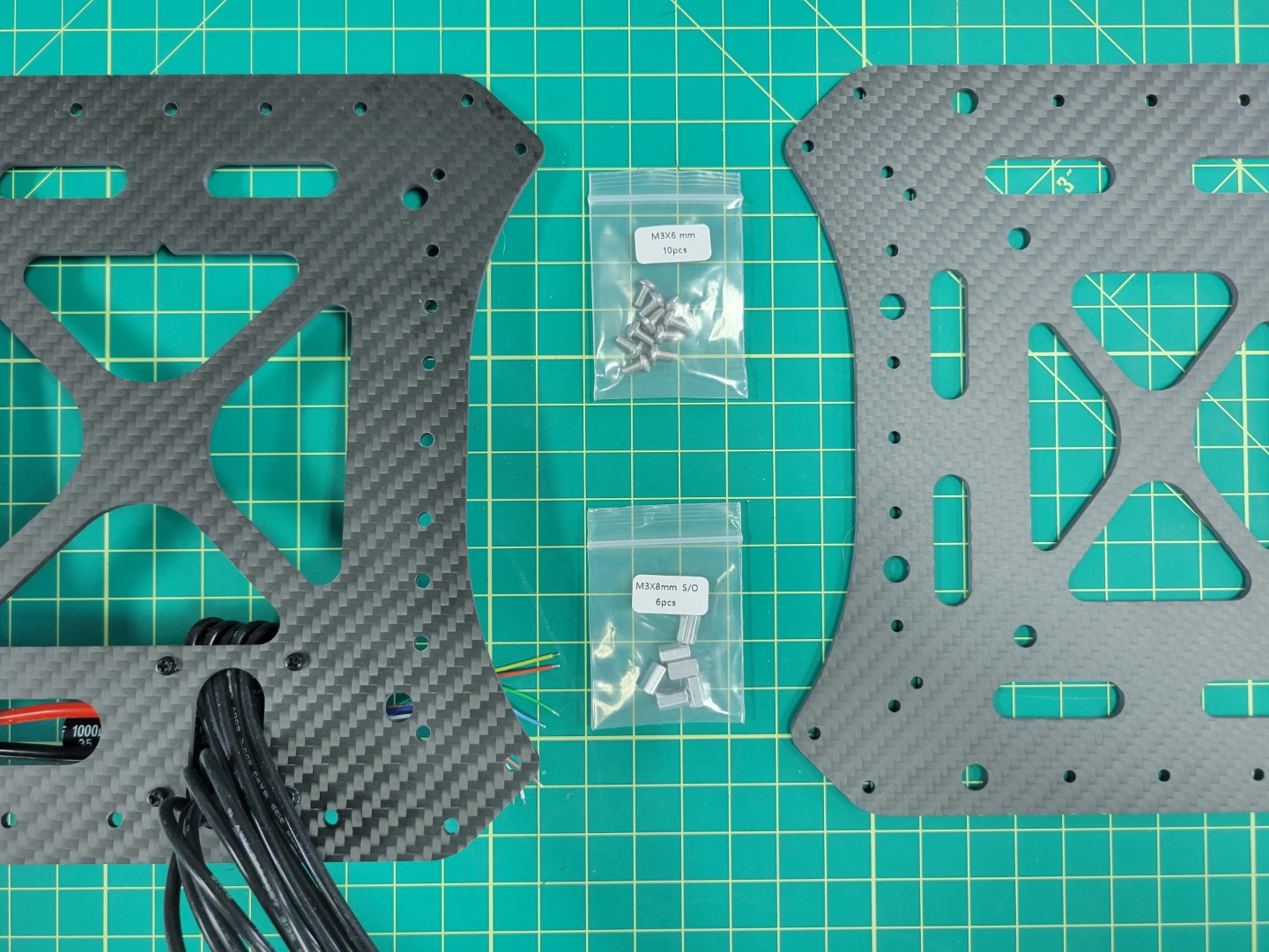
Mid plates with 8mm standoffs and 6mm M3 screws
The mid bottom plate has several mounting holes around the outside edge. Locate the center hole on each edge of the plate. Place a screw in each hole.
Note
Make sure you are placing the screws through the plate on the same side as the ESC. Take a close look at the photo below for more guidance.
Standoff with Loctite
A small dab of Loctite in each of the standoffs will help keep the plates secure. Screw each of the standoffs into place with a 2.0mm hex driver.
All four standoffs secured to mid bottom plate
Pixhawk FC Tray Mounting
Before securing the mid top plate we will mount the Pixhawk Flight Controller (FC) tray with four rubber dampeners. This is necessary to help isolate the FC from vibrations that are generated from the propellers.
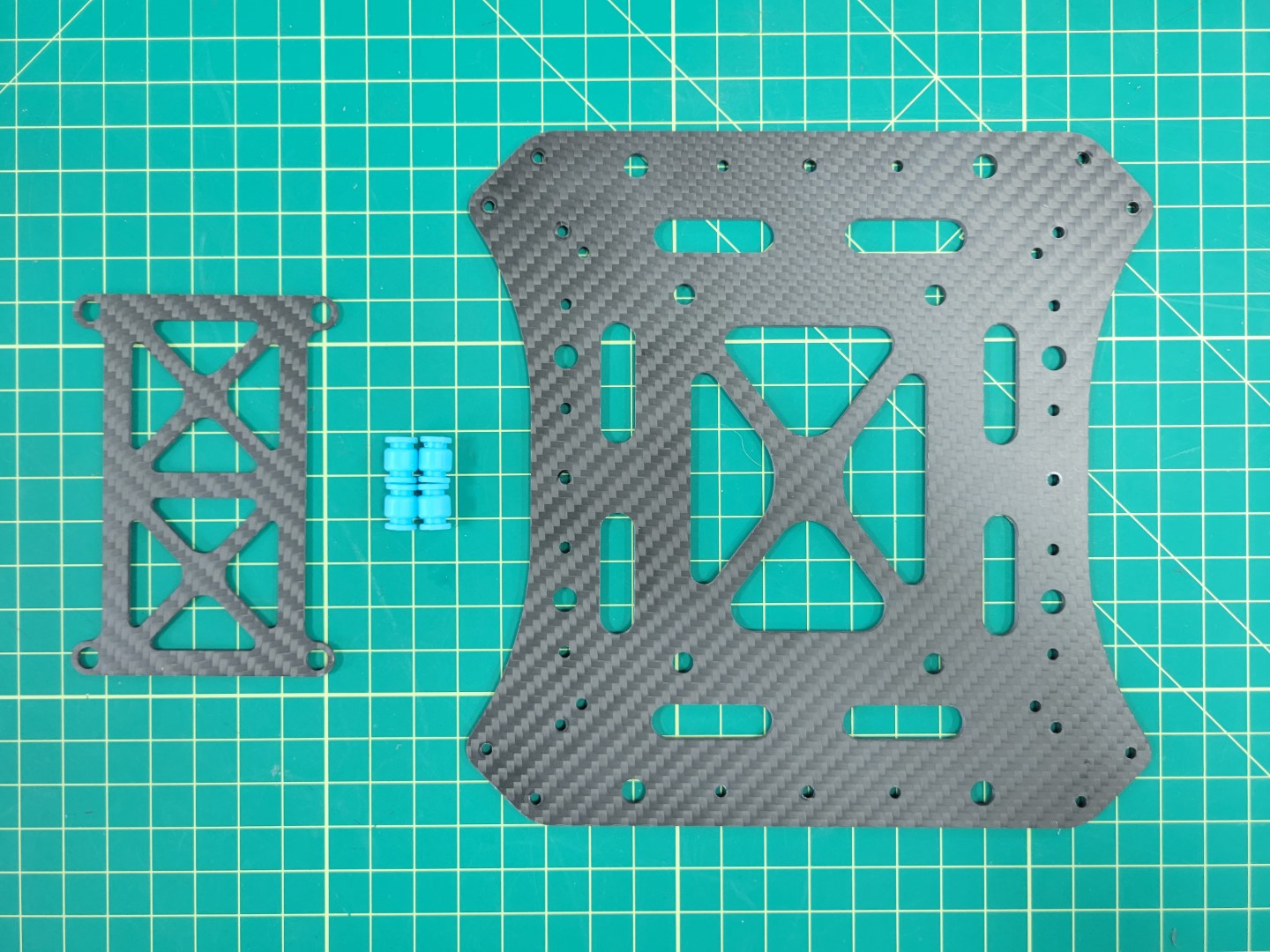
FC tray, dampeners, and mid top plate
The following steps show installing the dampeners in the top plate first, but some prefer installing them in the tray and then attaching the tray to the top plate. Choose whatever method makes the most sense to you.
Use the same procedure as mounting the ESC dampeners. Pinch the dampener, push it into the hole, and use your 2mm hex driver to feed it through the plate. Do this for all four dampeners.
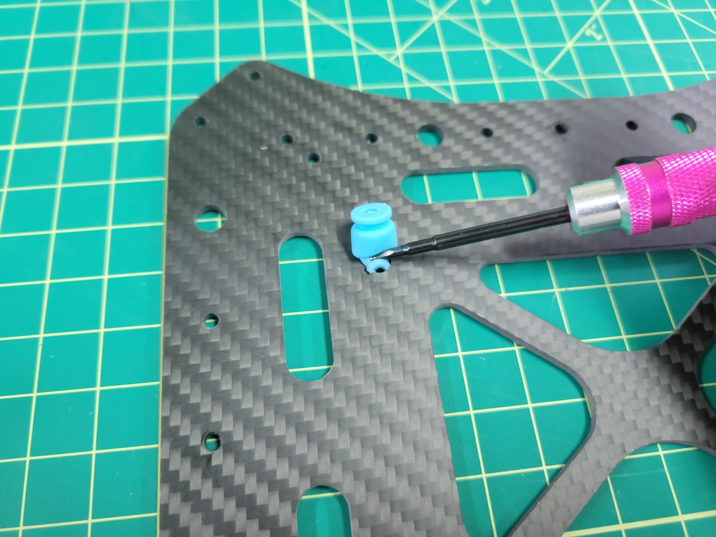
Dampener installation with 2mm hex driver
The photo below shows all four dampeners installed into the mid top plate. Proceed with installing the FC tray onto the dampeners.
FC tray ready for installation onto dampeners
You will have limited wiggle room when installing the FC tray onto the dampeners. Be patient. In a matter of no time you will become a dampener installation pro!
FC tray mounted onto mid top plate
Assembling Top and Bottom Plates
Place your mid top and bottom plates side by side as shown in the photo below.
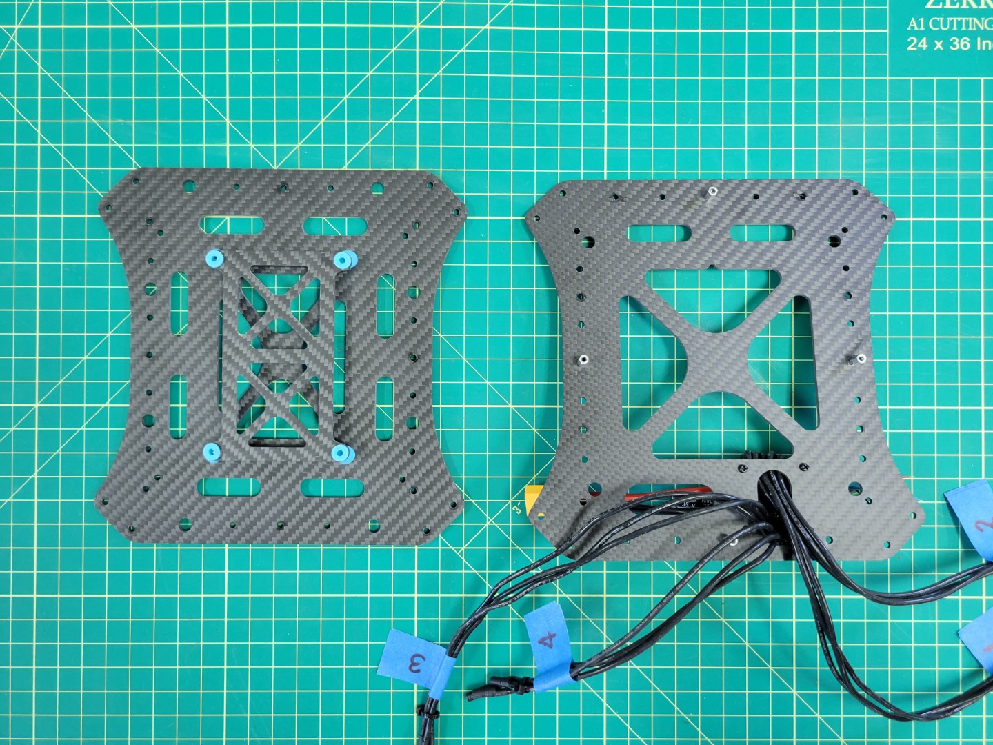
Mid top and bottom plates ready to be secured
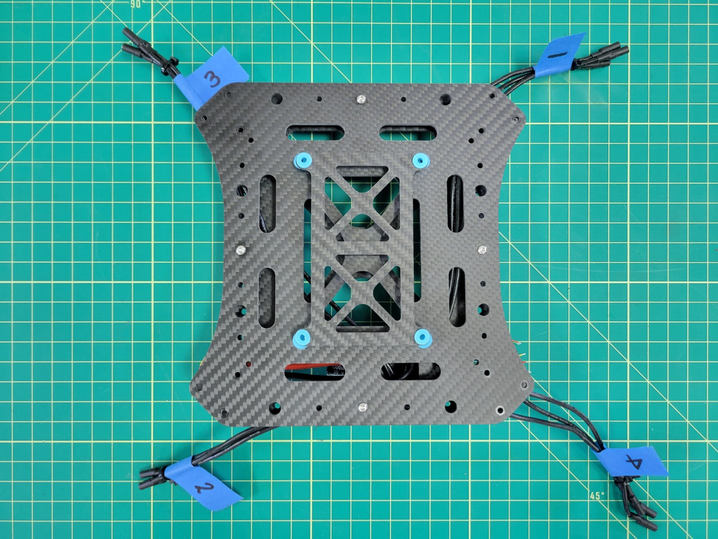
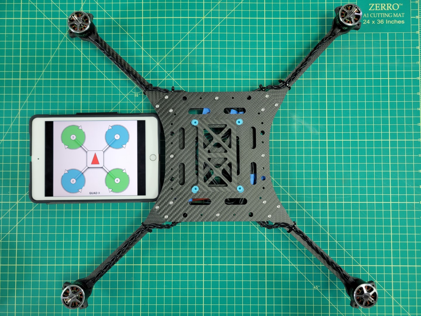
As we discussed in the previous section, motor order is incredibly important for you to have a successful flight test. Look at the motor position diagram below. Lay out each of your ESC leads in this same order.
Matching up ESCs with their motor position
Place Loctite in each of the standoffs and secure the mid top plate with four 6mm screws. Your mid plate assembly is now complete!
Completed mid plate assembly
3 - Motors and Arms
In this section we will walk through the process of mounting the drone motors to the arms of the frame
Overview
Motor position and rotation are incredibly important for any drone to fly properly. In your kit you will notice two motor boxes labeled CW (clockwise) and two CCW (counter clockwise). This represents the direction of rotation for each motor. Let’s revisit motor position and rotation in the image below:
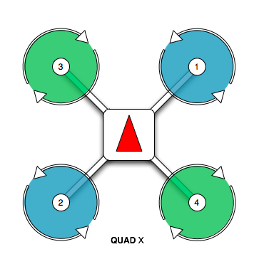
PX4 motor position and rotation
Motor positions 1 and 2 require CCW rotating motors and motor positions 3 and 4 require CW rotating motors.
You may be wondering how to determine the rotation of each motor. There are two ways to determine this. The first, and less intuitive in our opinion, is to look at the motor can. The photo below shows the motor size (2812) and kV rating (900) printed in two different formats. The kV rating for the CCW rotating motor is printed before the motor size. The kV rating for the CW rotating motor is printed after the motor size.
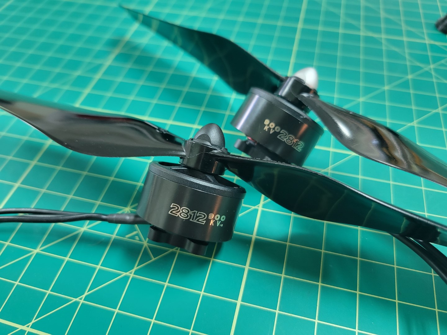
CW (black cap) and CCW (silver cap) motors
With that out of the way let’s cover a much more intutive (in our opinion) way to determine motor rotation. It requires using the propellers included in your kit. The silver capped propeller is a CCW rotating propeller and is threaded in a way that it will only screw onto the CCW motors. The black capped propeller is a CW rotating propeller. It is threaded in a way that it will only screw onto the CW rotating motors.
The photo below shows an example of installing a CW rotating propeller. Hold the propeller in place and rotate the motor in a clockwise direction. If the thread pattern is correct the propeller will screw onto the motor shaft and lock into place.
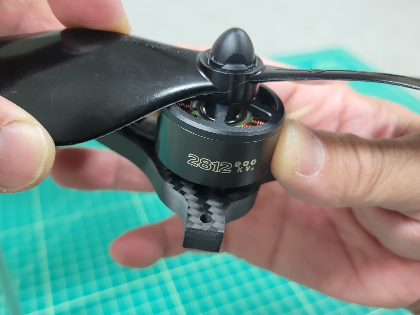
CW propeller mounting
Repeat this process for each of the four motors and then use tape to label them, just like you did with your ESC leads. You will be glad you did later!
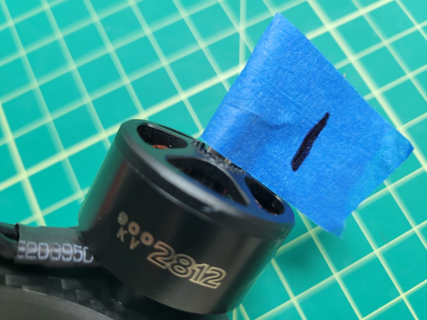
Label each of your four motors
You should have the following:
- Motor 1: CCW
- Motor 2: CCW
- Motor 3: CW
- Motor 4: CW
Attaching Motors to Arms
Inside each motor box there is a small ziploc bag of 4 x 8mm screws. In your AVR kit you will also find a ziploc bag of M3 washers.
Warning
Please be sure to use the screws provided in the small ziploc bag inside the motor box. Using longer screws from the kit can end up damaging the motor windings and ultimately prevent the motor from operating.
The photo below shows the necessary parts for mounting the motor to the frame arm. You will follow this procedure for each of the four motor/arm assemblies.
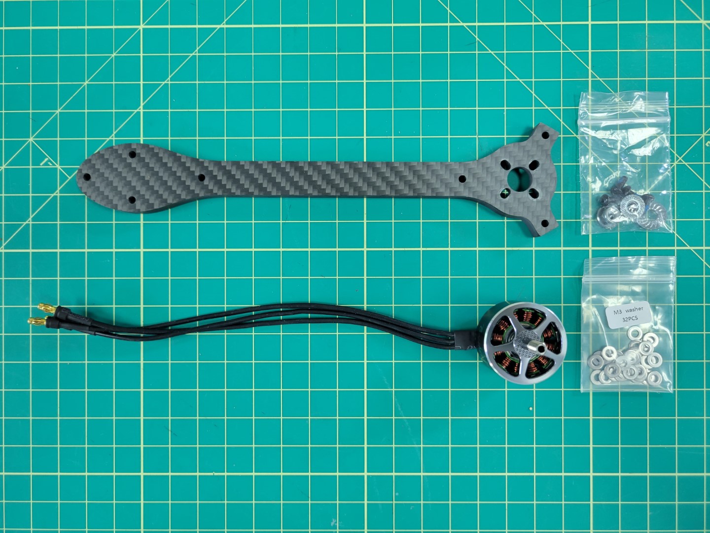
Parts necessary for mounting each motor
A 2mm hex driver is necessary to secure each of the 8mm screws into the motor.
Warning
Don’t forget to use one M3 washer with each screw. This will help reduce stress on the carbon fiber arm.
Place a small drop of blue Loctite on each screw as shown in the photo below.
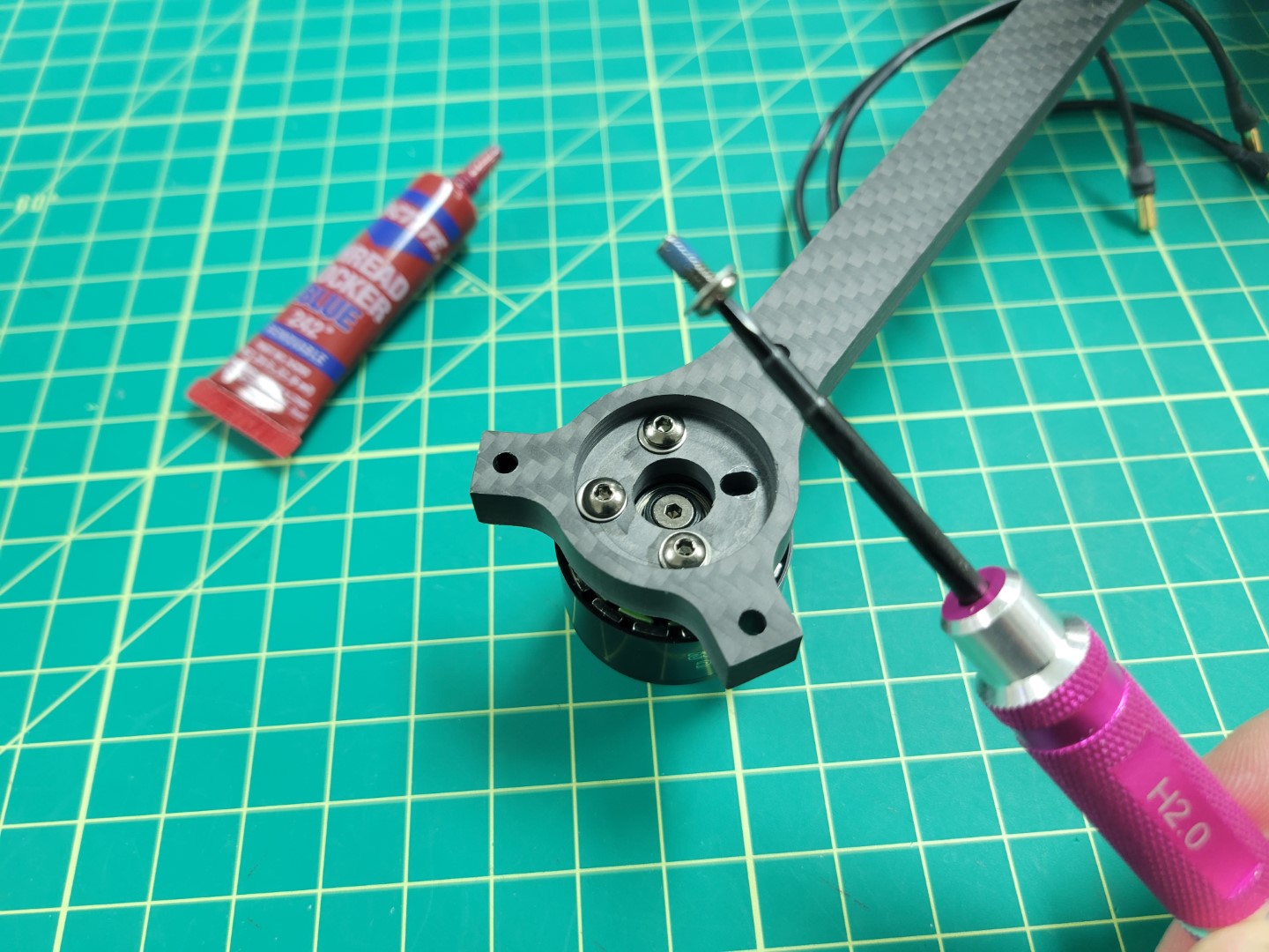
Blue Loctite on motor screw
Loctite is useful in helping secure your screws and prevents them from coming loose.
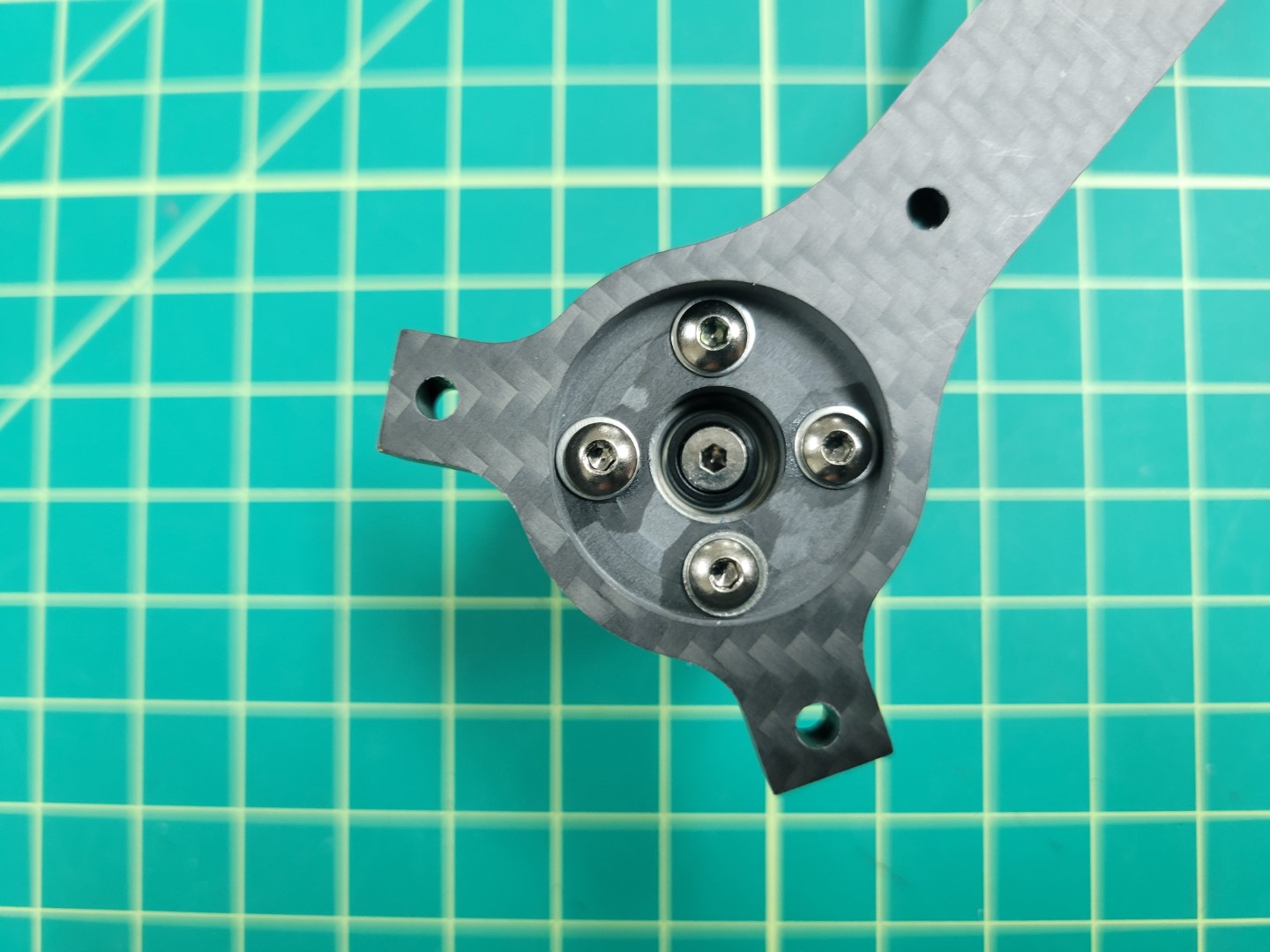
Motor mounted and secured
Repeat this process for all four of the motors.
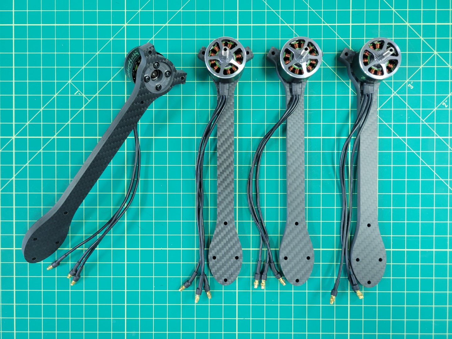
All four motor/arm assemblies complete
Attaching Arms to Midplate
Note
To proceed with this step you must 3D print four landing gear mounts. Make sure to print with 100% infill as these mounts will experience a lot of stress from the weight of the drone and hard landings.
Locate the M3 22mm screws and lock nuts in your AVR kit. These will be necessary for mounting the motor arms to the midplate and securing the 3D printed landing gear mount.
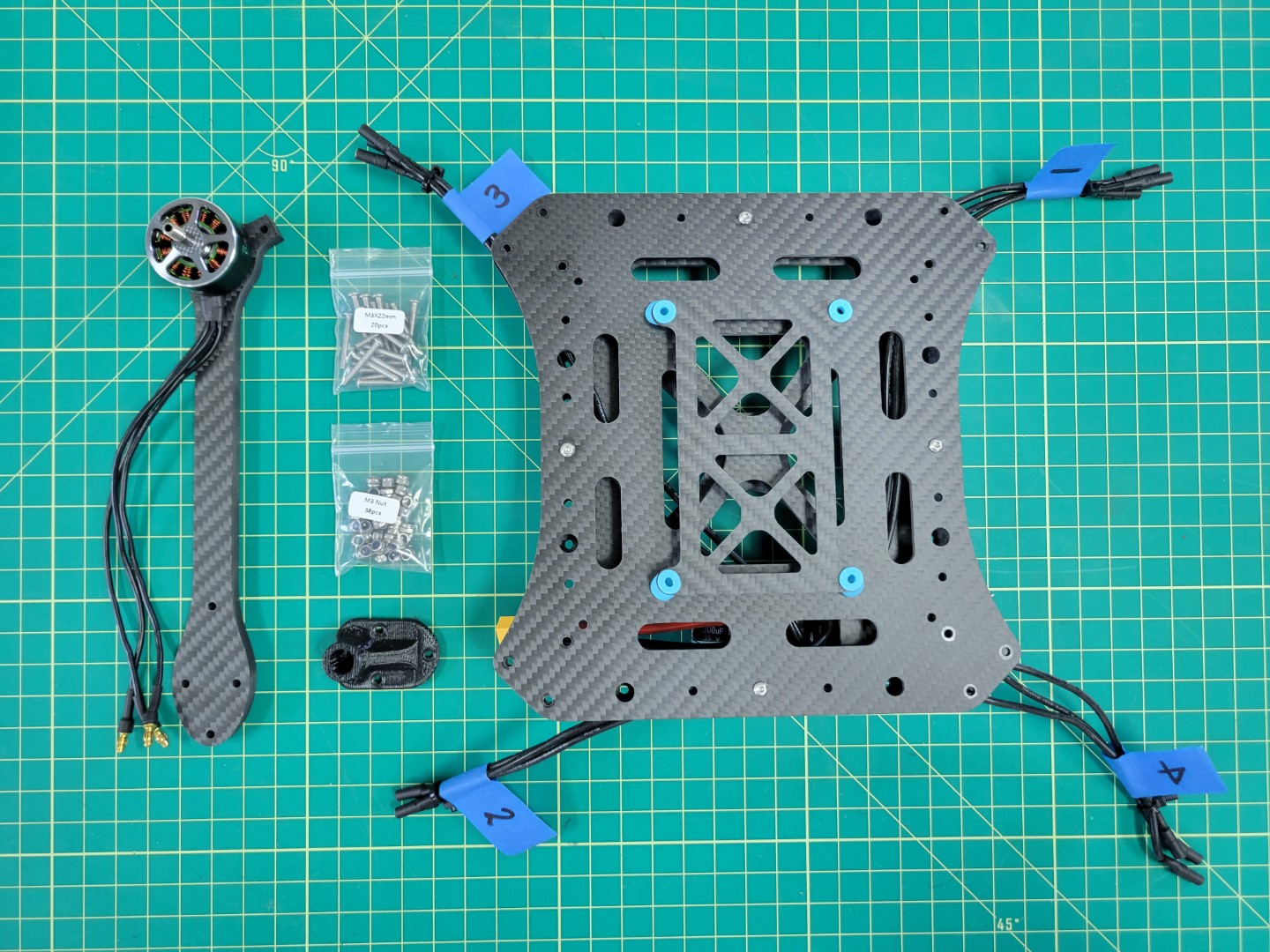
Parts for motor arm mounting
Each arm will require three 22mm screws and lock nuts. You will insert each of the screws through the top plate, arm, bottom plate, and landing gear mount. The lock nut will be secured from the bottom as shown in the photo below. A 5.5mm box driver is necessary for tightening the nut. Be sure to tighten each nut securely.
Tip
Save yourself some trouble and make sure that the motor arms are mounted in the right position. Make sure that the labeled ESC leads match with the motor labels. Refer back to the PX4 motor image above if necessary.
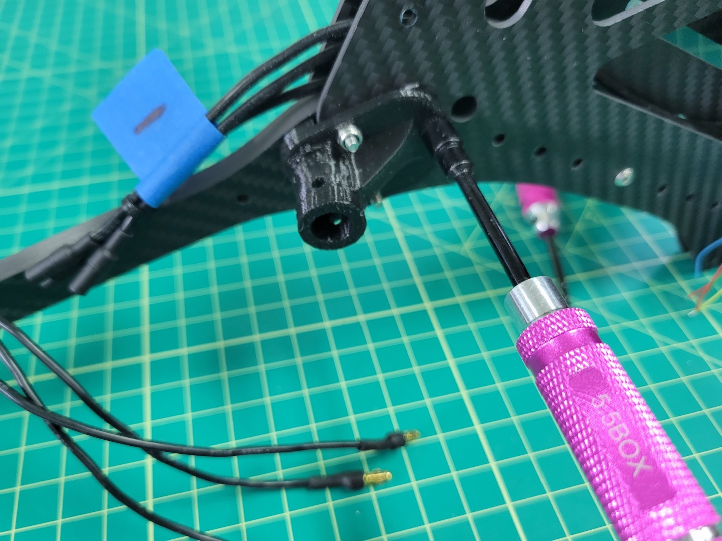
Securing lock nuts with 5.5mm driver
Repeat the installation process for each motor arm.
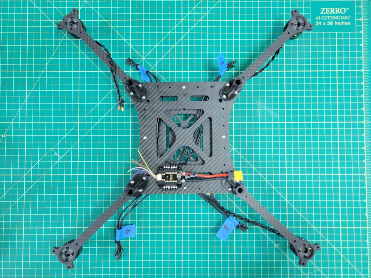
All four motor arms secured
Flip your AVR drone over and connect each of the motor leads to the corresponding ESC leads.
Motors and ESCs ready to be connected
Be sure to make a good connection between the male leads of the motor to the female leads of the ESC. You should not see any brass between each of the connections. This is important so that nothing comes loose or causes a potential short.
Motors and ESCs all wired up
Feed any excess cable slack between the top and bottom plates. You can use zip ties to clean up your cabling as shown in the photo below.
Zip ties keep you build nice and tidy
Motor position and rotation is an important part of any drone build. The photo below is a gentle reminder. It won’t be long before you have this photo memorized!
Motor position and rotation
4 - FC to ESC Wiring
We will walk through creating the FC and ESC cable
FC Wiring
Note
This section of the build requires some additional tools not included in your AVR kit such as a soldering iron, heat shrink tubing, wire strippers, and a hobby knife.
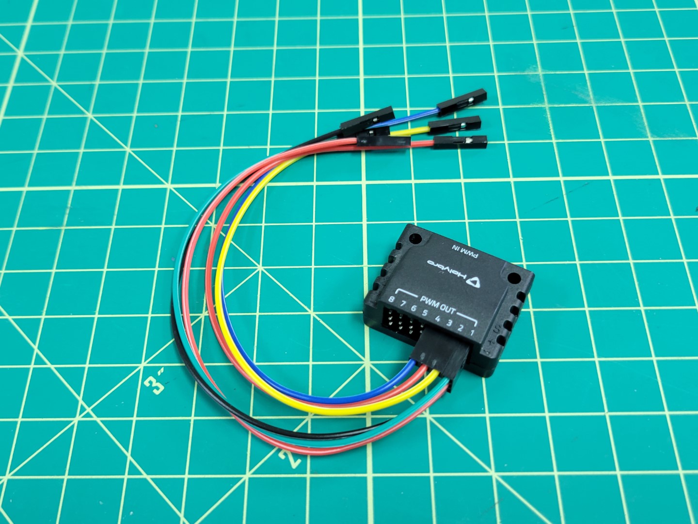
You may have noticed that the ESC has a connector with several flying leads coming out of it. These leads are what we will be connecting to the FC. The FC will send PWM (Pulse Width Modulation) signals to each of the motors to keep the AVR drone hovering in the air.
Remove the small white cable adapter from the ESC and gather the necessary parts for this phase of the build as seen in the photo below.
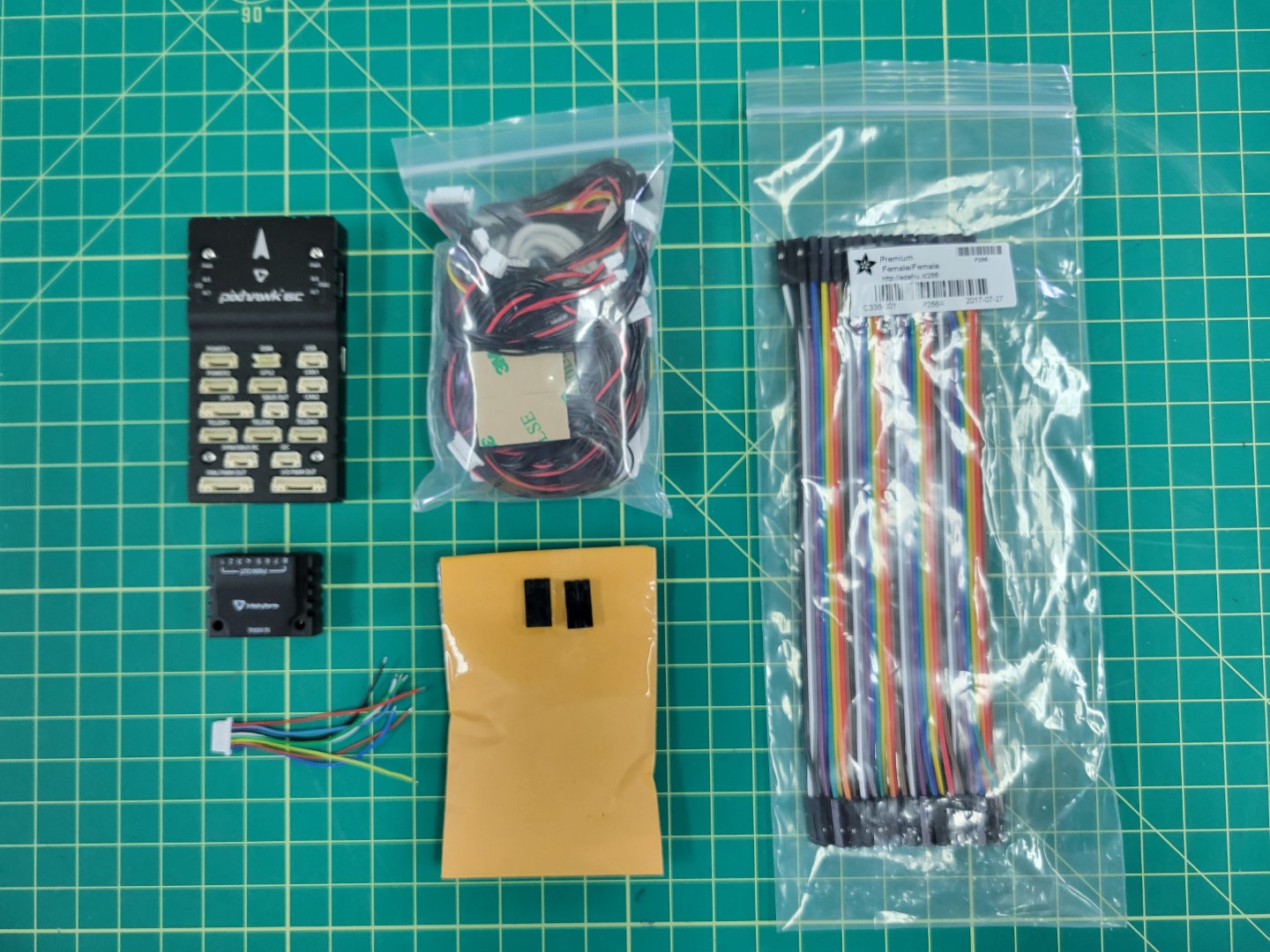
Parts for wiring FC to ESC
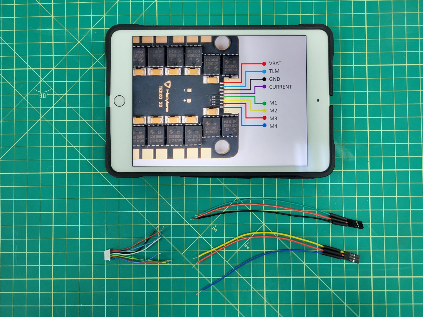
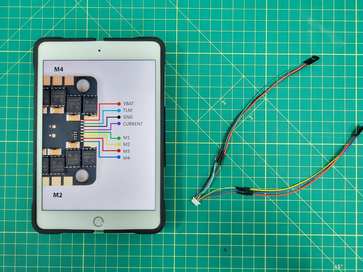
The image below shows the pinout for the ESC connector. We will be focused on wiring each of the motor leads (M1-M4) as well as VBAT and GND to the PWM module of the FC. We will not be using TLM or CURRENT.
Warning
Each of the leads has a small amount of wire exposed. Go ahead and clip off the exposed wire of the TLM and CURRENT leads.
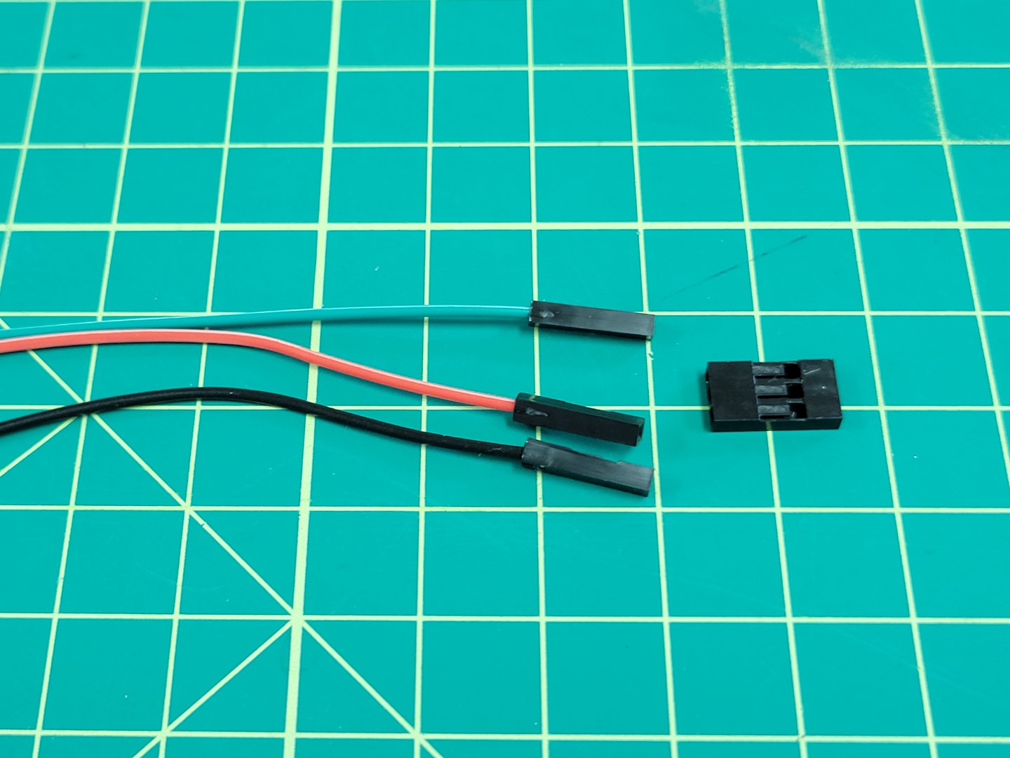
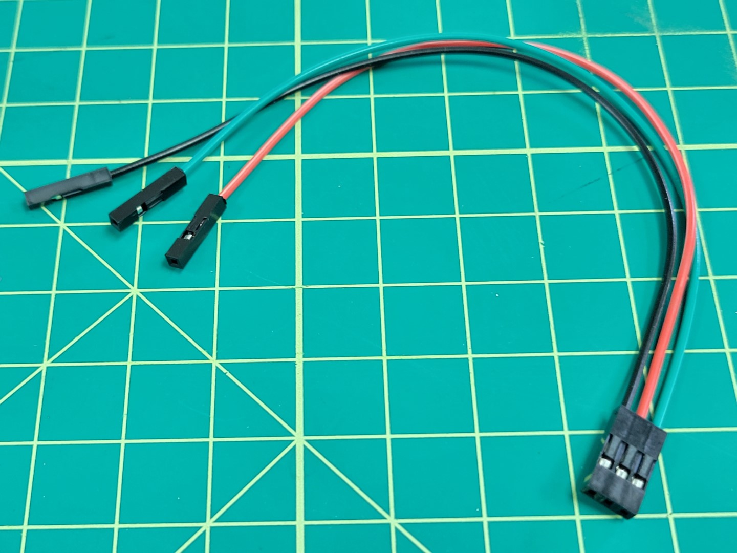
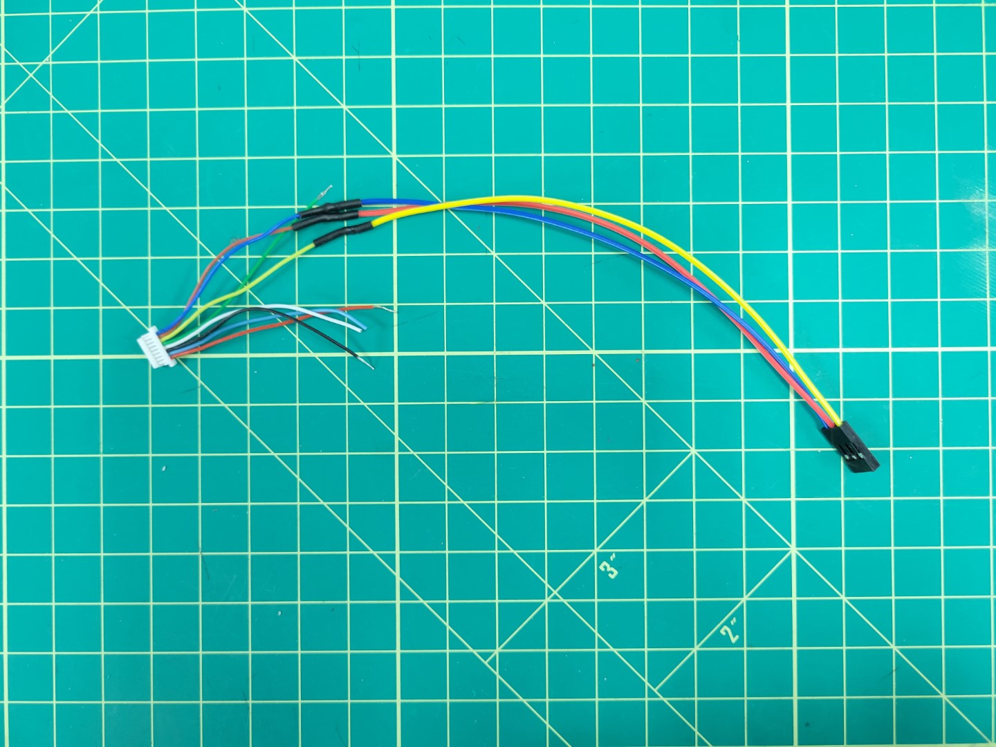
Pull out four jumper cables from your AVR kit and to keep things simple make sure they mach up with each of the motor wire colors. They will be green (M1), yellow (M2), red (M3), and blue (M4) as seen in the image below.
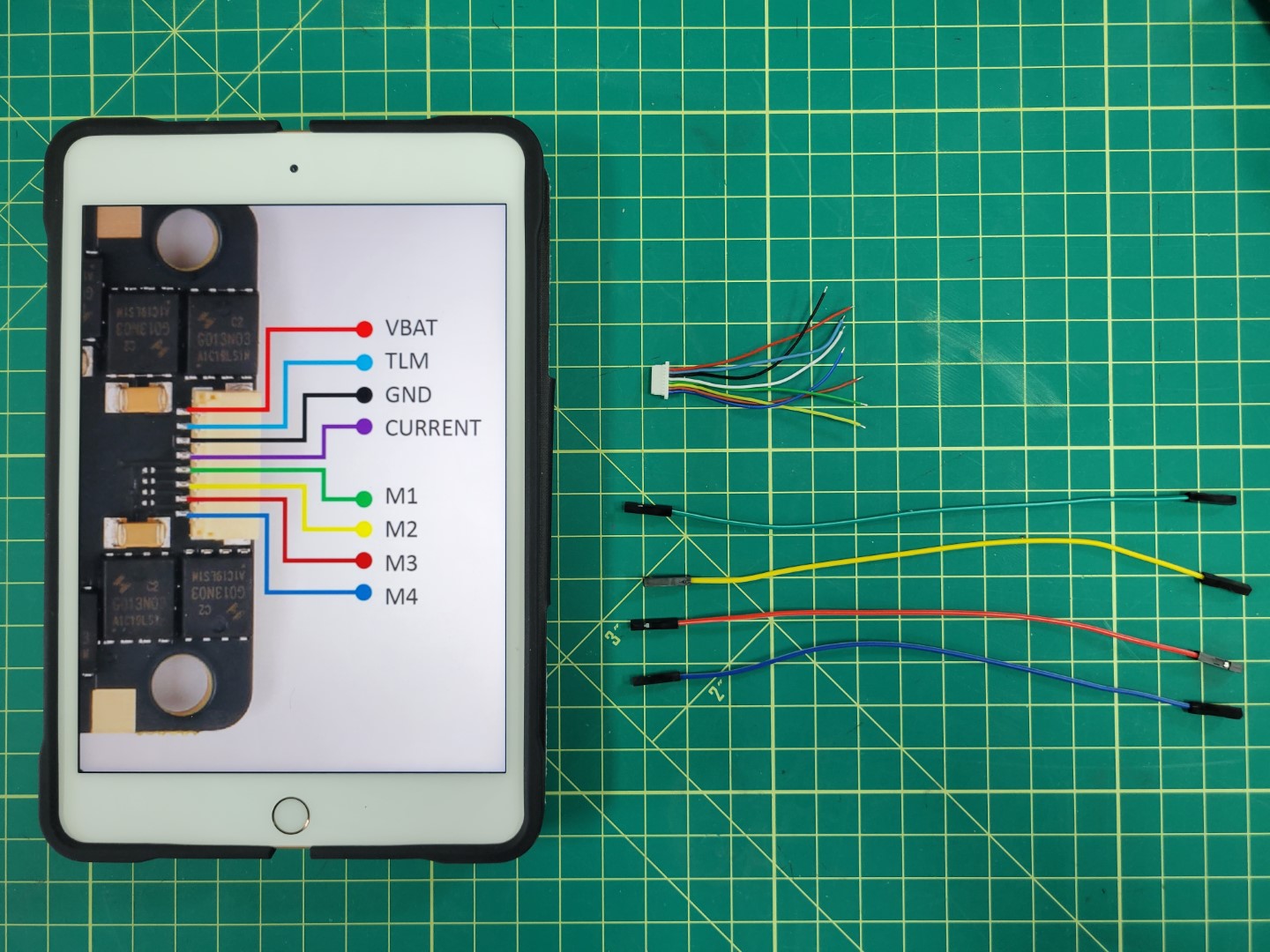
Laying out wires for soldering
Remove the plastic female connector from one end of each jumper cable. This is easy to do once you understand how the connector works. There is a small tab that you can pry up and then slide the cable out. A small flat head screwdriver or tweezers area great tools to assist with this step.
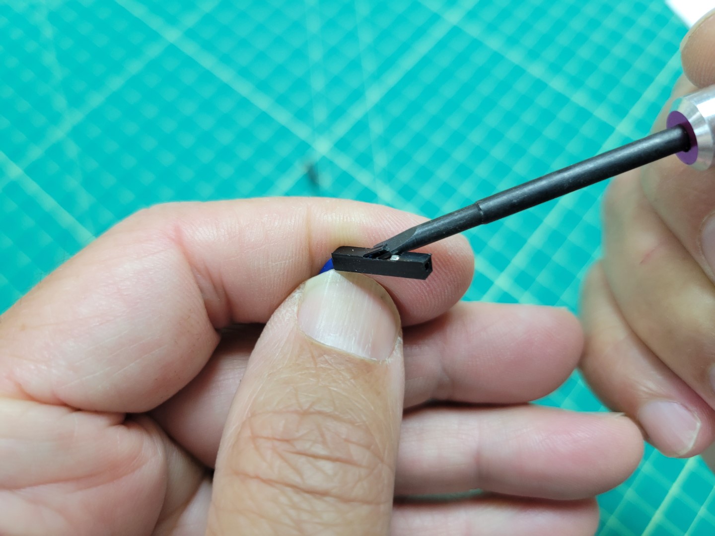
Plastic connector with tab lifted up
Slide the wire all the way out and get rid of the plastic connector.
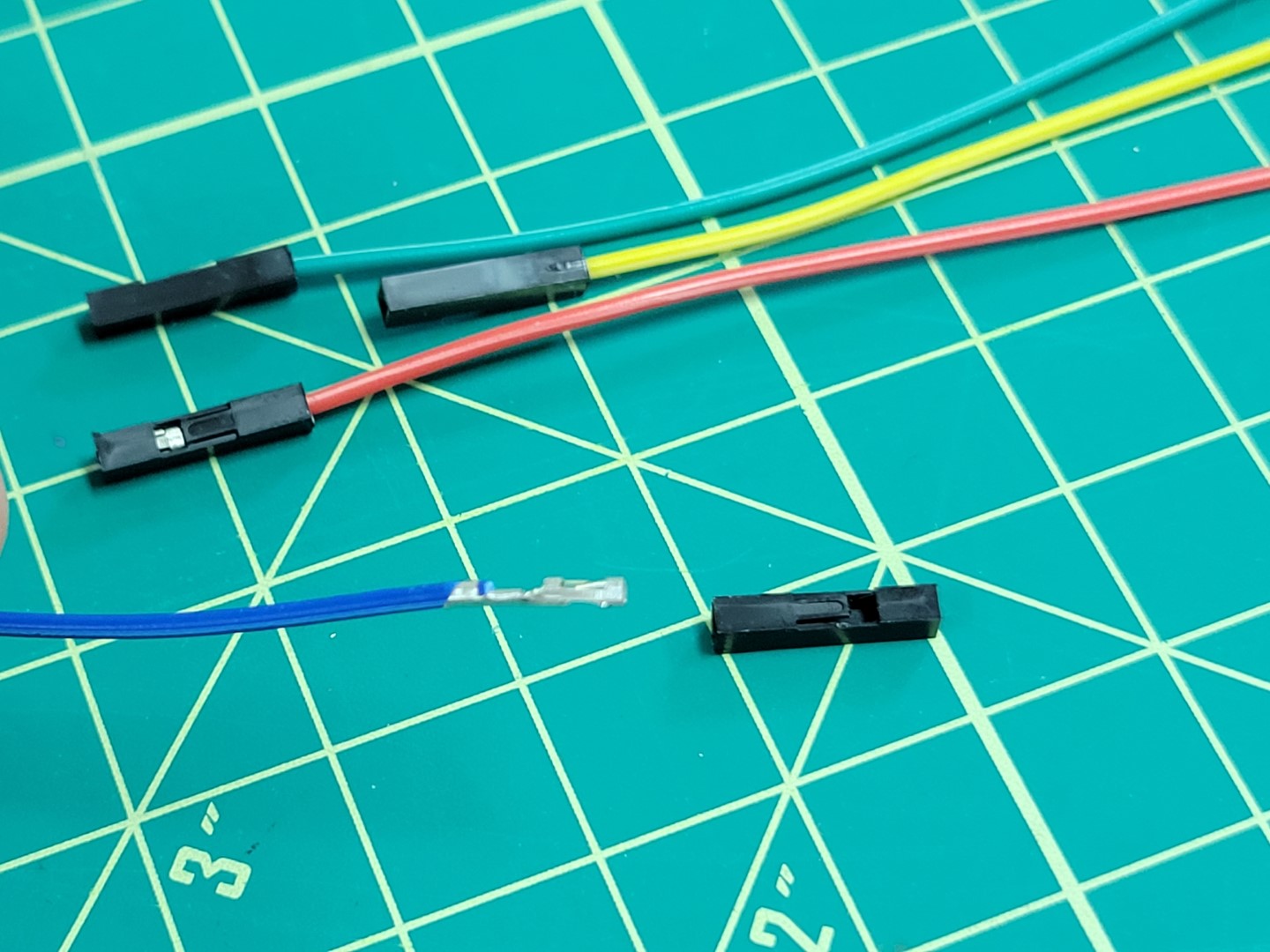
Wire removed from plastic connector
Slide the wire into the servo connector housing as shown in the photo below. Servo connectors can be found in a small envelope of miscellaneous parts in your kit. Refer back to the first photo in this section to see it.
Note
Make sure that you listen for a click sound when sliding the wire into the servo connetor. Pay attention to the orientation of the wire in the photo below. When the wire is secure you can lightly pull on it and it will not come out.
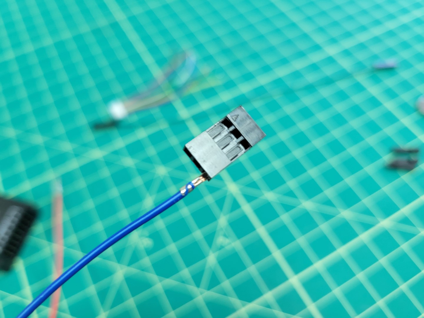
Sliding wire into servo connector
The blue wire is now secured into the connector and represents motor #4 (M4).
M4 wire securely in place
We will repeat this step for M2 (yellow wire) and M3 (red wire).
Warning
Motor order is incredibly important! Pay close attention to make sure your wire colors correspond with the correct motors.
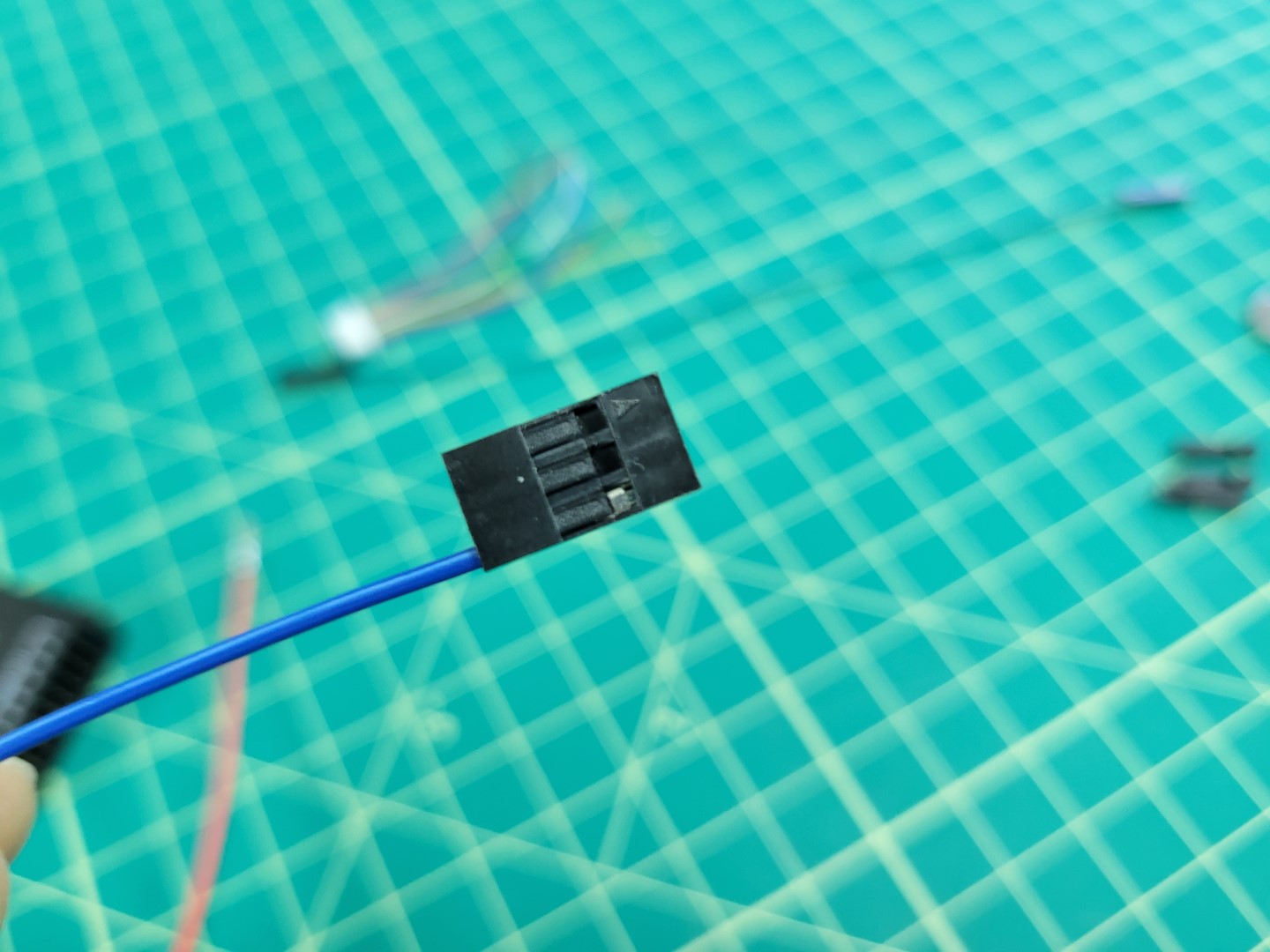
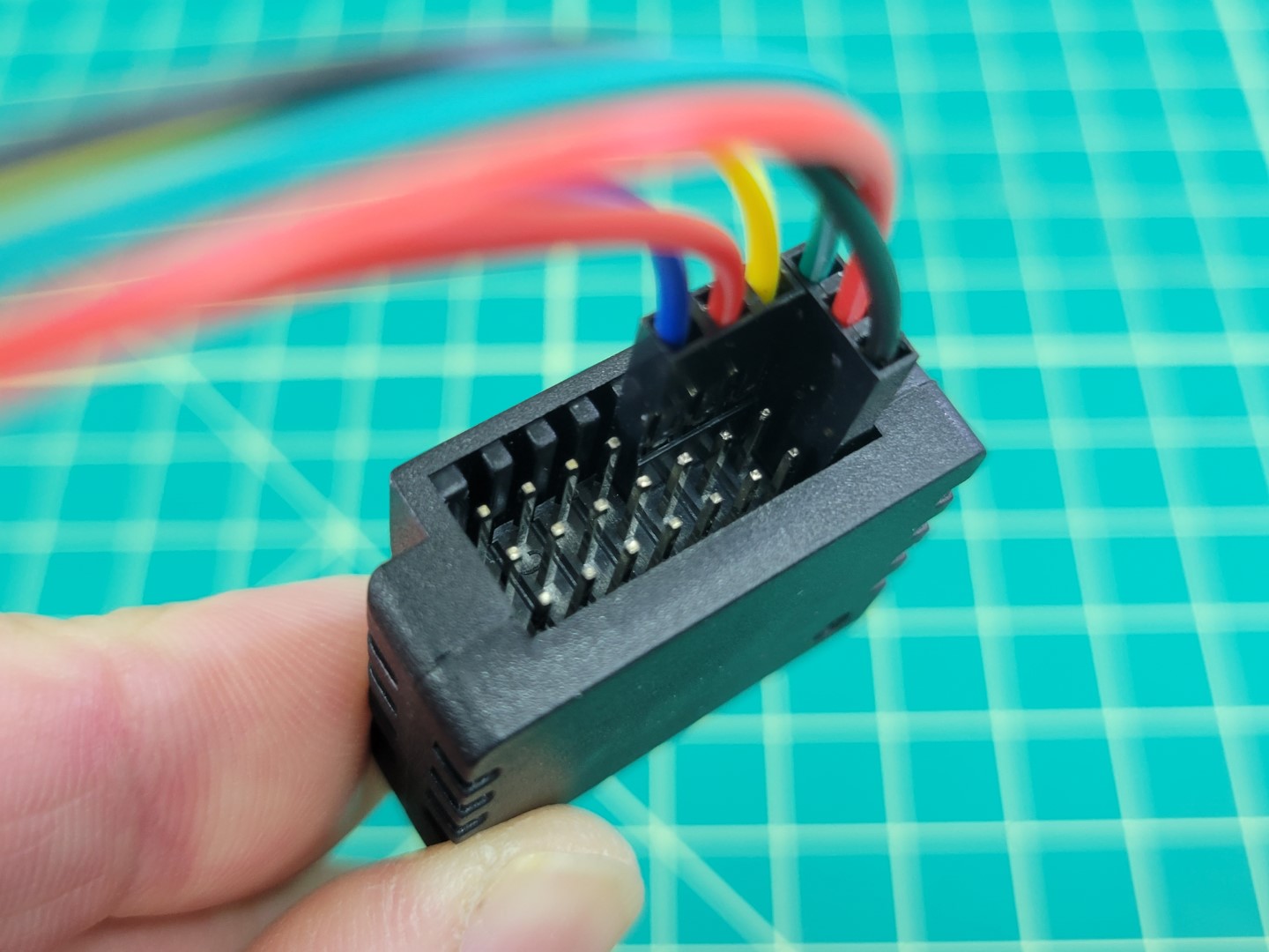
The photo below shows how the cable will be attached to the PWM module from the Pixhawk. You will notice that the connector is plugged in horizontally across the top row of pins 2, 3, and 4. Pixhawk can support up to 8 motors (an octocopter) and each number represents a specific motor.
Tip
If you look closely at the PWM module you will see S, +, - labeled on the right side. This means the top row of pins are SIGNAL pins, the middle are POWER pins, and the bottom are GROUND pins.
M2, M3, and M4 connector
Let’s repeat the same process for M1 (green), VBAT (red), and GND (black). You will remove each of the plastic female connectors and secure the wires into the servo connector.
M1, VBAT, and GND wires
Once again, pay attention to the ordering of your wires. Your second cable should look identical to the one below.
M1, VBAT, and GND in servo connector
Make sure your cables are plugged into the PWM module as shown below.
PWM module wired up
Here is a close up of the connections. This represents the FC side of the wiring. Now we will proceed with the ESC side.
PWM module close up
ESC Wiring
Go ahead and unplug your cables from the PWM module. Let’s take one last look at the ESC side connections before we solder.
Use wire cutters to cut off the plastic female connectors from the other end of the colored leads. Proceed with stripping off about 1/2" of the wire insulation.
Remove about 1/2" of insulation from the ESC leads. You will notice that the ESC leads already have some wire exposed.
Tip
The ESC leads are very thin. We have found it easiest to pinch with your fingernails and pull the insulation away. Use caution as you do not a lot of spare wire on the ESC side!
Match up the wire color on the FC side with the same color on the ESC side. Twist the wires together using the “Twisted Helix” method described in the video below.
Warning
Don’t forget to add heat shrink tubing before twisting your wires together! The heat shrink will be necessary to keep the connections from shorting after you solder.
The photo below shows the blue M4 wire from the ESC connected to the M4 wire of the FC. The wires are secured using the “Twisted Helix” method.
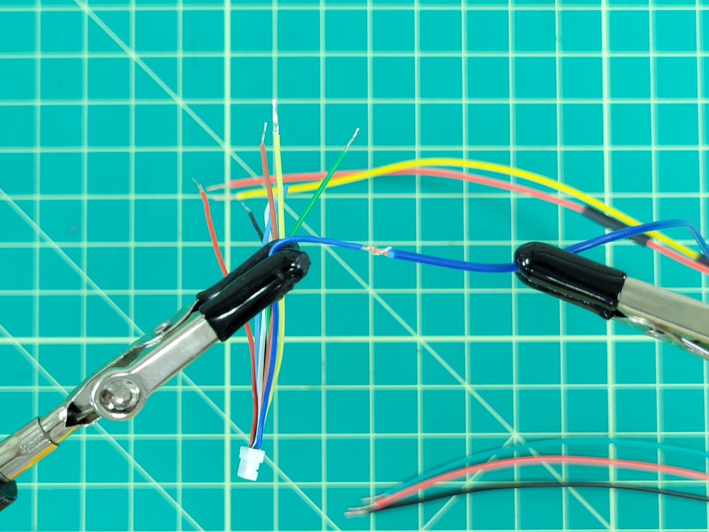
Wires twisted and ready for soldering
Tip
A helping hands device makes the soldering process 100x easier. Whatever method you use take care not to pierce the insulation of the wires. You can see in the photo below our alligator clips are covered with rubber shields.
Place solder all around the joint to strengthen the connection.
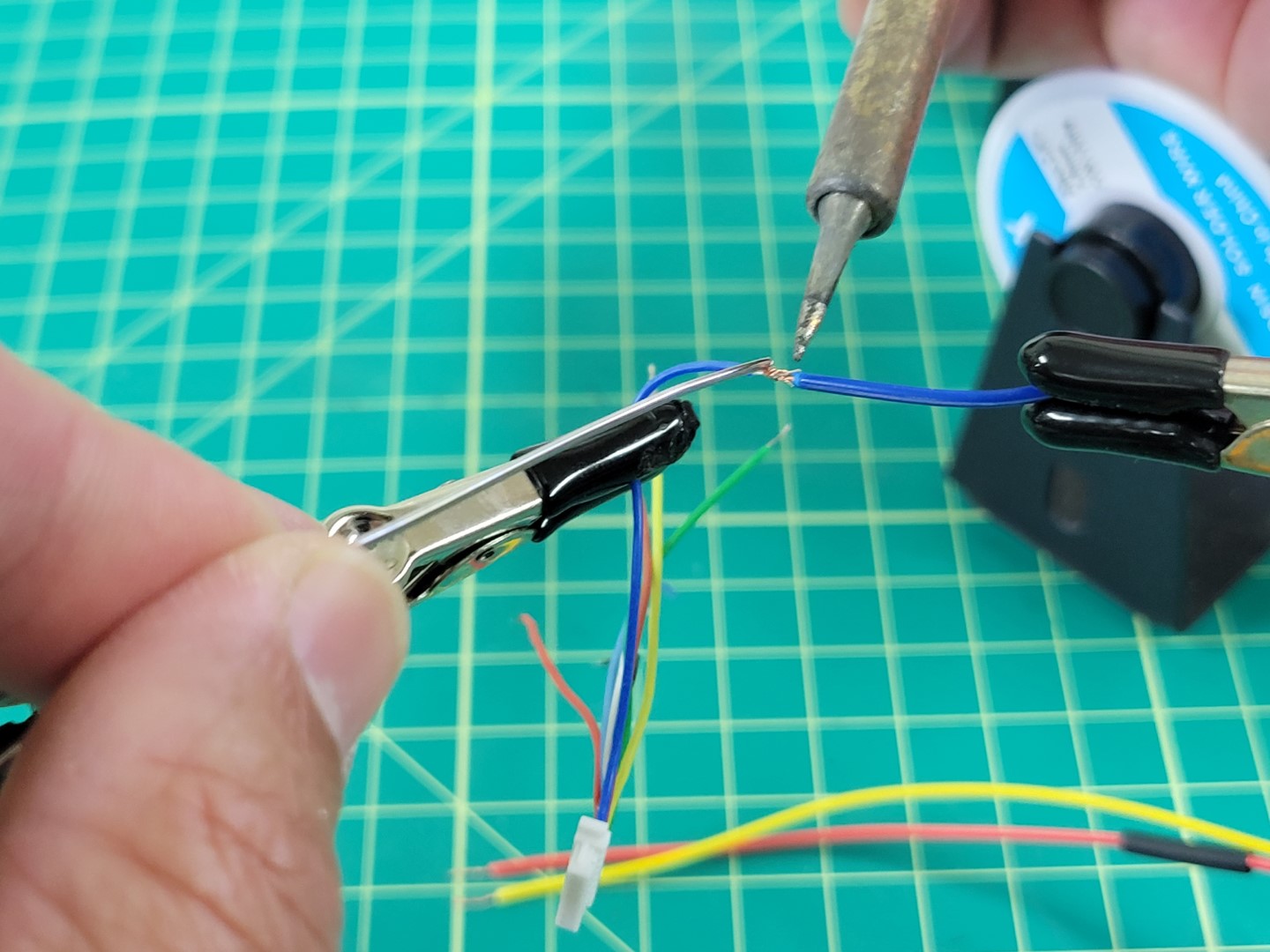
Soldering the ESC and FC M4 wires together
A little solder will go a long way. Don’t overdo it as you will need to slide the heat shrink over the joint next.
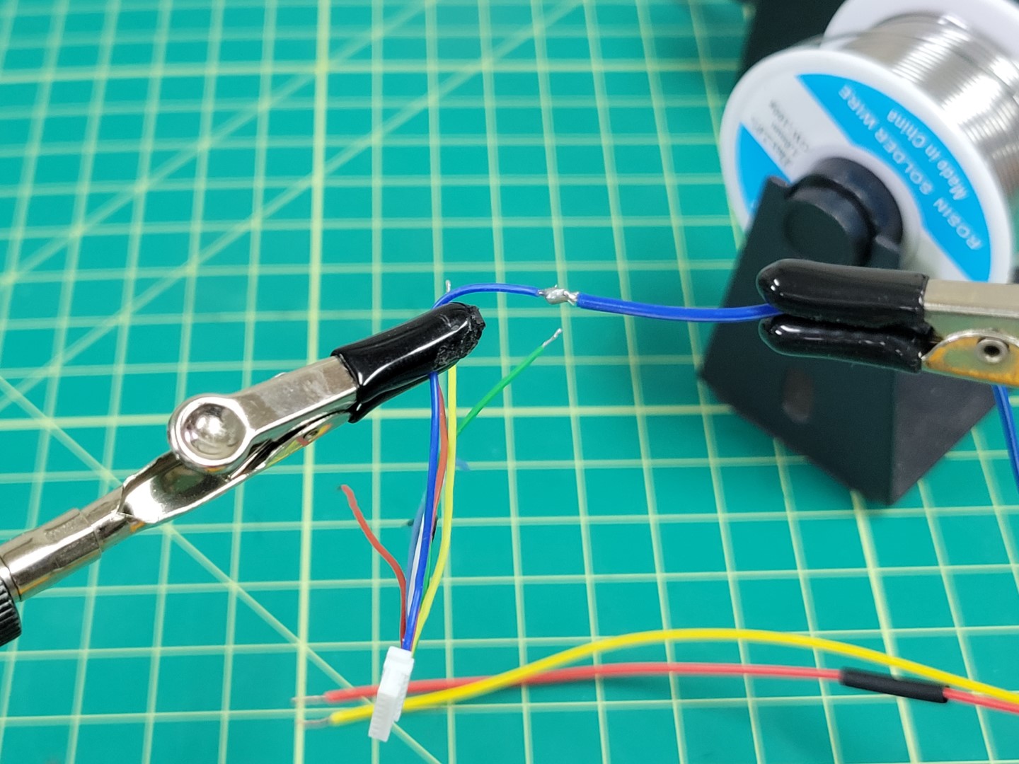
M4 wires soldered together
Slide the heat shrink over the connection and apply heat to it using a heat gun or a lighter.
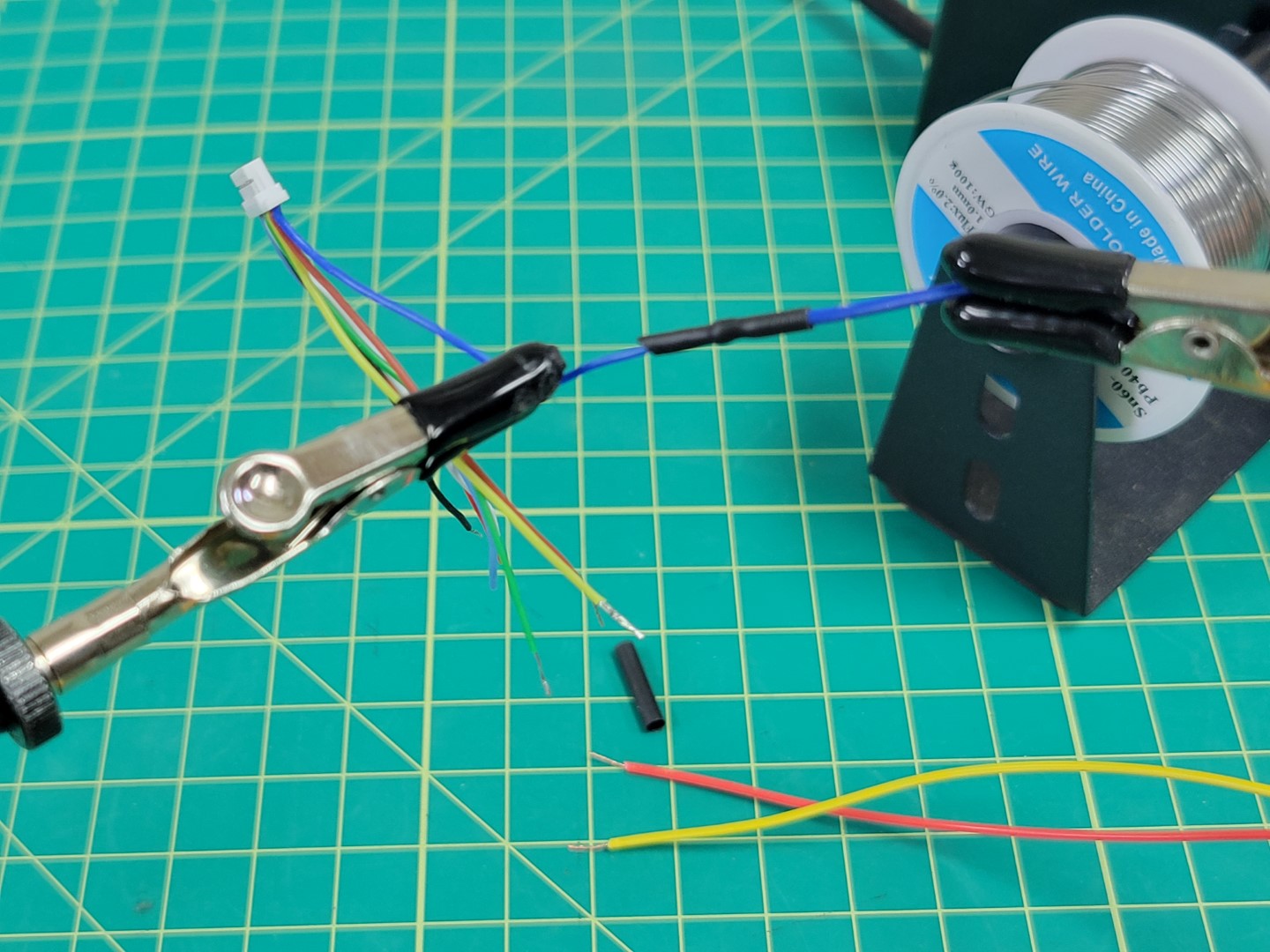
Heat shrink applied to M4 wire
Repeat this process for the M2 (yellow) and M3 (red) wires.
Warning
Red wire was used for both M3 and VBAT. Make sure not to get these wires mixed up!
M2, M3, and M4 wires soldered
Repeat the soldering process for M1 (green), VBAT (red), and GND (black). Your new cable should look like the photo below.
Warning
One last reminder to make sure you clip the exposed leads from the TLM and CURRENT wires.
All wires soldered
Feel free to apply heat shrink over all your wires to keep things clean. If you don’t have heat shrink you can use electrical tape.
Plug your connectors into the Pixhawk PWM module as shown in the photo below.
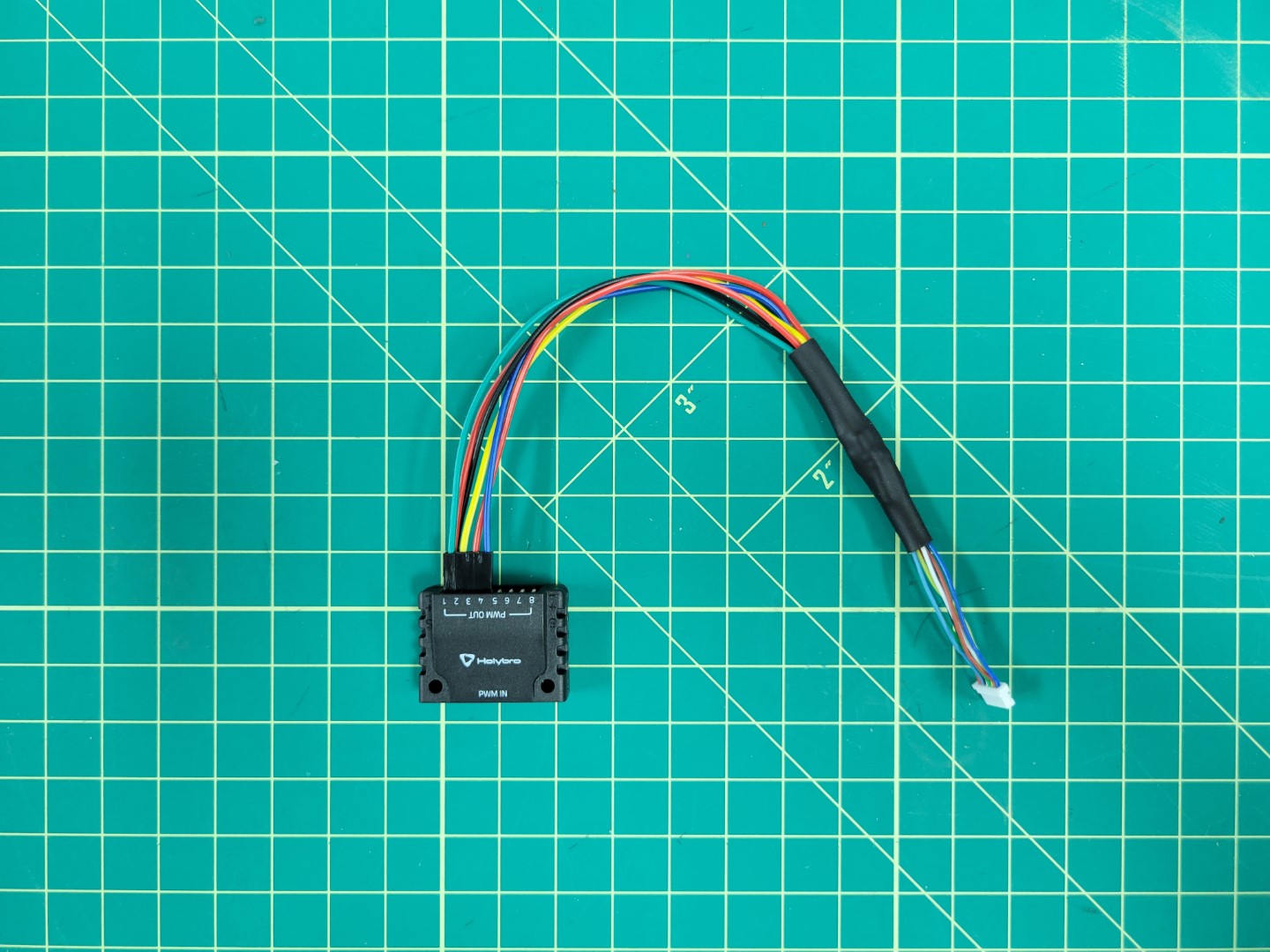
The finished FC to ESC cable
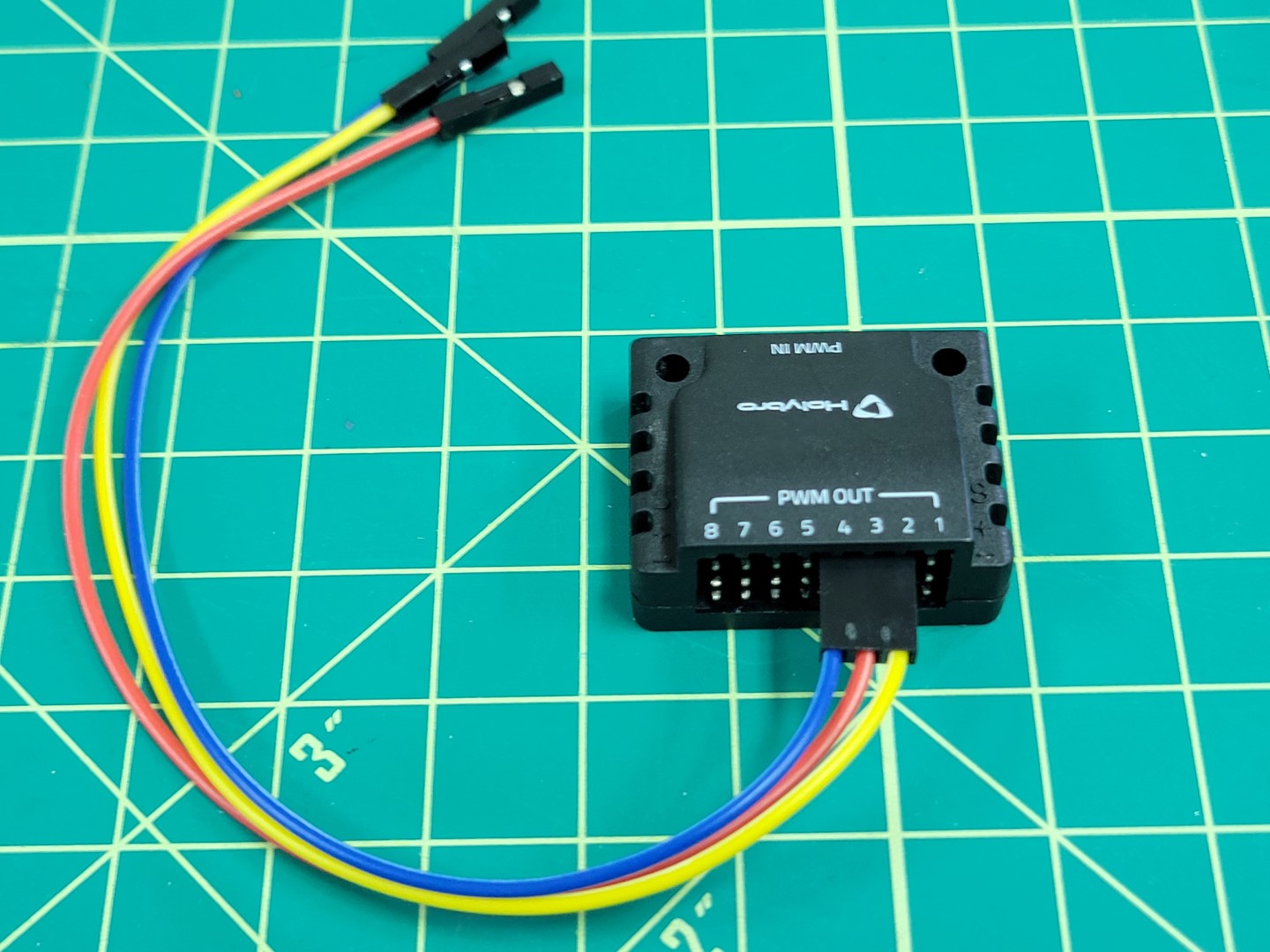
In the bag of cables that came with your Pixhawk FC look for the 10 pin connector that attaches to the Pixhawk’s I/O PWM OUT port and the PWM IN port on the PWM module.
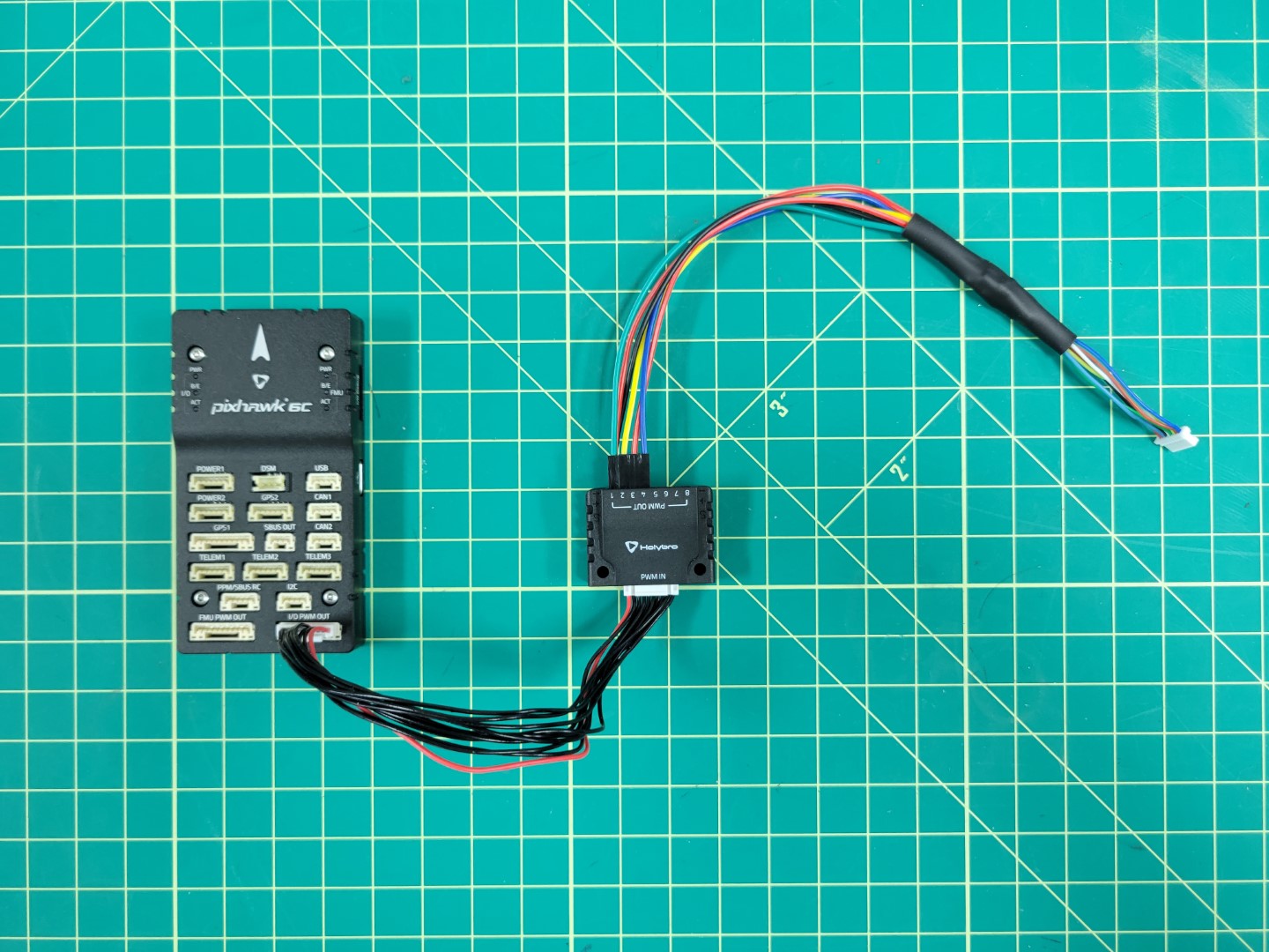
Connecting PWM module to Pixhawk
5 - FC Mounting
We will walk through mounting the FC and connecting the RX and power modules
FC Mounting
Locate the sheet of 3M double-sided adhesive pads and cut one out. Then cut it in half.
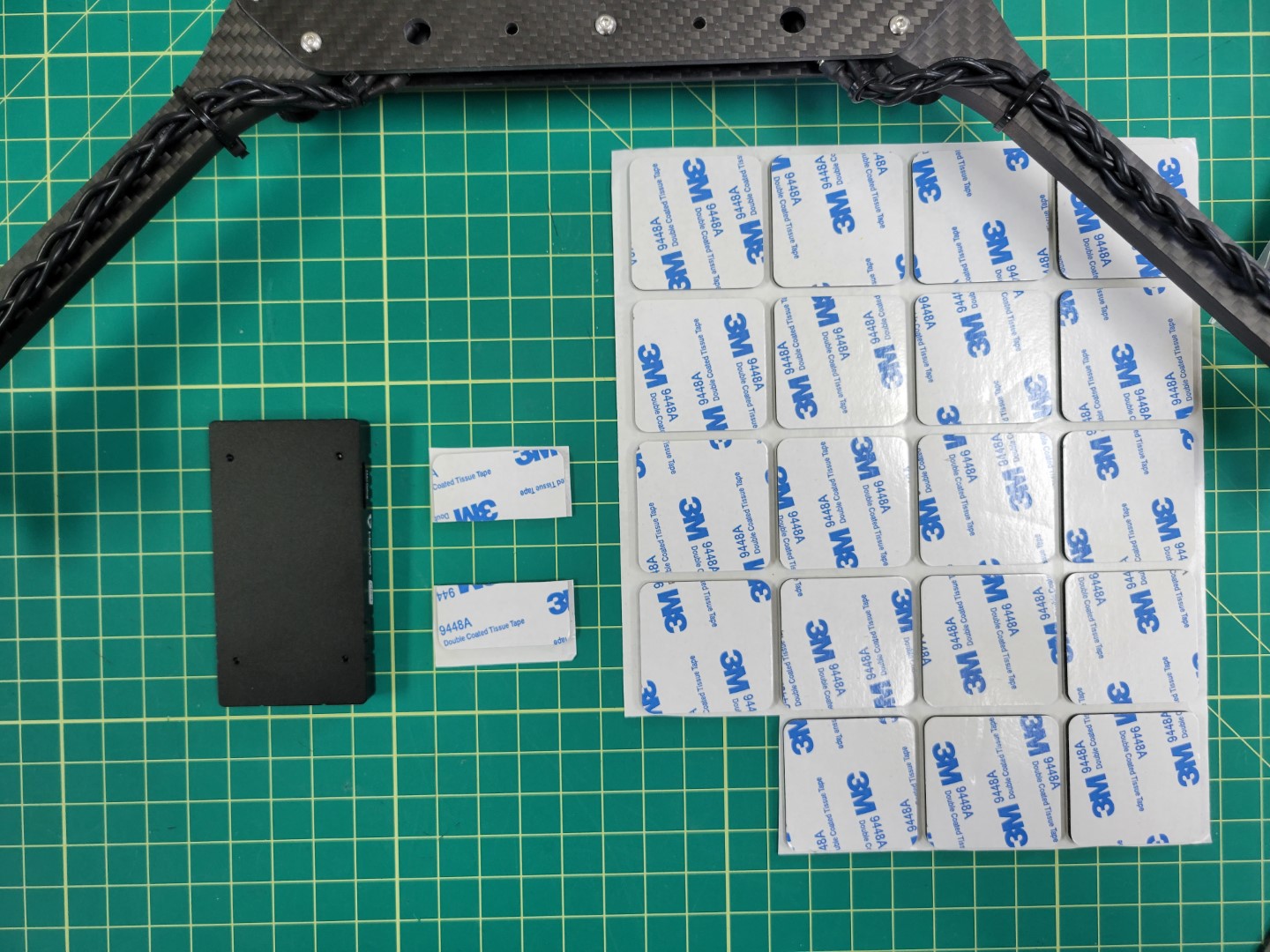
3M double-sided pads
Place each half at the front and back of the Pixhawk FC.
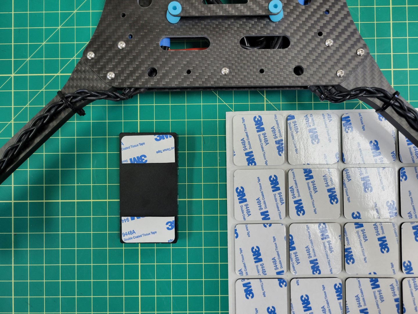
Pad applied to Pixhawk FC
Center the FC over the top tray and press it firmly into place.
Warning
Double check that the arrow on your FC is pointed forward towards motors M1 and M3.
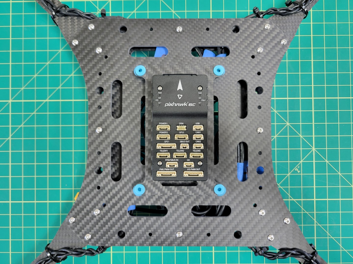
Pixhawk mounted to top tray
PWM Module Mounting
Let’s connect the cable we previously created to the ESC beneath the frame. You can see in the photo below that we’ve zip tied it to the mid bottom plate to keep it in place. Feed the other end of the cable to the top of the frame.
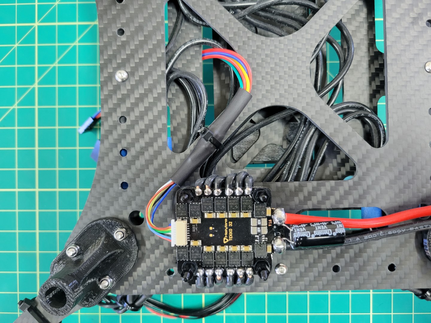
ESC/PWM cable secured to frame
Cut out a small piece of 3M tape and secure your PWM module to the frame as shown in the photo below. Wire up your connections.
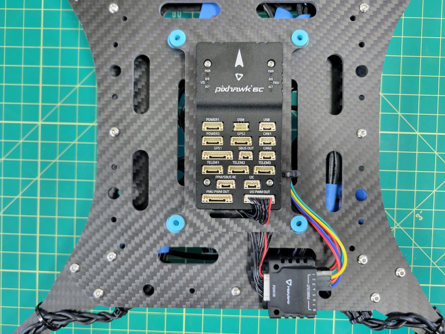
PWM Module mounted and wired
RX Mounting
The radio receiver (RX) will be mounted next. You can find the RX in the FlySky FS-i6S box. The cable to connect the RX will be in the bag of cables inside the Pixhawk box.
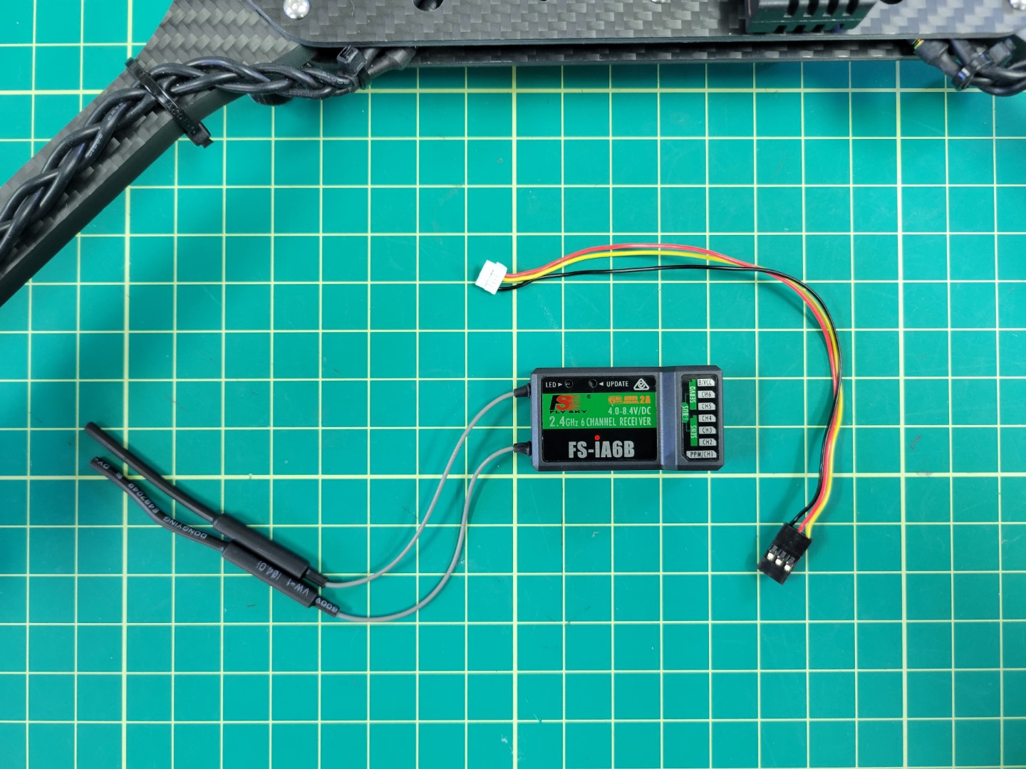
RX module and cable
Mount the RX using 3M tape as shown below. Attach the cable to the PPM/SBUS RC port of the Pixhawk and the other end of the cable to the I-BUS SERVO port of the RX.
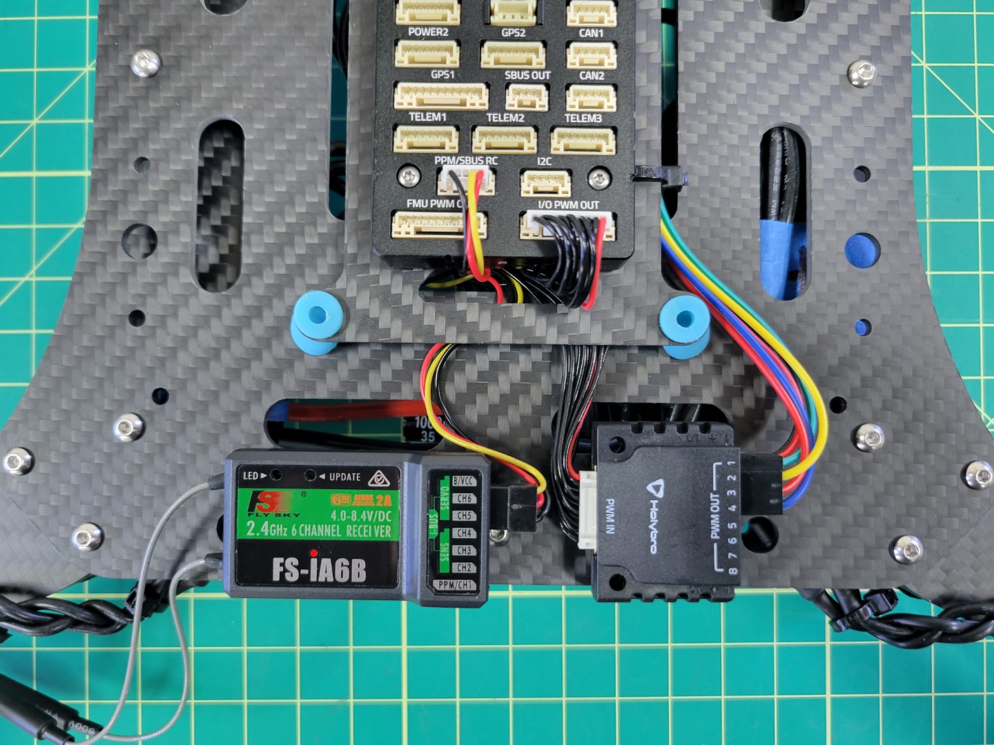
FS-iA6B RX Connected to Pixhawk
Power Module
The Pixhawk Power Module steps down the battery voltage for use by the FC. It also provides voltage and current monitoring. This monitoring will be critical for the AVR competition and will help teams understand the power profile of their drone. Both the power module and cable can be found in the Pixhawk box.
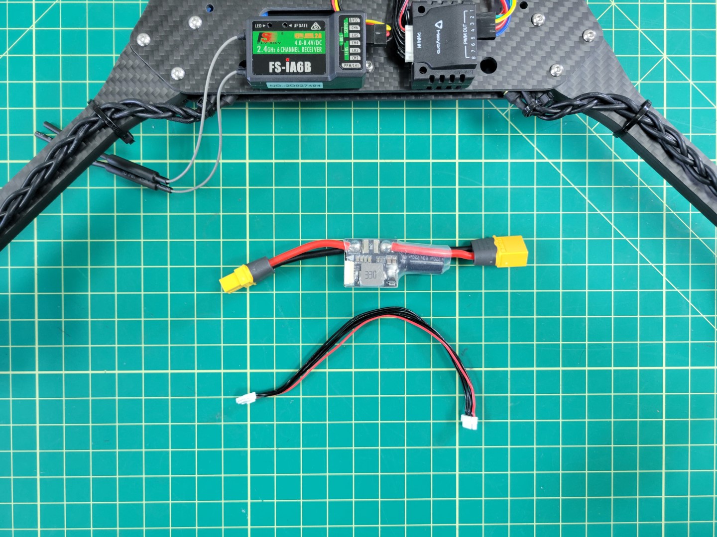
Pixhawk power module and cable
Plug the female XT60 connector of the power module into the male XT60 of the ESC. Then plug the FC cable into the port of the power module as shown in the photo below.
Connecting FC power module to ESC
Feed the power cable from the module to the top of the frame and plug it into the POWER1 port of the Pixhawk.
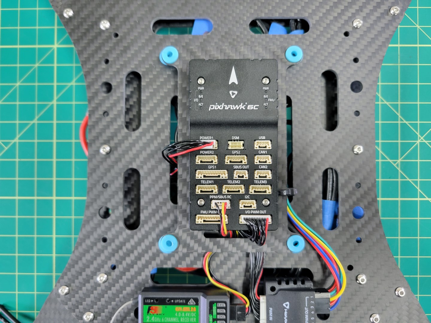
Pixhawk power connection
6 - Bottom Accessory Plate
This page walks through mounting the battery tray and attaching the accessory plate to the AVR frame
Battery Tray Assembly
Note
To proceed with this step you must 3D print the battery tray. An infill of 15% should be sufficient.
The parts necessary to mount the battery tray to the accessory plate are 10mm M3 screws, lock nuts, and washers.
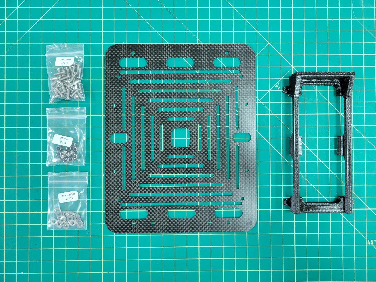
Bottom accessory plate and battery tray
Insert the screws and washers from beneath the plate coming up through the battery tray. Secure each corner with a lock nut as shown in the photo below.
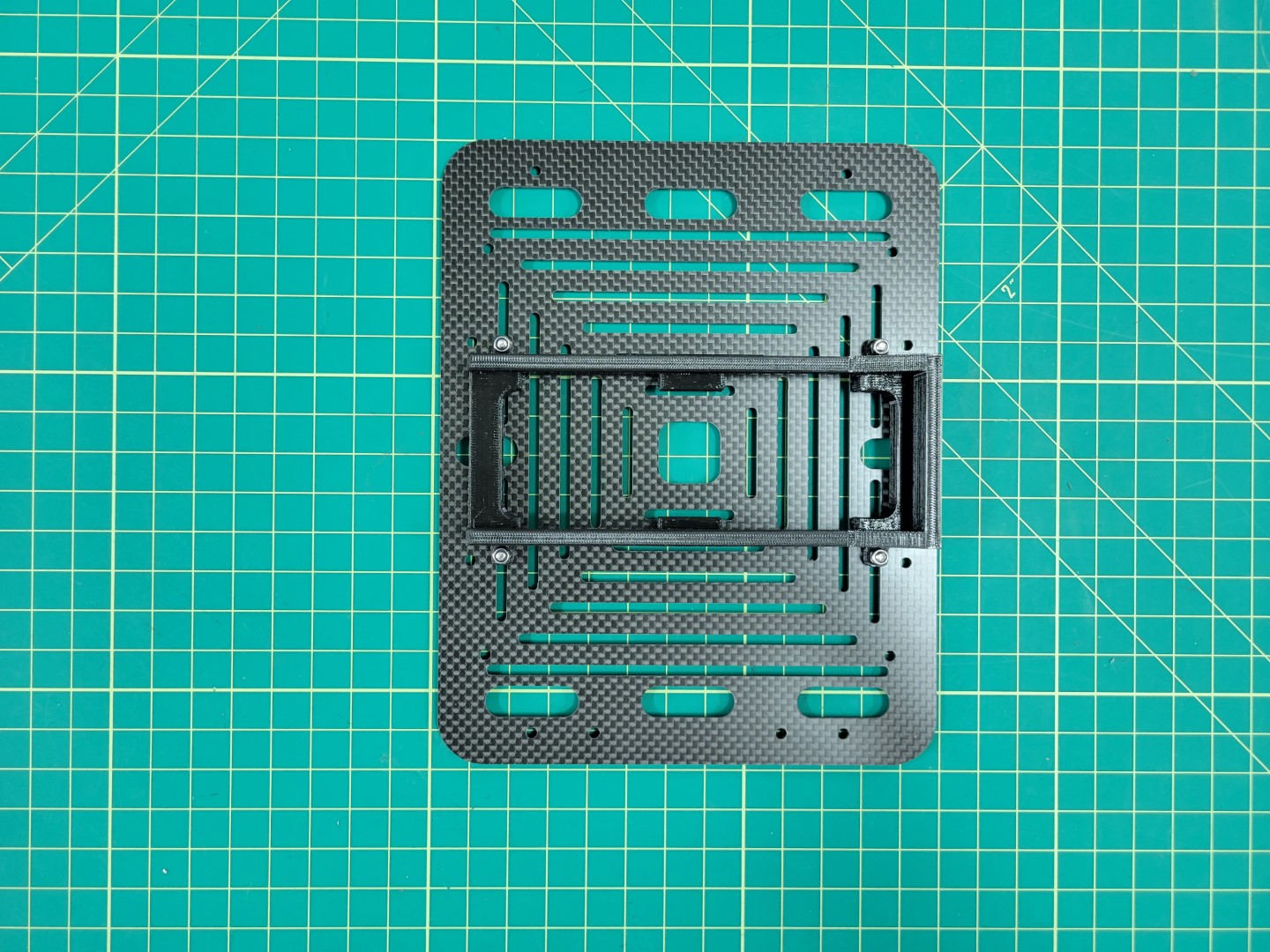
Battery try mounted to accessory plate
Attaching Accessory Plate
Let’s attach the bottom accessory plate to the mid plate assembly of the AVR frame. You will need the 60mm standoffs and 10mm M3 screws that come with your kit.
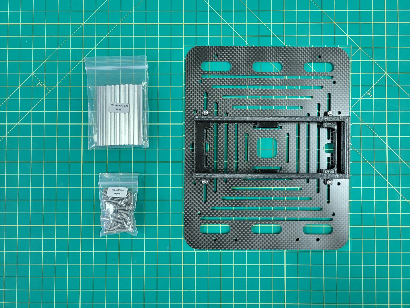
Standoffs and screws for accessory plate mounting
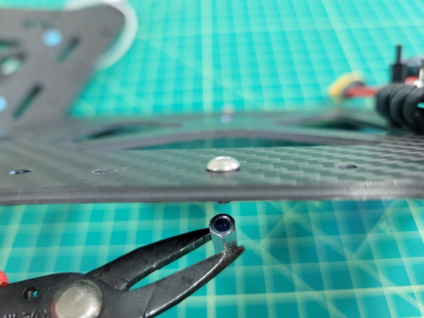
From the top of the midplate assembly locate the eight larger access holes. Place a 10mm screw through each access hole into the mid bottom plate. A pair of needle nose pliers are very helpful for this step.
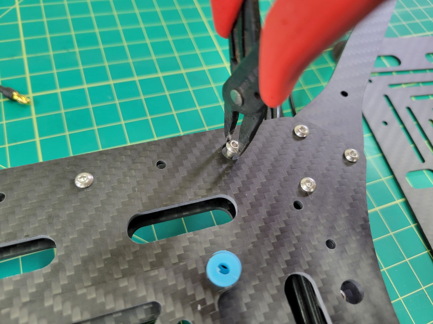
Access hole for 10mm screw
Place a small drop of Loctite into the standoff and screw into place using a 2.0mm hex driver.
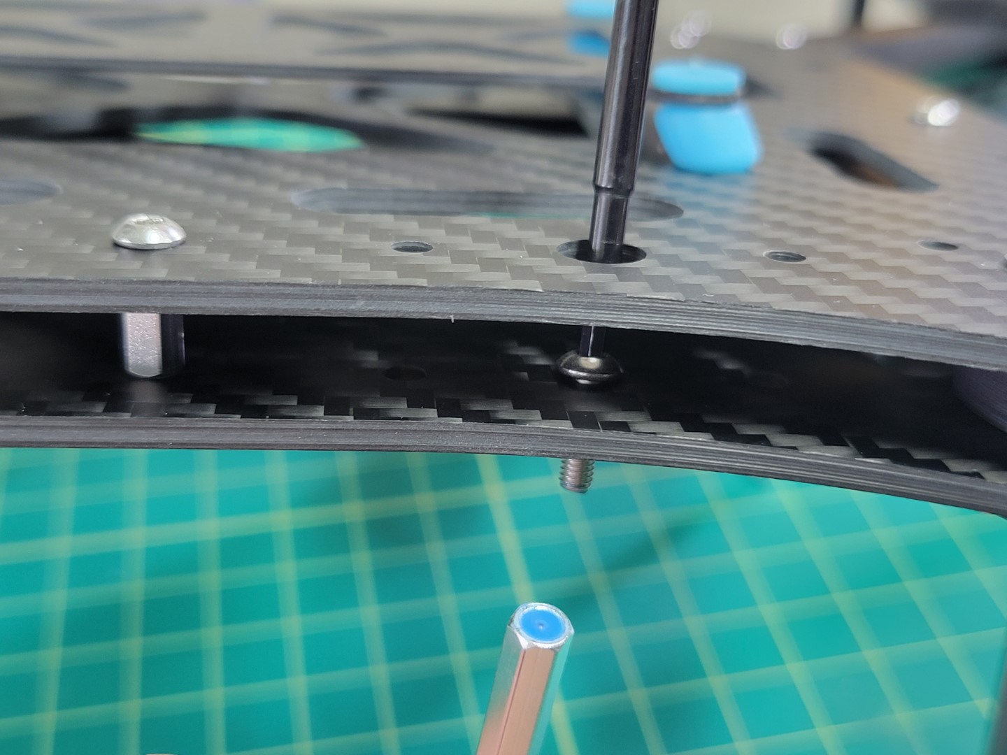
Loctite applied to 60mm standoff
Repeat this process for all eight standoffs. Flip your AVR frame over so that the standoffs are facing up. Place a drop of loctite into each of them.

Standoffs with Loctitue
Place the bottom accessory plate onto the standoffs and secure with 10mm screws.
Warning
Make sure that the two holes denoted by the yellow circles below face the front of the drone. These holes will be essential when mounting the ZED Mini camera during advanced drone assembly.
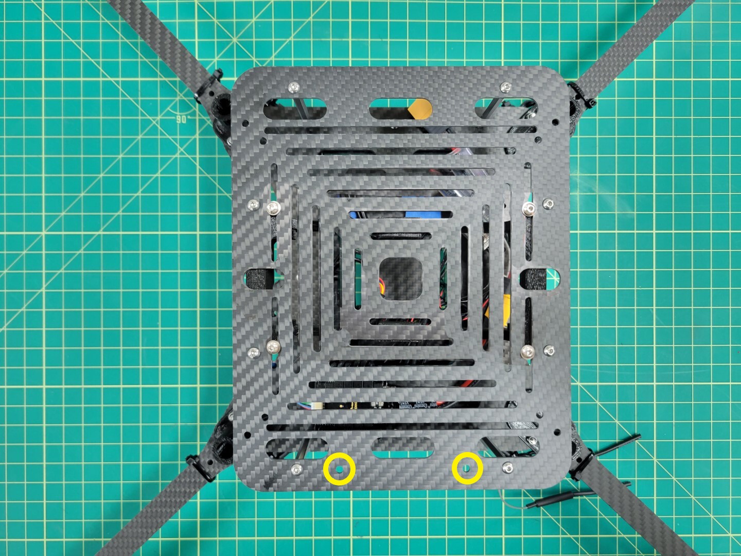
Bottom accessory plate secured and ZED Mini holes facing front of frame
7 - Landing Gear
This page will guide you through the process of drilling and installing your landing gear
Landing Gear Drilling and Mounting
Note
To proceed with this step you must have 3D printed the landing gear brace and foot (x4).
Your AVR kit ships with 4 x 9" aluminum rods that are used for landing gear. As you get further into the advanced part of the build you can shorten these rods with a metal hacksaw. Customization is largely dependent on what accessories you have mounted to your drone.
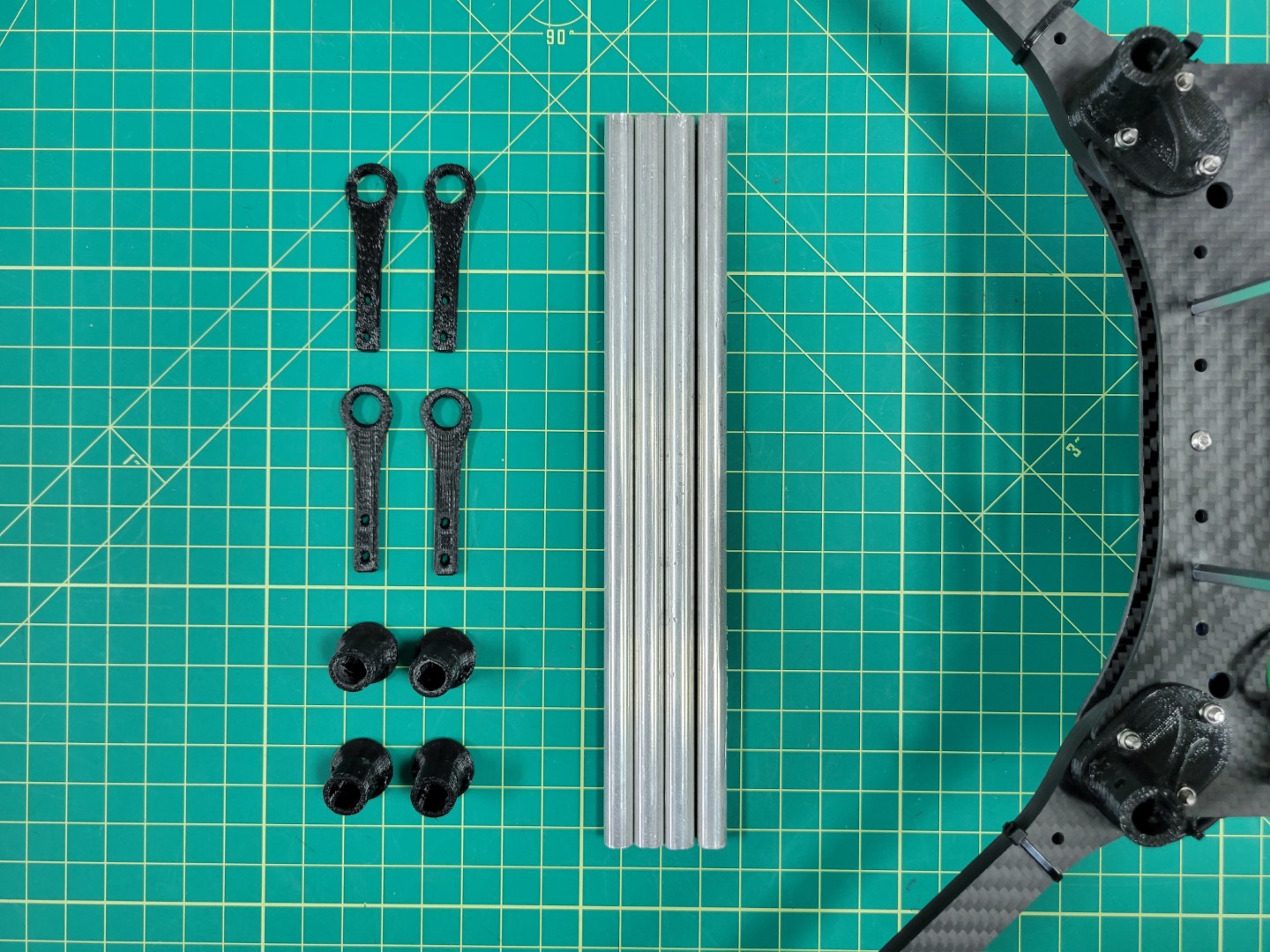
3D printed parts and aluminum rods for landing gear
Attaching the aluminmum rods to the landing gear mounts will require drilling holes in each rod. We will walk through this process in detail to ensure success and minimize frustration. You will need a drill, 1/16" bit, 1/8" bit, screw (or nail), and a Sharpie.
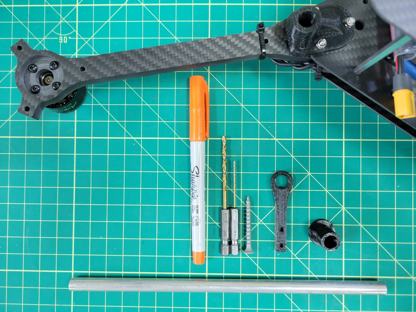
Tools necessary for drilling aluminum rod
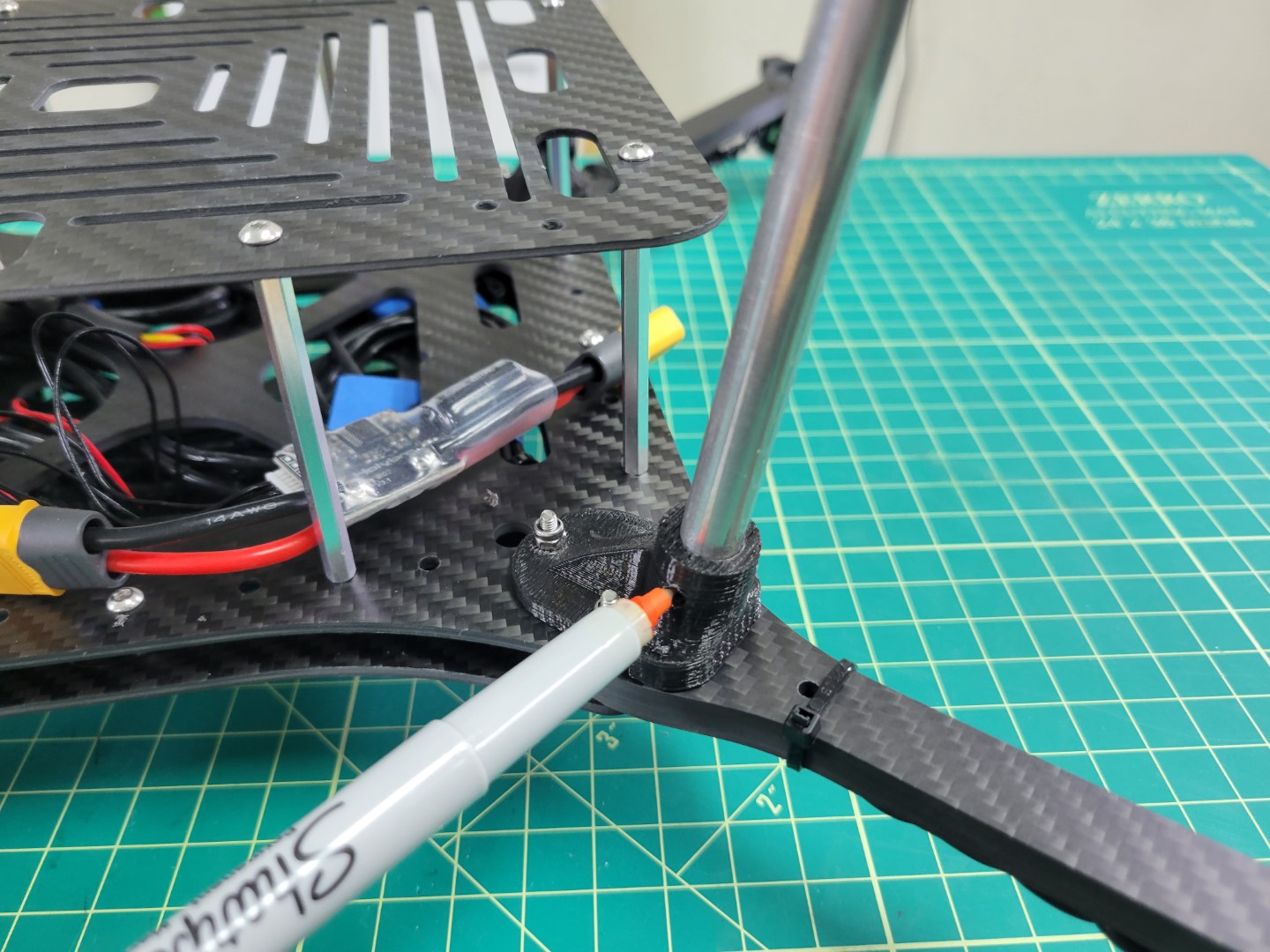
The first thing you will need to do is place an aluminum rod into the landing gear mount as shown below. In most cases this will be a tight fit so we recommend using a bit of force and rotating the rod clockwise and counterclockwise. This will cause some of the plastic from inside the mount to wear away.
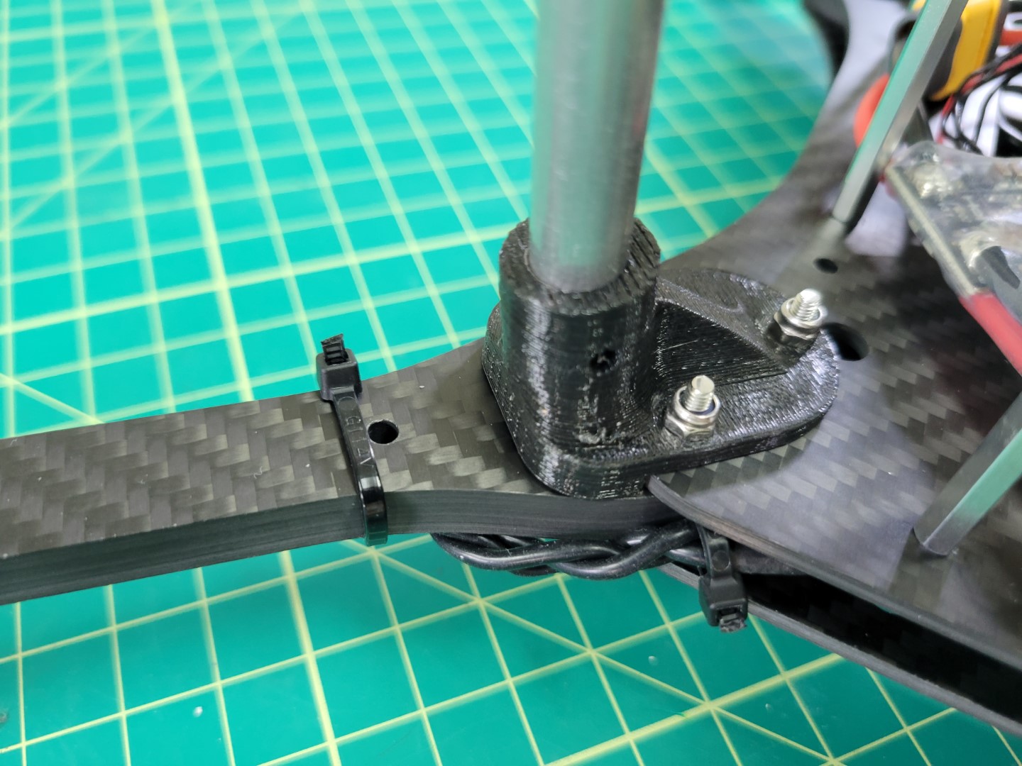
Placing the aluminum rod into the mount
In the photo below you can see some of the plastic shaved off inside the mount.
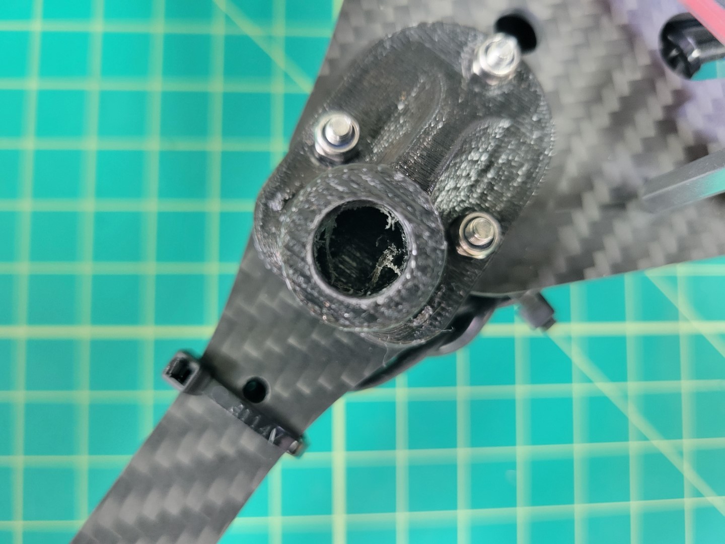
Repeat this process until the rod is flush with the bottom of the mount.
Warning
Use caution as you rotate the rod into the mount. Only use a force perpendicular to the mount. You don’t want to run the risk of cracking the mount and having to print and install a new one.
Tip
If you find this process cumbersome you can try to use a 3/8" drill bit to hollow out the mount. Once again, use caution to prevent the mount from cracking.
Landing gear mount with rod inserted
Use a Sharpie to mark a hole on one side of the rod. Do not mark both sides. There is little margin for error so we will drill one side and repeat this process for the other.
Marking a hole for drilling
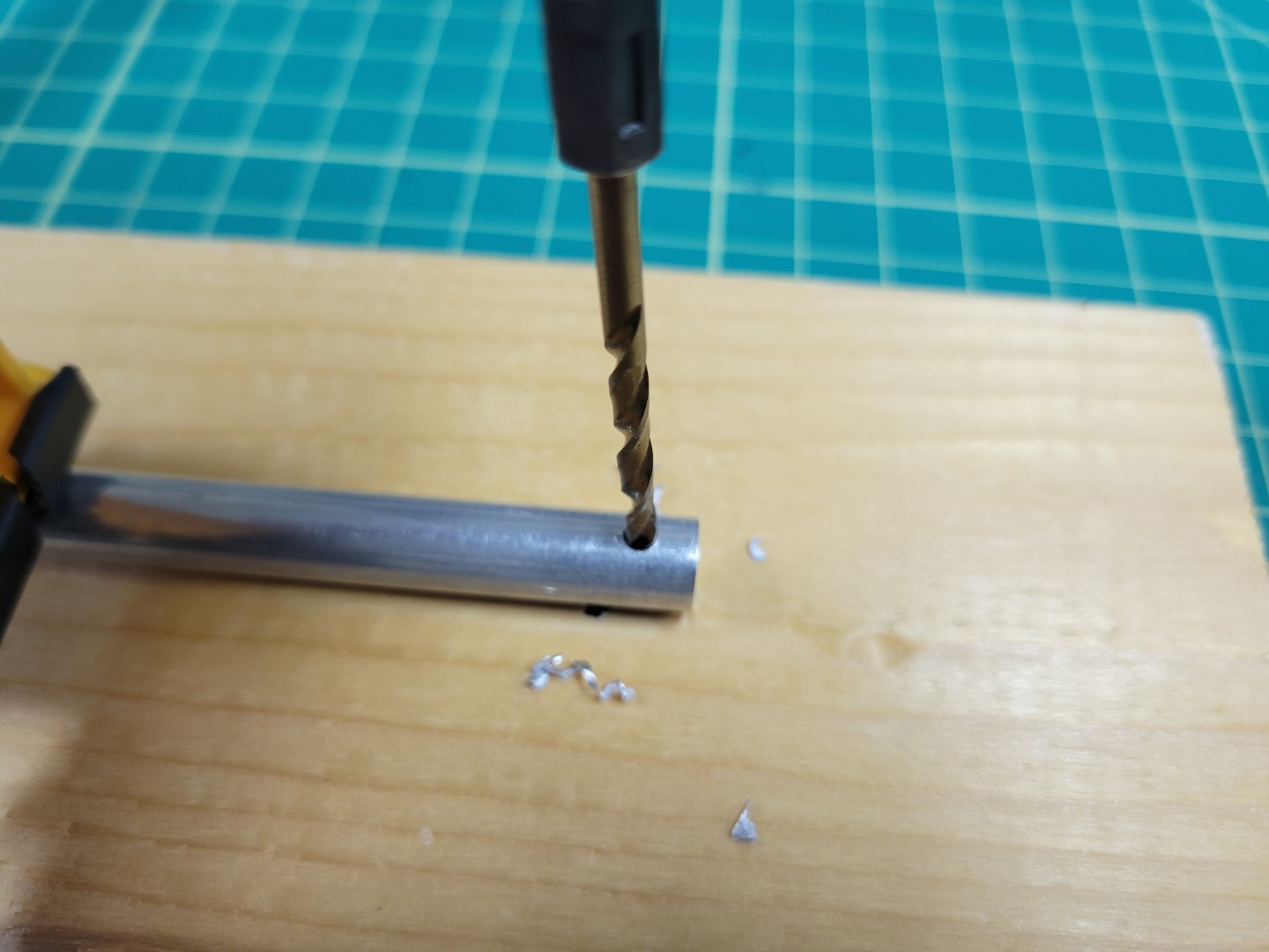
It can be challenging to accurately drill a hole in the aluminum rod. Clamp the rod to a piece of wood and then place a screw or nail in the center of the Sharpie mark. Tap the screw several times with a hammer to create an indentation in the metal.
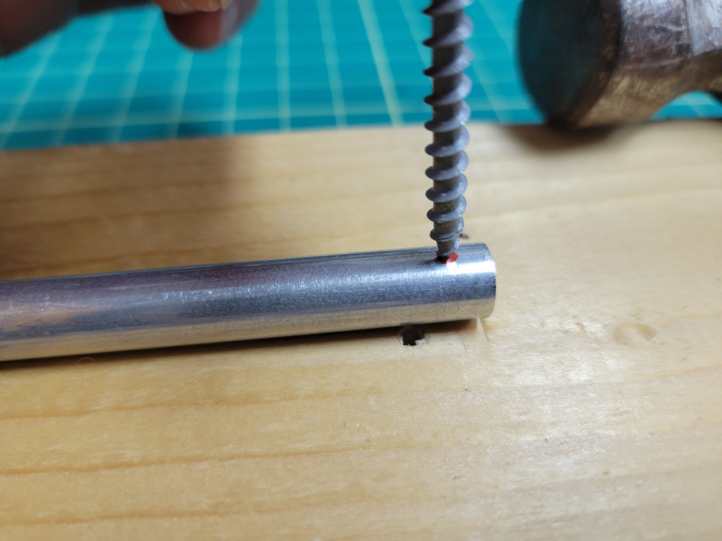
Tapping the screw into the rod
Use the 1/16" bit to drill a starter hole. The indentation you created will keep the bit from slipping around. This drill bit is very fragile so don’t use too much force.
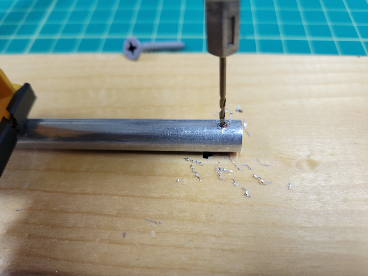
Drilling 1/16" hole in rod
Now use the 1/8" drill bit to enlarge the hole. This will be the final size necessary for our M3 22mm screws.
Drilling 1/8" hole in rod
Place the rod back into the mount make sure it’s all the way in. Slide a 22mm screw through the mount and into the hole you just drilled. Make sure everything fits well and then mark the other side with your Sharpie.
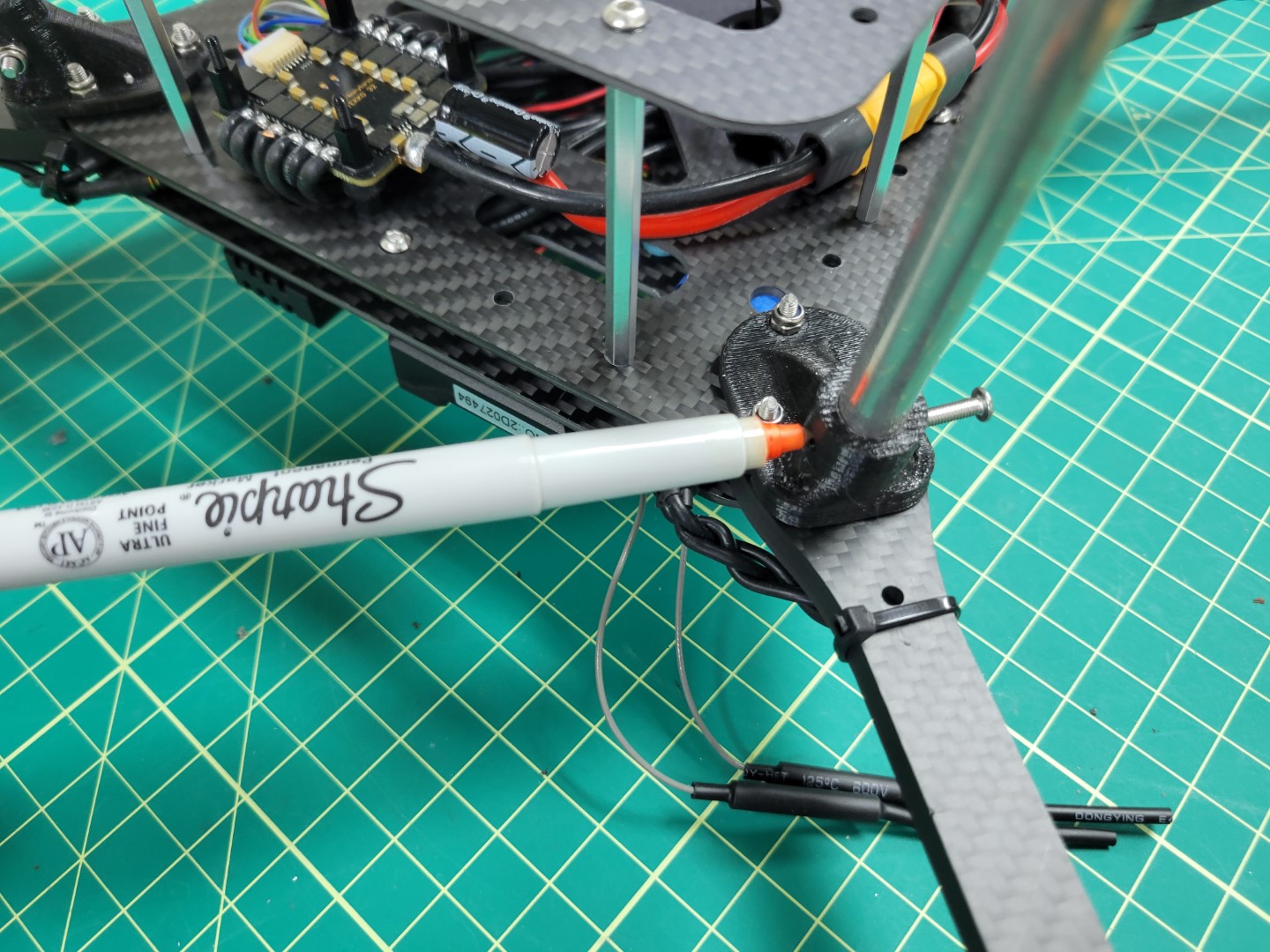
Marking other side of rod for drilling
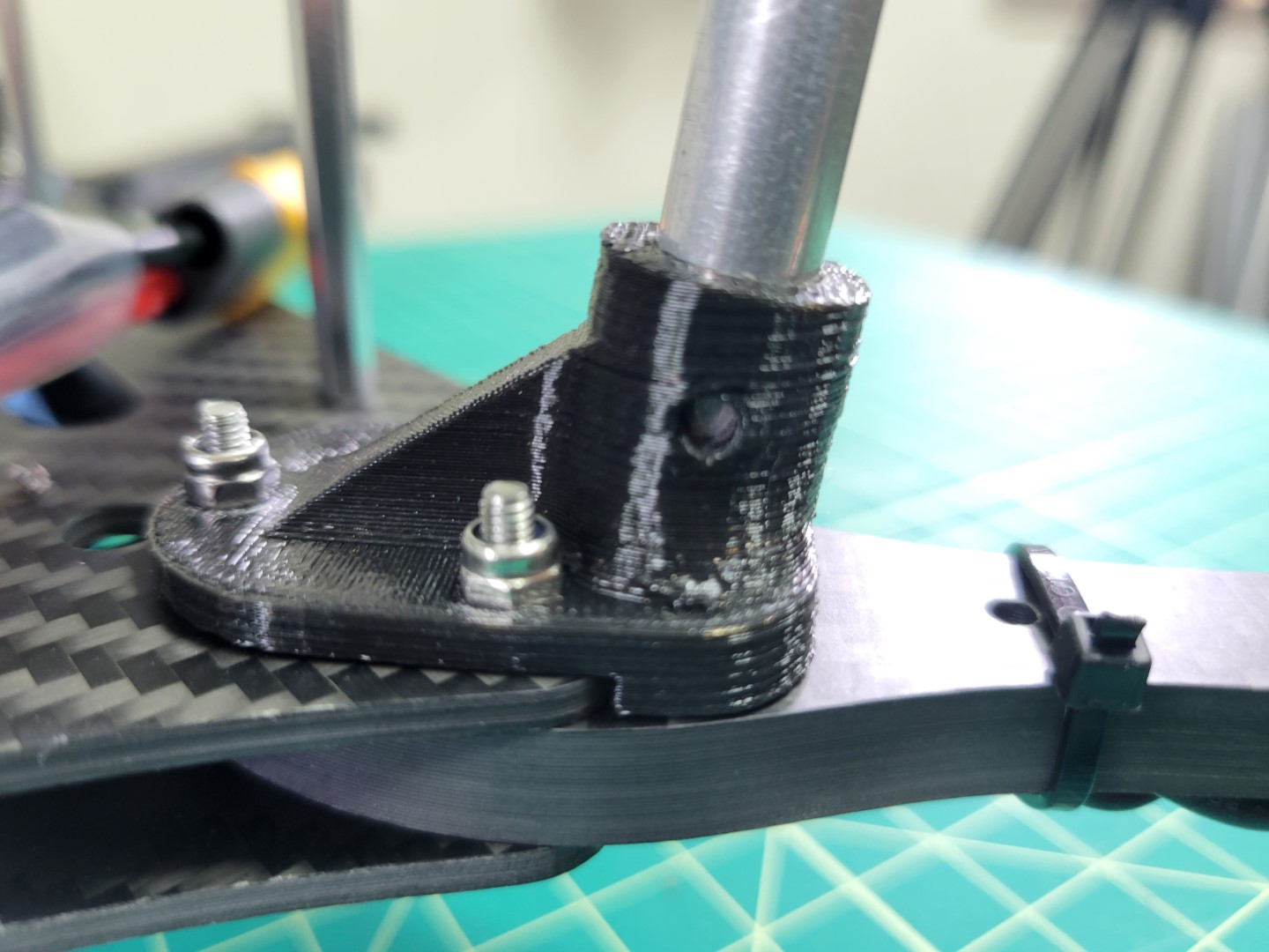
Repeat the tapping and driling process for the other side of the rod. Once that’s complete place the rod back into the mount, slide the 22mm screw all the way through, and secure the rod with a lock nut.
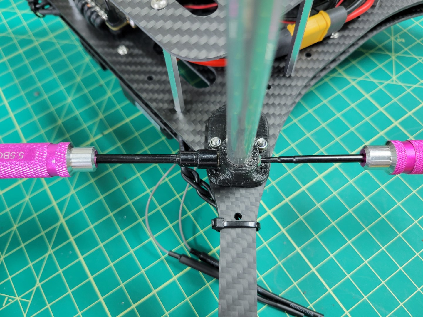
Screwing landing gear into the mount
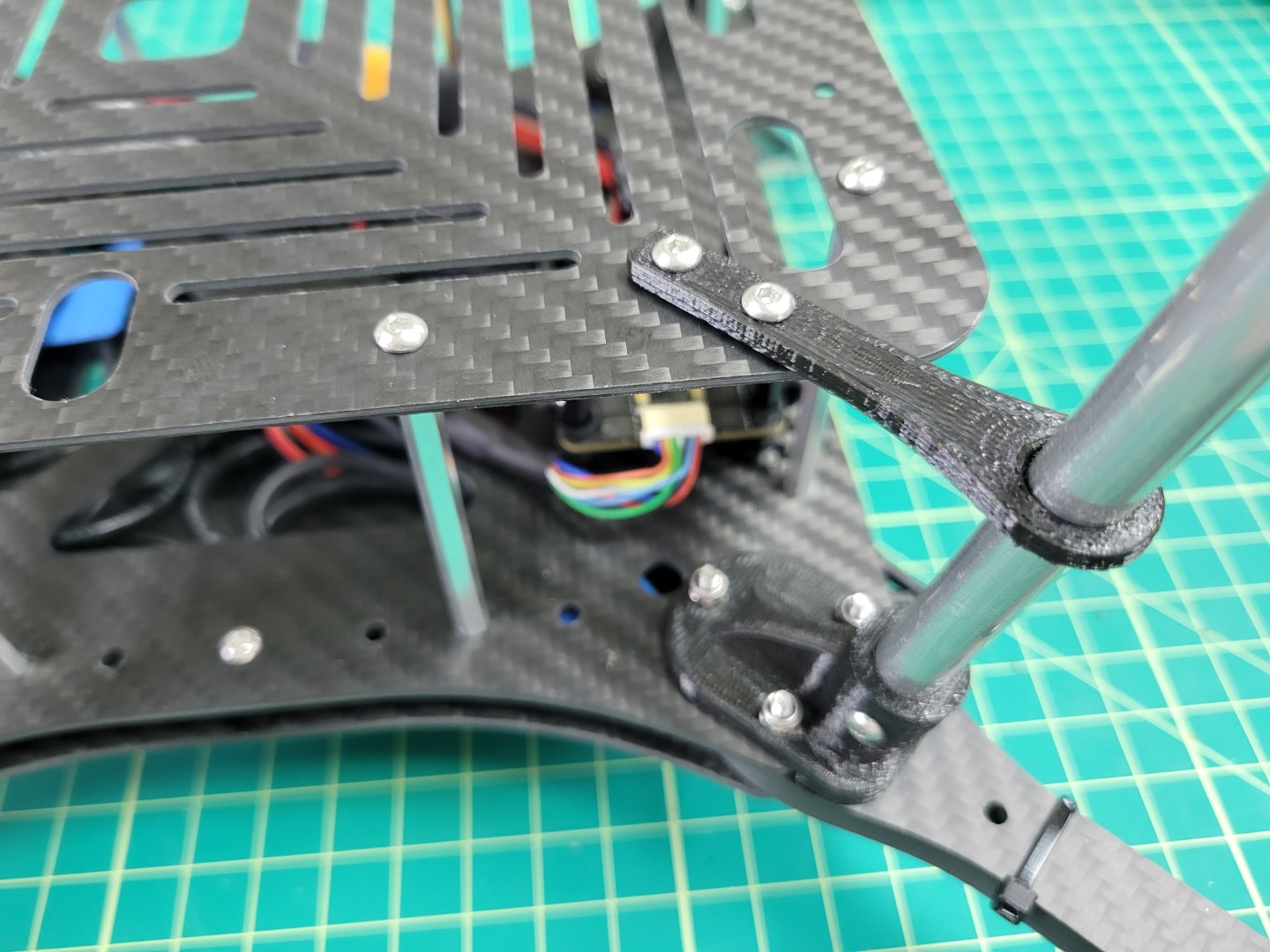
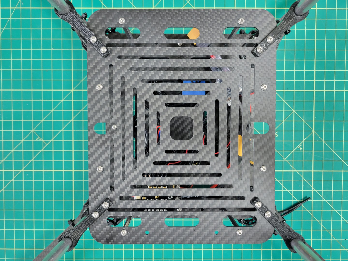
Once all four rods are mounted we will proceed to attaching the landing gear braces which provide extra support.
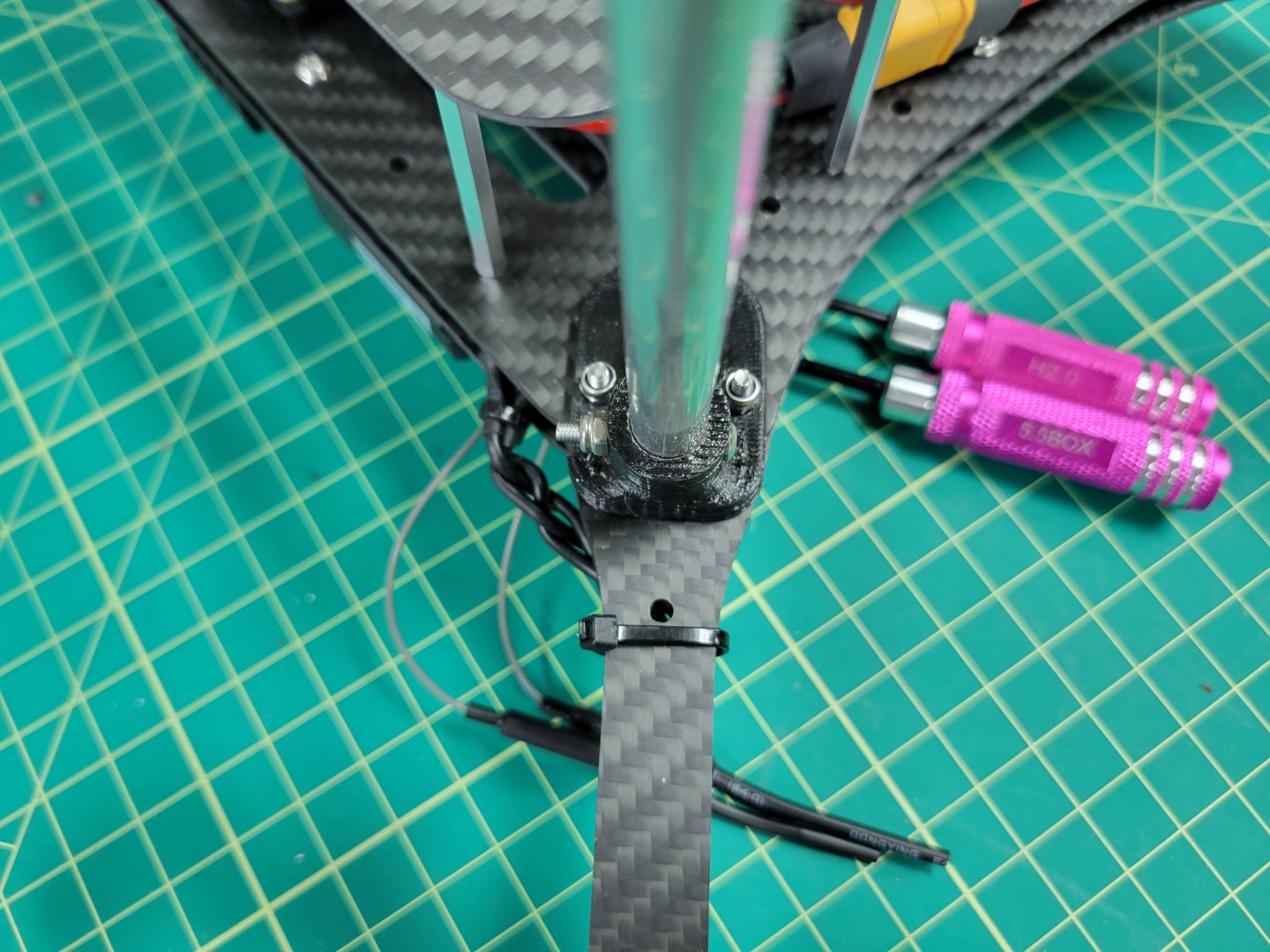
Landing gear securely mounted
Landing Gear Brace Mounting
The landing brace provides additional support by securing the rod to the bottom accessory plate. Use two 8mm screws and lock nuts as shown in the photos below. Repeat this process for all four legs.
8mm screws through landing brace and accessory plate
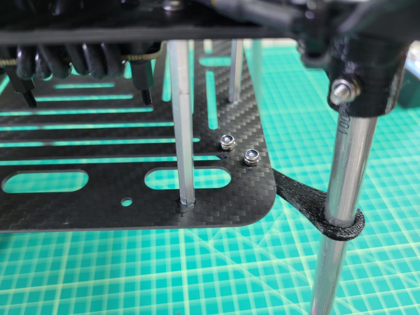
Lock nuts securing landing brace
Landing brace installation complete
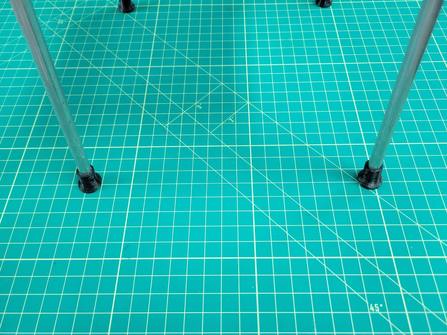
There’s a good chance that the feet of the landing gear will require press fitting onto the rod. You can use a 3/8" drill bit to shave some of the plastic from the foot.
Note
The foot has a slight angle to it. Be sure to rotate it so the bottom of the foot is flush with the floor.
If the foot is loose feel free to use a drop of hot glue to hold it in place.
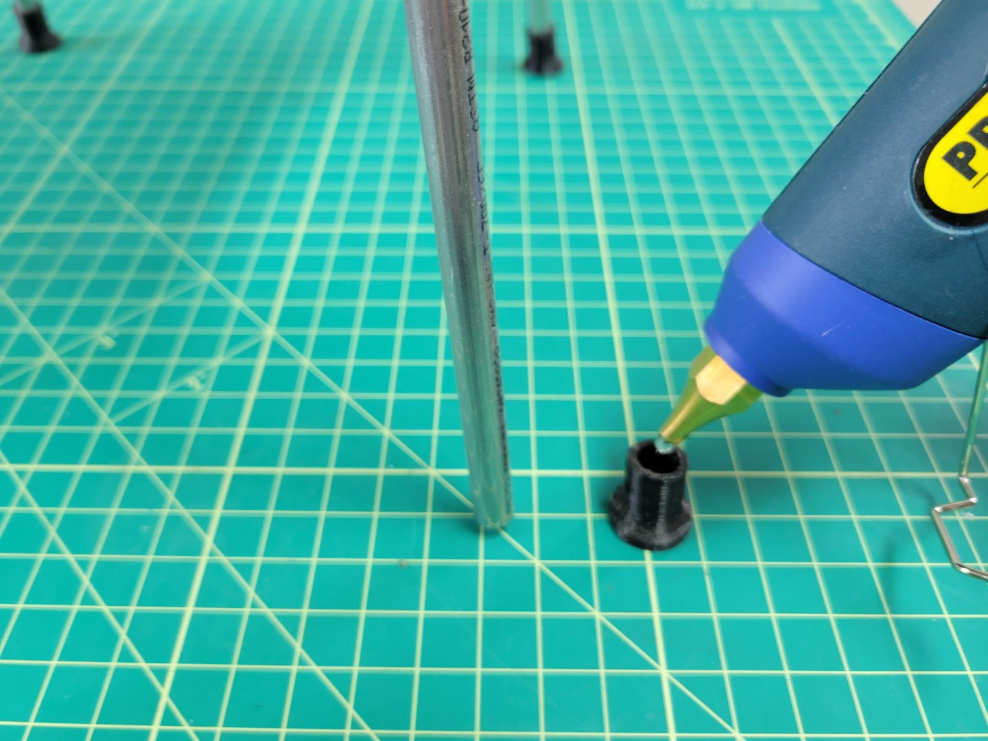
Applying hot glue to landing gear foot
Repeat the process for all four feet.
Landing gear feet installed
Congrats!
You have completed the first part of the build process! Let’s move to the next section to gain a solid understanding of battery management.
8 - Prop Guard Assembly
The prop guards will protect your drone should it inadvertently come into contact with the net.
There are not enough M3 x 22mm bolts included in your kit to assemble the prop guards.
Please refer to notice a bottom of page for solution options.
These instructions use the recommended solution option.
Prop Guard Mounting
This section will guide you through the assembly of the propeller guards.
Warning
Do not attempt to drill or machine carbon fiber motor arms.
Machining will create carbon dust which can cause irritation to skin, eyes, or lungs from fine resin dust particles.
Proper ventilation and respiratory equipment are required to machine carbon fiber components.
Locate the following items below in both your first and second kit shipments.
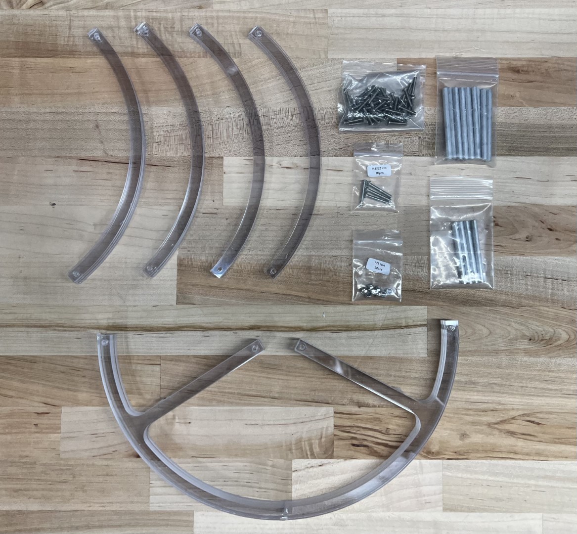
Prop Guard Components and Hardware
Fasten lower prop guard bracket to motor arm using agreed upon method.
Warning
Do not allow wet Loctite to come in contact with the polycarbonate prop guards.
Loctite is caustic to polycarbonate and can cause the prop guards to crack and ultimately fail.
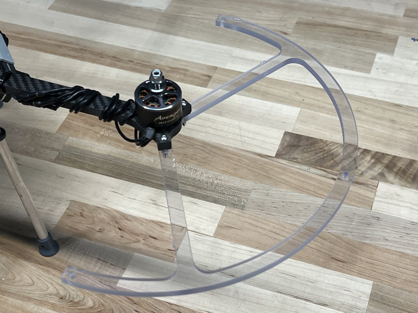
Lower Bracket Fastened to Motor Arm
Fasten a short stand-off to the motor arm hole closest to the drone body arm using the M3 x 15mm bolt.
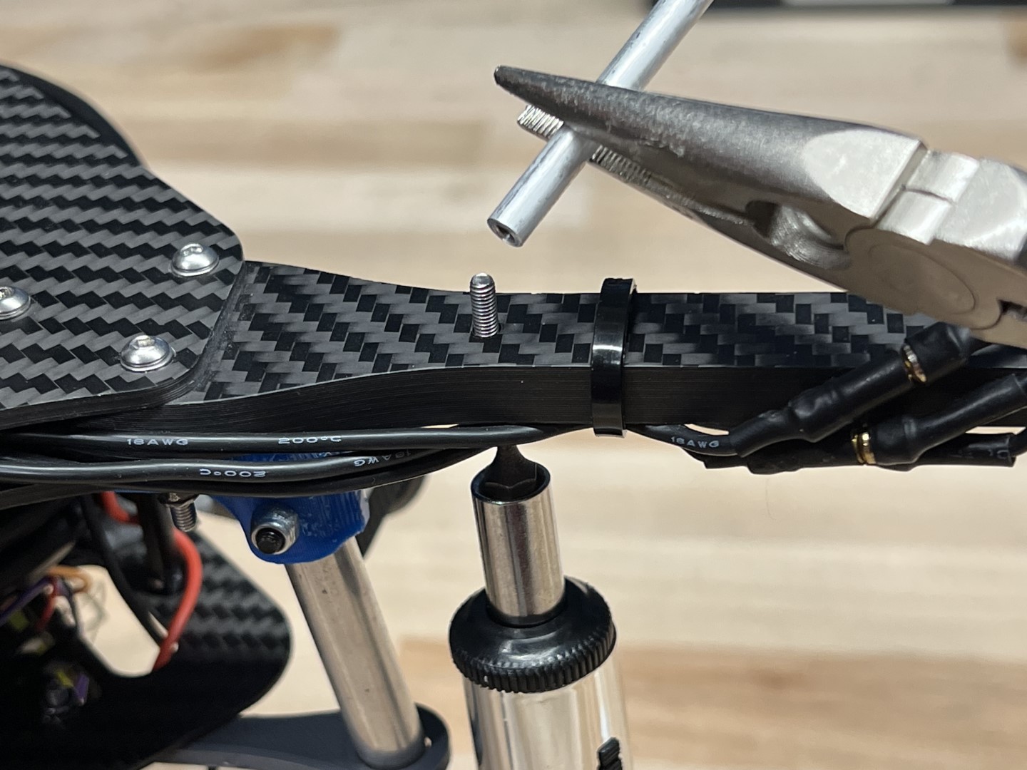
Securing Short Stand-off
Fasten the long stand-offs to the 3 mounting locations on the lower prop guard bracket using the M3 x 15mm bolts.
Securing Long Stand-offs to Lower Bracket
The assembly should match the following photo with the bottom prop guard and all stand-offs mounted.
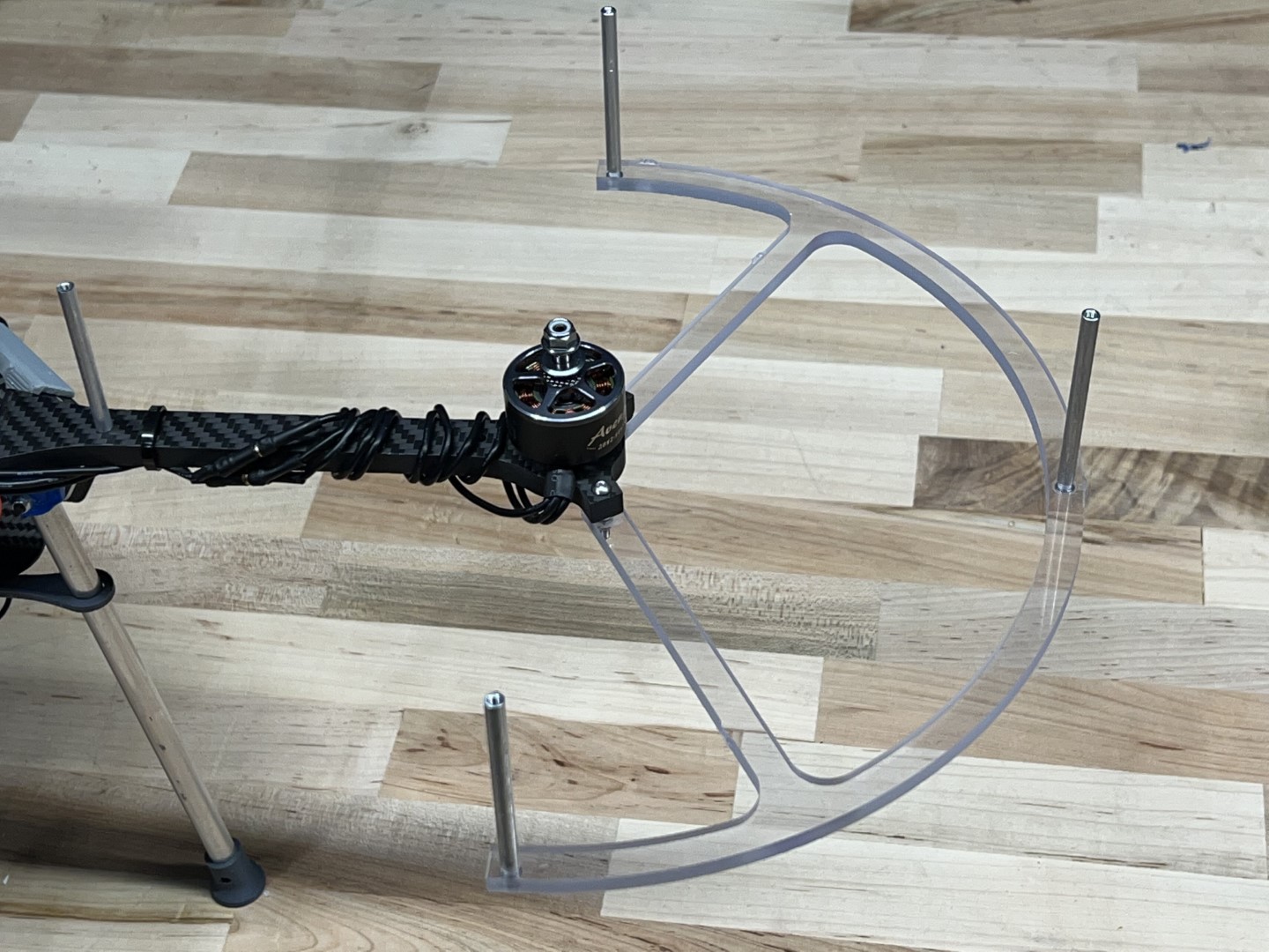
Stand-offs and lower bracket installed
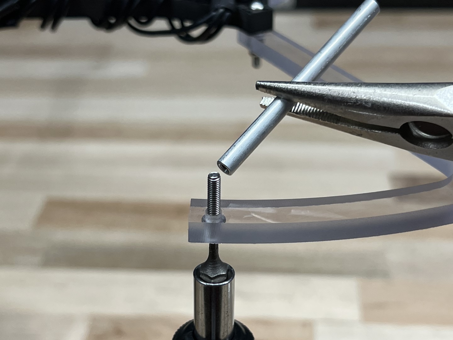
Stack two upper prop guard brackets on top of one another, place a M3 x 15mm bolt through the two holes, and fasten to one of the 4 stand-offs as shown in picture below.
Securing 1st Set of Upper Brackets
Stack the remaining 2 upper brackets such that the upper bracket sits on the lower bracket of the previous step; likewise, the current lower bracket should sit below the upper bracket from the previous step.
Secure the brackets to the stand-off using a M3 x 15mm.
Securing 2nd Set of Upper Brackets
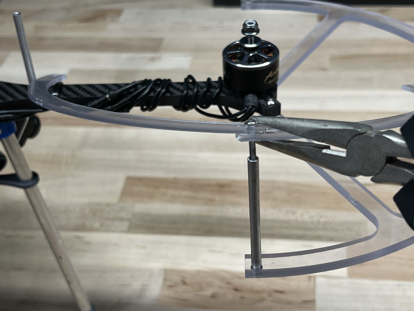
Check that the top brackets are stacked in the correct order and secure to the remaining 2 stand-offs with 2 M3 x 15mm bolts.
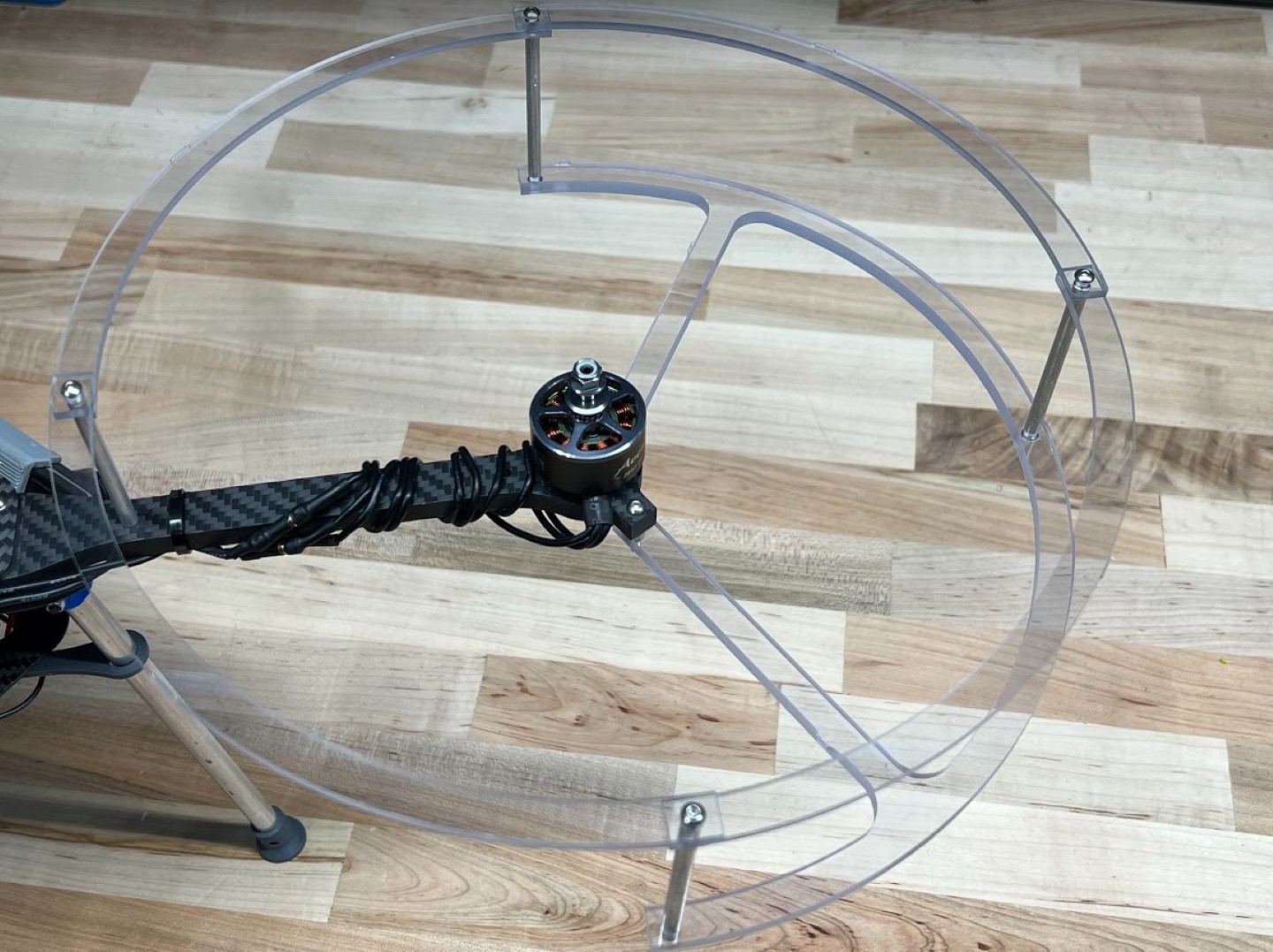
Assembled Prop Guard
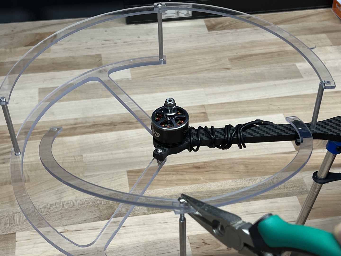
Repeat on the remaining three motor arms.
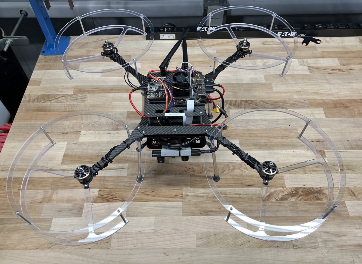
Completed Drone with Prop Guards
Congrats, you have now properly assembled the prop guards to your AVR drone!
Note
There are not enough
M3 x 22mm bolts included in your kit to assemble the prop guards.
Teams may choose from the list of solutions below, but are also encouraged to think of alternative solutions that are not listed.
- Purchase the remaining M3 x 22mm bolts (Recommended solution)
- Pros: Quick fix, doesn’t require any modifications to drone parts
- Cons: Spend money and coordinate travel to store or buy online
- Repurpose the M3 x 22mm bolts currently used on the upper landing gear mounts for mounting the prop guards.
The M3 x 20mm Nylon bolts included in your kit will act as a substitute for the Aluminum bolts on the upper landing gear mount.
- Pros: Does not require purchase of additional supplies
- Cons: Nylon hardware prone to breaking in substitute of Aluminum on landing gear mounting brackets
- Use Nylon M3 x 20mm bolts and nuts included in your kit to fasten prop guards to motor arms
- Pros: Does not require purchase of additional supplies
- Cons: Nylon hardware prone to loosening in a high vibration environment next to the motor.
Loosening can be prevented by using a non-loctite thread locker applied to Nylon nuts and bolts. (See previous note about loctite being caustic to poly carbonate.)
- Counterbore prop guard motor arm mounting holes to accommodate shorter length Aluminum fasteners included in your kit.
- Pros: Does not require purchase of any additional supplies.
- Cons: Run the risk of ruining prop guard components if done improperly, it is aesy. If this approach is attempted, a drill press and appropriately sized end mill are suggested to perform this operation.