Overview
Two main components of your advanced build are the Vehicle Management Computer (VMC), which runs the AVR software stack and the Peripheral Control Computer (PCC), which will allow teams to manually and programmatically control the LED ring, actuate up to four servos, and control the laser.
This section will walk through the necessary steps for providing adequate power to both the VMC and PCC. This will be done with two separate buck converters. The main battery of your AVR drone is 16.8V fully charged. The required input voltage for the VMC and PCC are 5V, therefore the buck converters will step the voltage down to a usable 5V.
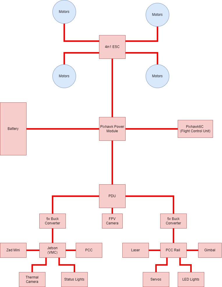
Power Wiring Diagram
This section will work its way from the battery out to the VMC & PCC.
Y-Cable
The Y-cable is the cable that splits the battery power into two directions: one for the ESC, and one for the PDB.
To create the wire cables use 3 of the 4 pre-soldered XT60 cables from the kit, 2 females and one male.
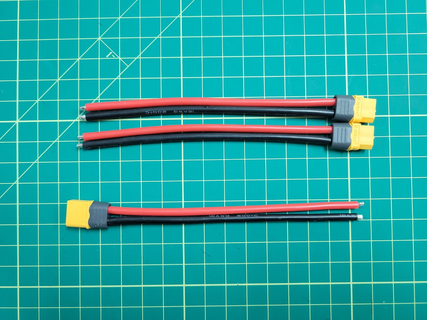
XT60 cables
XT60 male (left) and female (right) connectors
Firstly, cut each cable to approximately 2 inches and solder the ends so that they are ready to combine. The end result should look similar to the following.
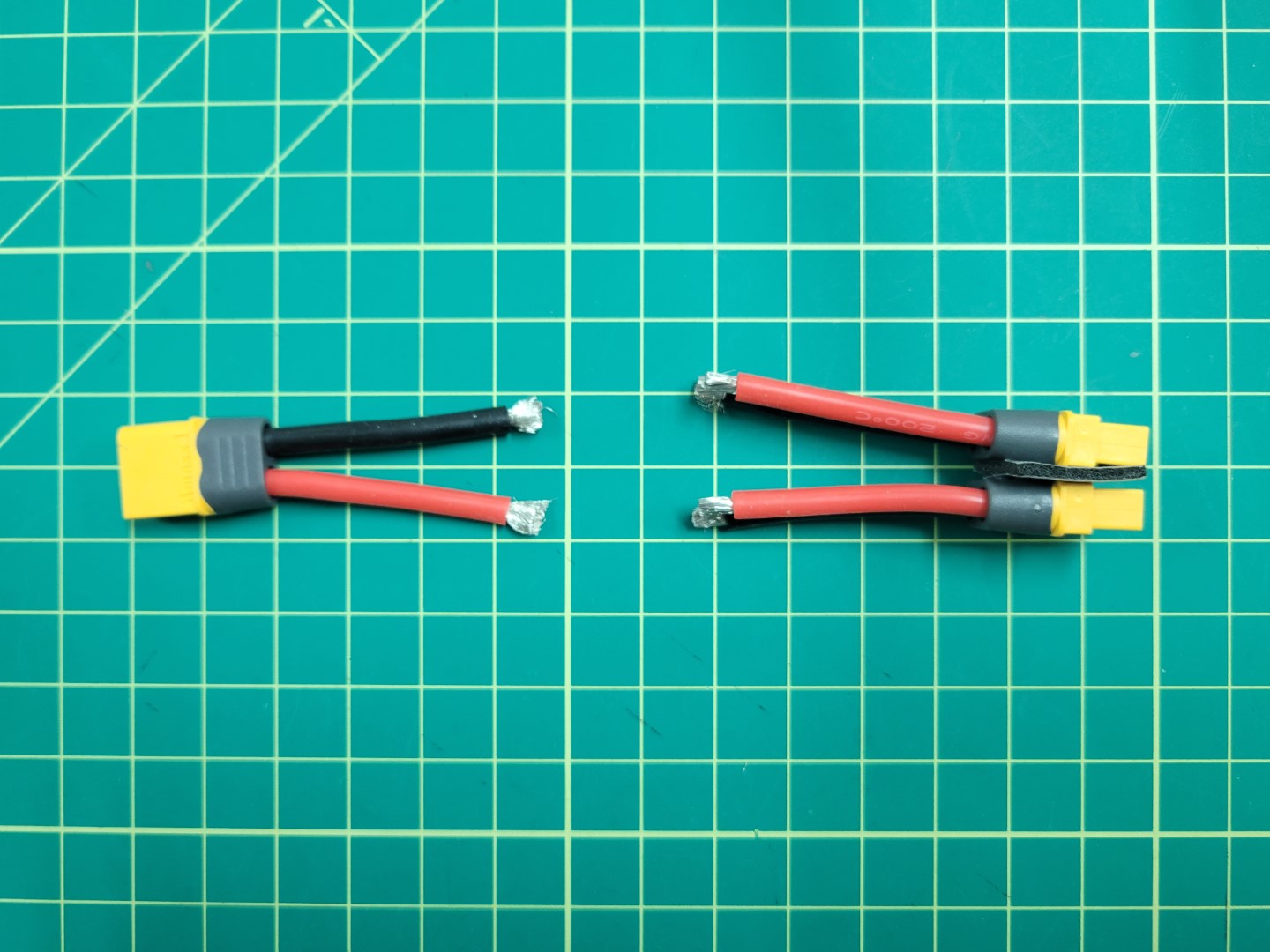
XT60 cables preparation
Next, place heat shrink large enough to slide over the 3 cable solder joint on the side with 1 male connector. Then, solder the 3 ground (black) cables together. Pull the heat shrink down over the end of the connection and apply heat. If you have access to a heat gun or a lighter this will work well. Alternatively, you can use the side of your soldering iron to apply heat and let the tubing shrink over your connectors.
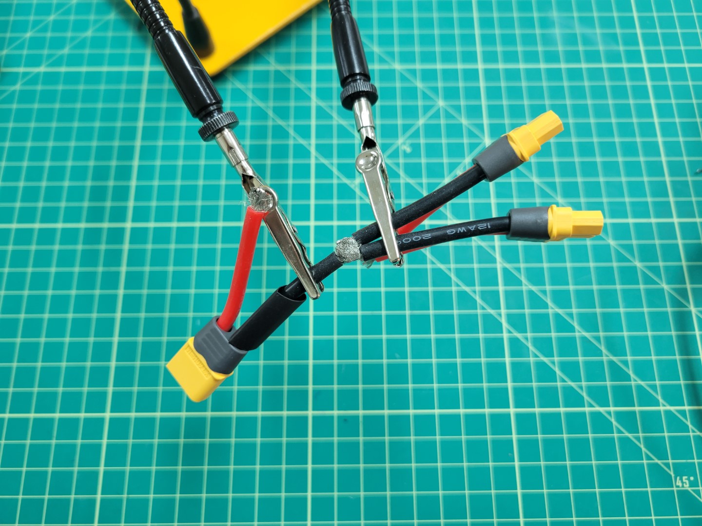
Soldering XT60 cables
Repeat for the voltage (red) cables.
Soldering XT60 cables
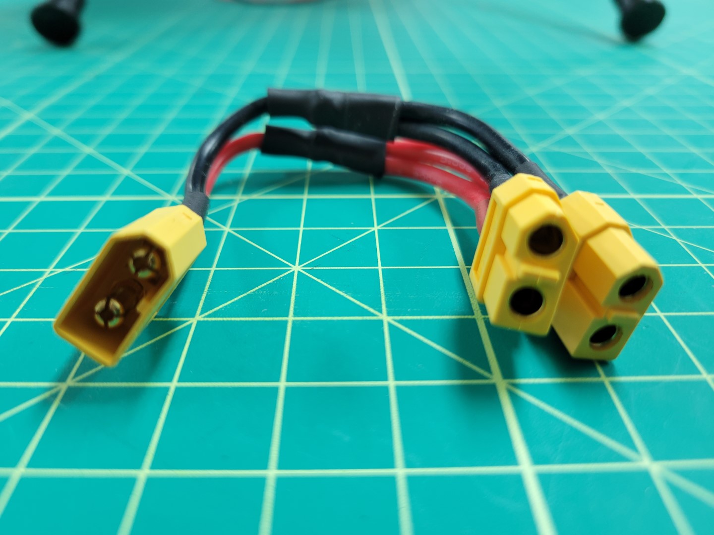
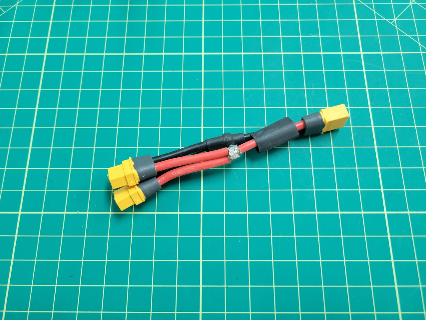
Your finished cable should look like the photo below.
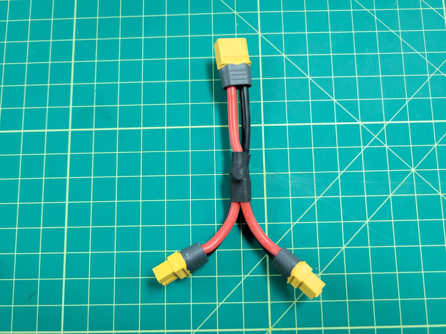
Y cable with 1 male and 2 female connectors
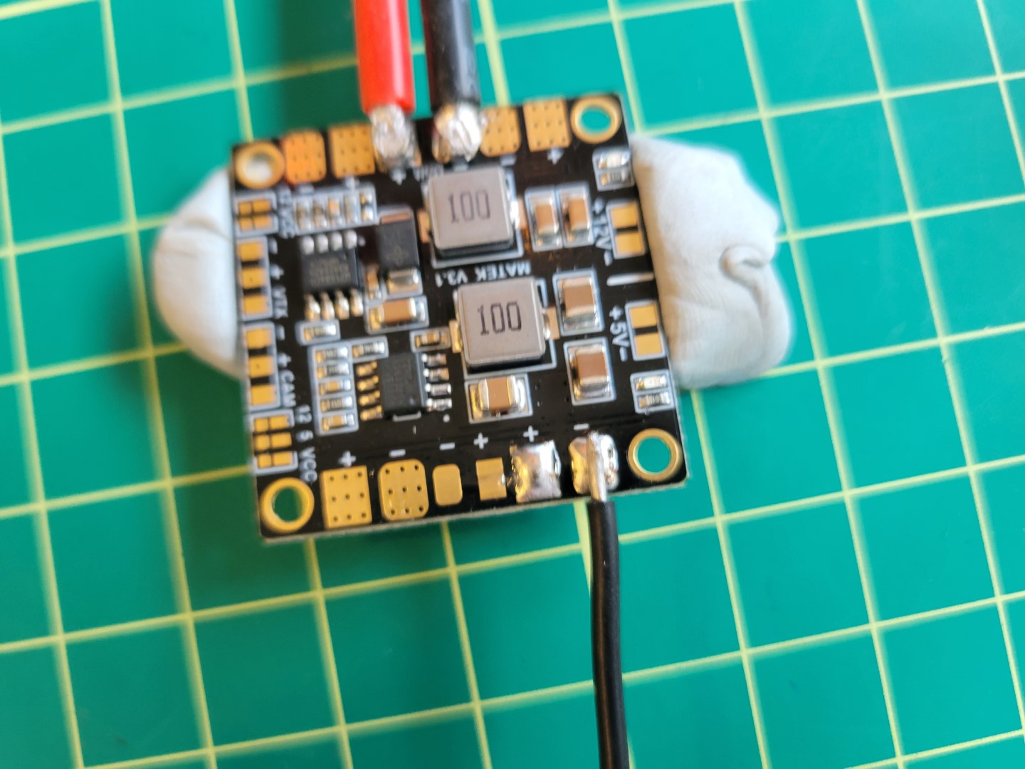
PDB Input Soldering
Before installing the buck converters, the Power Distribution Board (PDB) will need to be soldered correctly. The PDB will allow us to split off power from the battery to each of the buck converters.
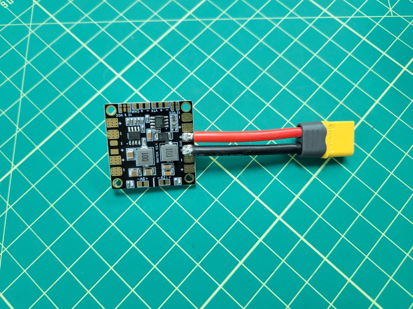
The first step is to solder on the battery leads to the PDB. To do this cut 1 male XT60 cable to about 2 inches and tin the ends as we did with the y-cable above.
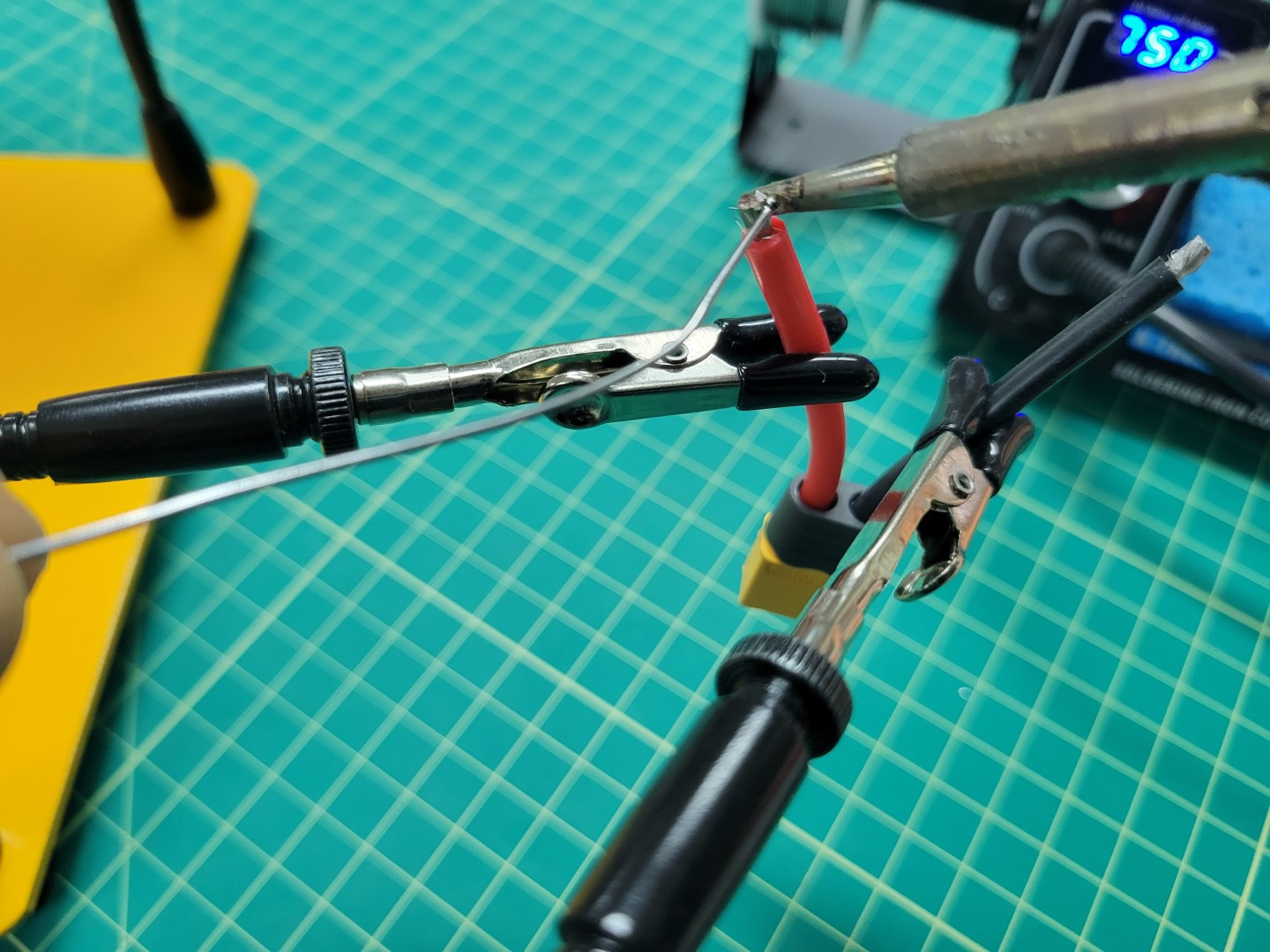
Tinning male XT60 leads
Warning
Soldering the larger pads on the PDB requires skill and patience. If possible, we recommend using a flat tip on your iron instead of the normal pointed tip. This will allow for much better heat transfer.We recommend watching this video that goes into great detail on soldering. It’s lengthy so at the very least you should scrub through it before attempting to solder the XT60 to the PDB.
You do not want the PDB to slide around while soldering. One of our favorite tricks is to use Blu Tack to hold components in place.
Start the process by tinning the Batt +/- pads as shown in the photos below. A good temperature to aim for is between 750 and 800 degrees Fahrenheit.
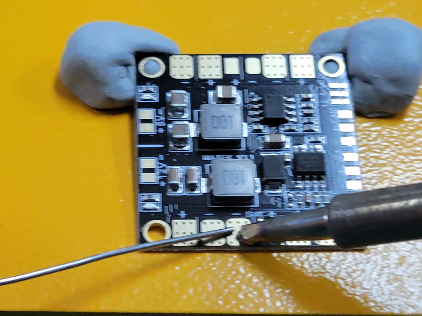
Tinning PDB batt +/- pads
Pads tinned and ready for input wires
Place the positive wire onto the positive pad and set the tip of the iron on top. Do not apply too much pressure as you do not want the wire to spread out. The iron should heat both the wire and the pad to form a single solder joint.
Animation of soldering wire to PDB pad
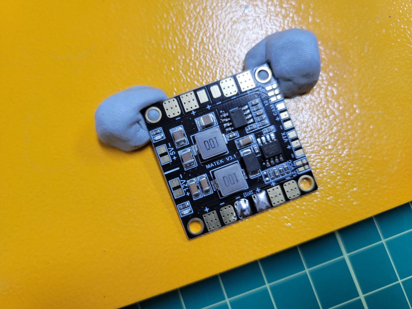
Repeat this process for the negative wire. Your completed PDB will look similar to the one below.
PDB input soldering complete
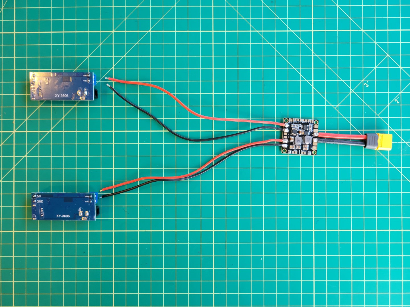
PDB Output Soldering
In the photo below you will notice two identical buck converters, one for powering the VMC and the other for the PCC. This section will walk through the necessary wiring to supply power to the buck converters.
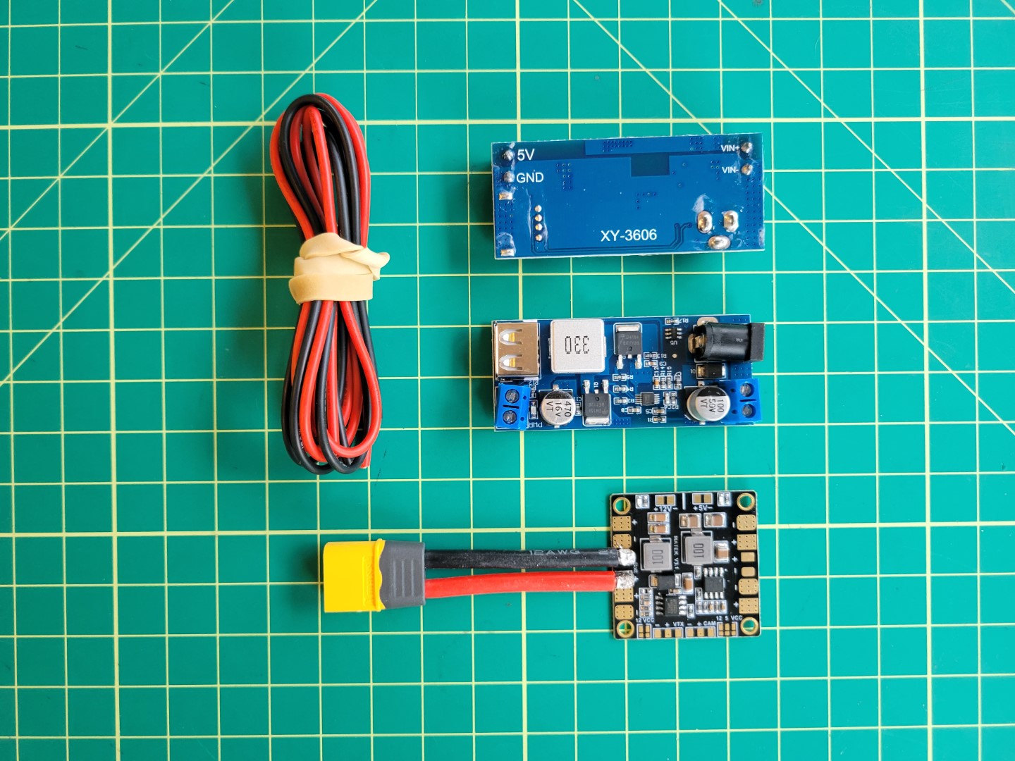
PDB, wires, and buck converters
Cut approximately 8" of wires; 2 black and 2 red. These will be used to connect each of the buck converters to the PDB. On the opposite end of the PDB there are two sets of pads that we’ll tin for soldering.
Heat the pad using the tip of the soldering iron and feed the solder onto the pad as shown in the photo below.
Soldering the PDB
Once the pads are pre-tinned it should like the following.
Pre-tinned Solder Pads
Next, apply solder to the wires to pre-tin them.
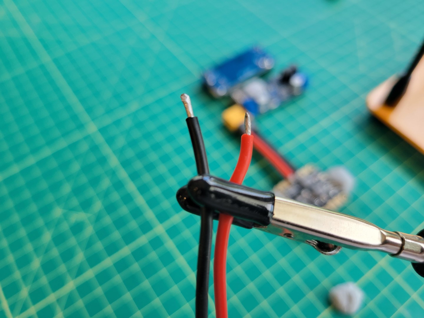
Pre-tinned Wires
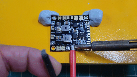
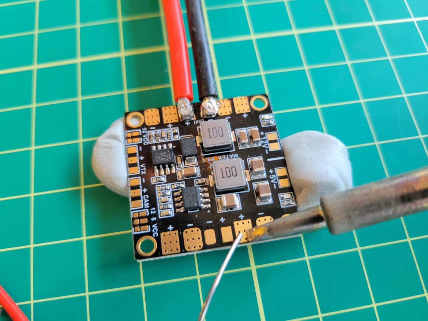
After pre-tinning everything, place each lead on the corresponding pad and gently push the soldering iron down. Like we did with the XT60 connector we want to make sure to apply heat long enough for the solder on the pad and wire to join.
Soldering wires to pads
Repeat this process for the other two wires. After successfully soldering the positive and negative wires to the PDB, use a multimeter to run a continuity test. This will ensure that there are no shorts between the positive and negative terminals.
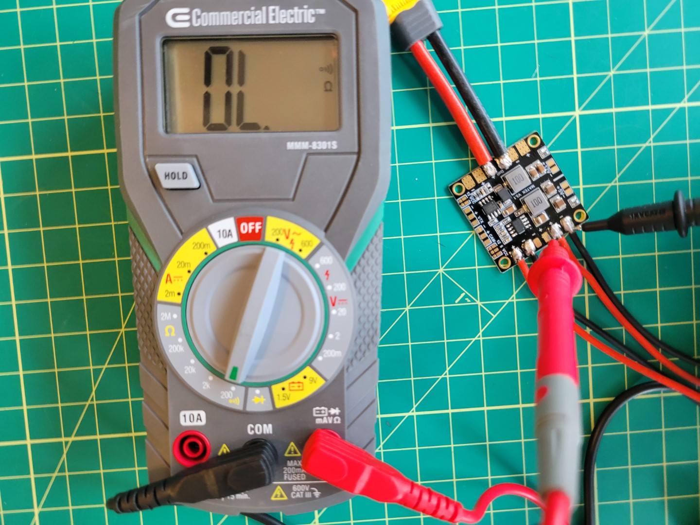
Checking connections
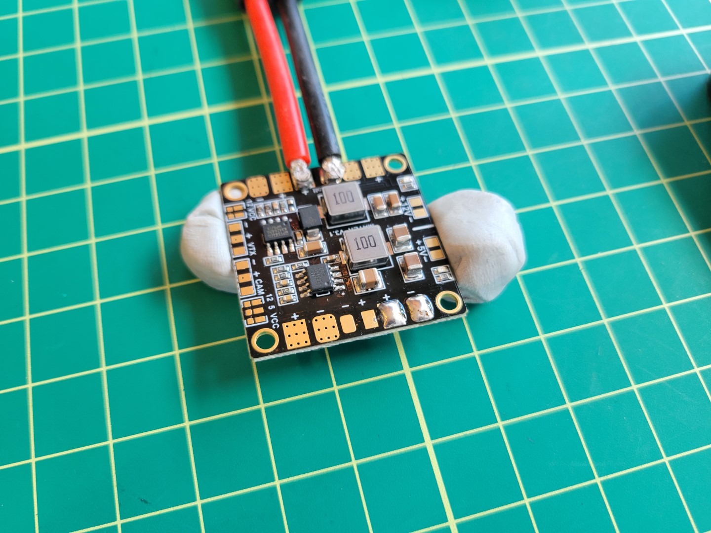
You should now be at a place where you have the PDB soldered as shown in the following photo.
Power Distribution Layout
Finally, place the PDB on top of the ESC standoffs and secure using M2.5 nuts from your AVR kit.
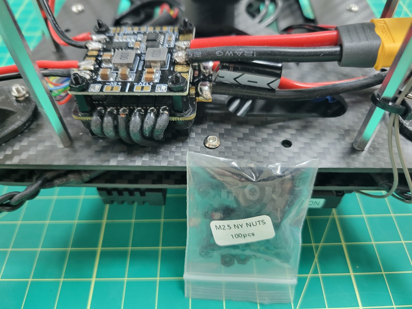
Mounting the PDB