This is the multi-page printable view of this section.
Click here to print.
Return to the regular view of this page.
Advanced Drone Assembly
Please make sure you’ve successfully built and flown your basic AVR drone.
You will be making some extensive modifications to your drone in
preparation for advanced assembly.
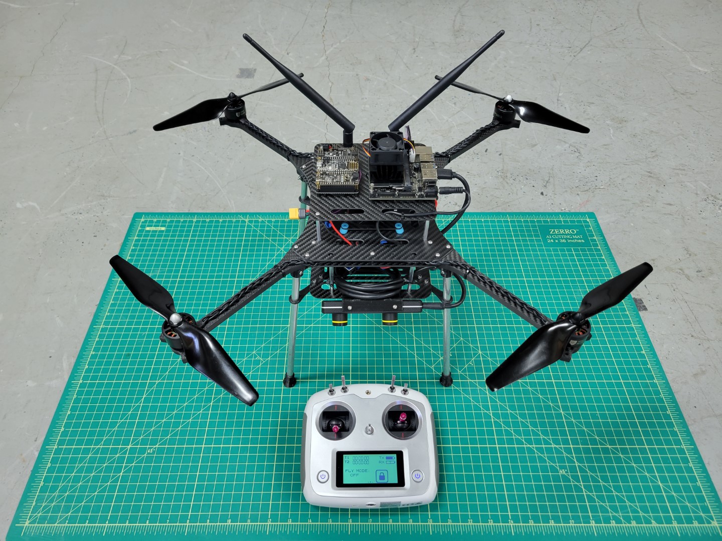
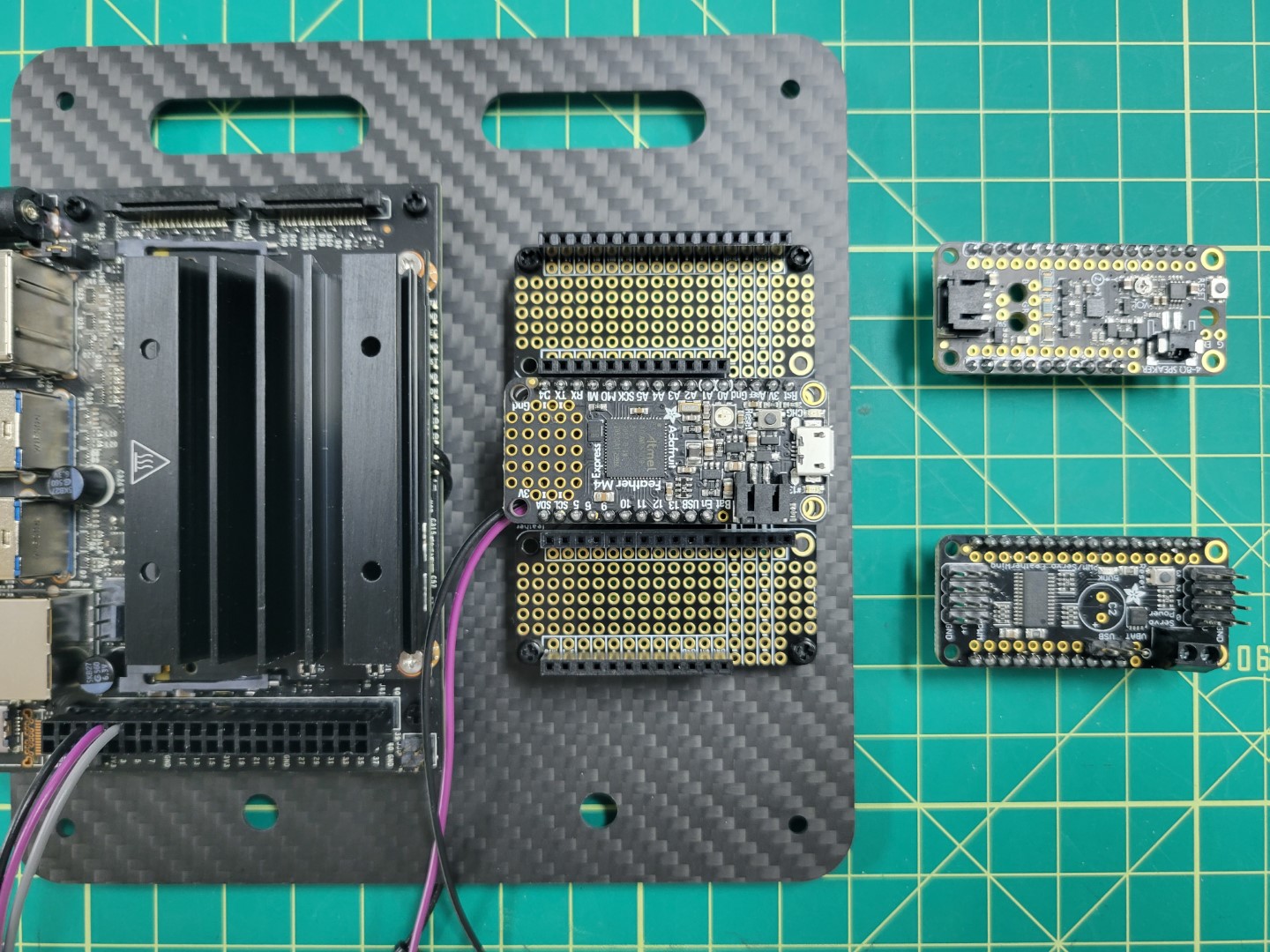
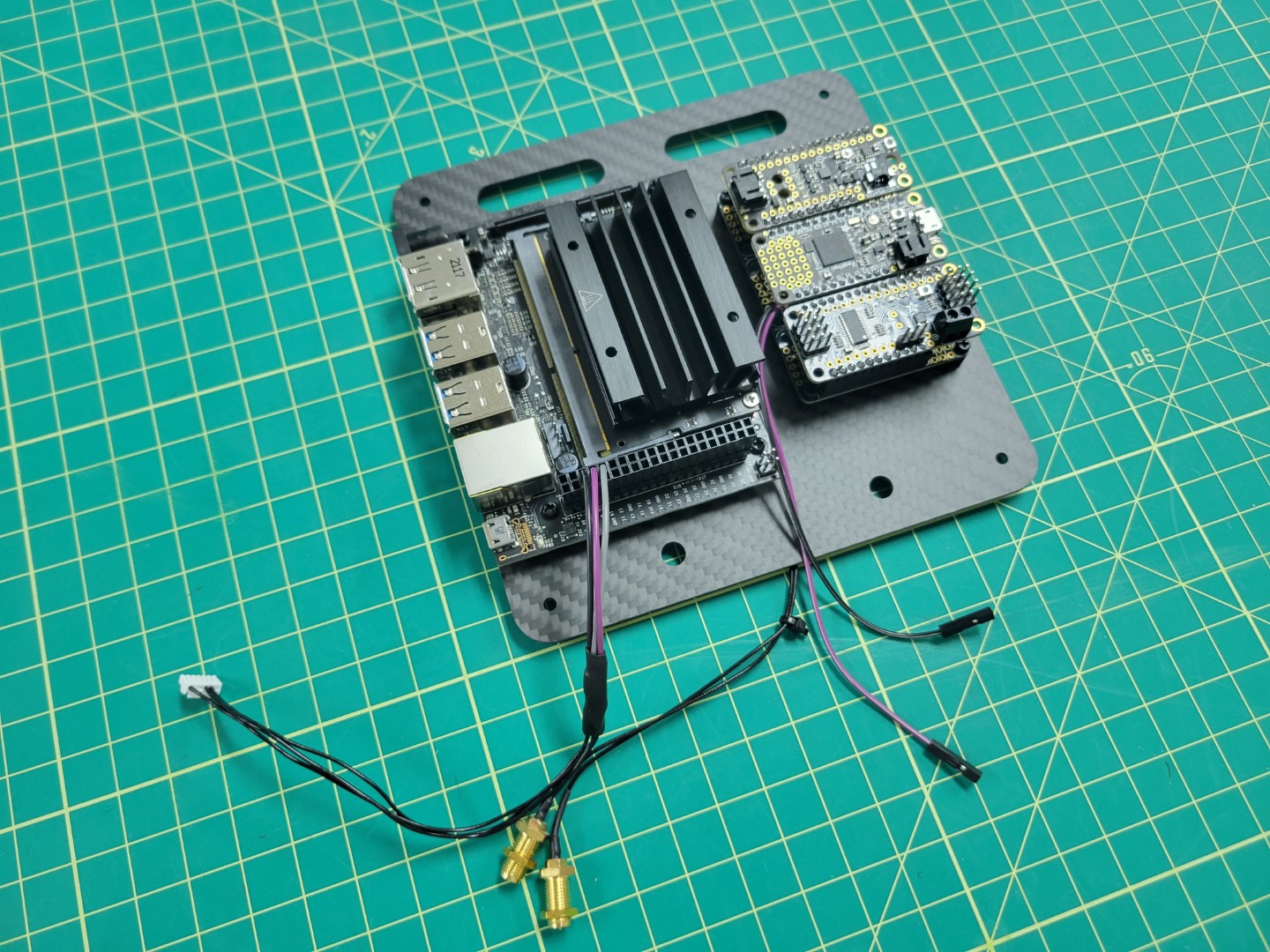
AVR advanced drone assembly (front)
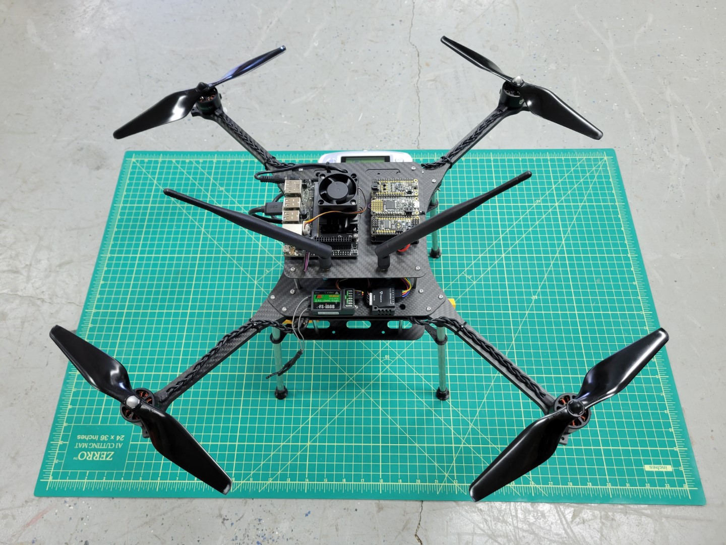
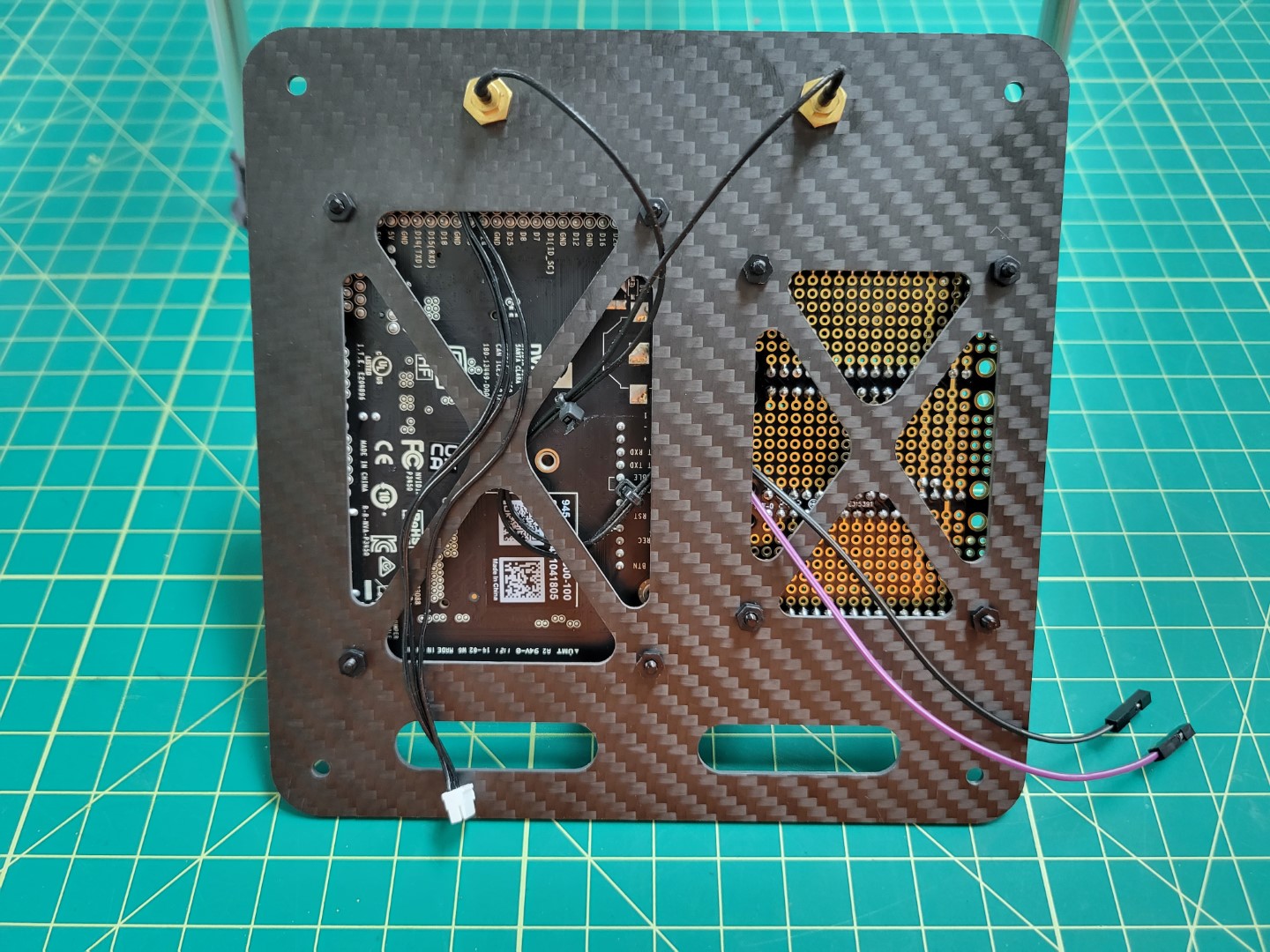
AVR advanced drone assembly (back)
The modifications for advanced assembly will require some disassembly and the following
additions to your drone:
- 3D printed components
- For mounting various cameras and peripherals
- Power setup for VMC and PCC
- Power distribution board soldering
- Y-cable to split power between PDB and ESC
- Buck converters for powering VMC and PCC
- Telemetry cable
- For communication between VMC and FC
- Vehicle Management Computer (VMC)
- Runs AVR code
- Interfaces with external sensors
- Provides wireless interface with PX4
- Peripheral Control Computer (PCC)
- For LED and servo actuation
- ZED Mini Tracking Camera
- For real-time mapping of the environment
- For position hold
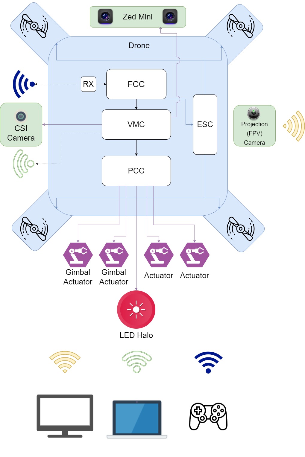
Block Diagram for the Advanced Drone
1 - VMC and PCC Power
Overview
Two main components of your advanced build are the Vehicle Management Computer (VMC), which runs the AVR software stack and the Peripheral Control Computer (PCC), which will allow teams to manually and programmatically control the LED ring, actuate up to four servos, and control the laser.
This section will walk through the necessary steps for providing adequate power to both the VMC and PCC.
This will be done with two separate buck converters.
The main battery of your AVR drone is 16.8V fully charged.
The required input voltage for the VMC and PCC are 5V,
therefore the buck converters will step the voltage down to a usable 5V.
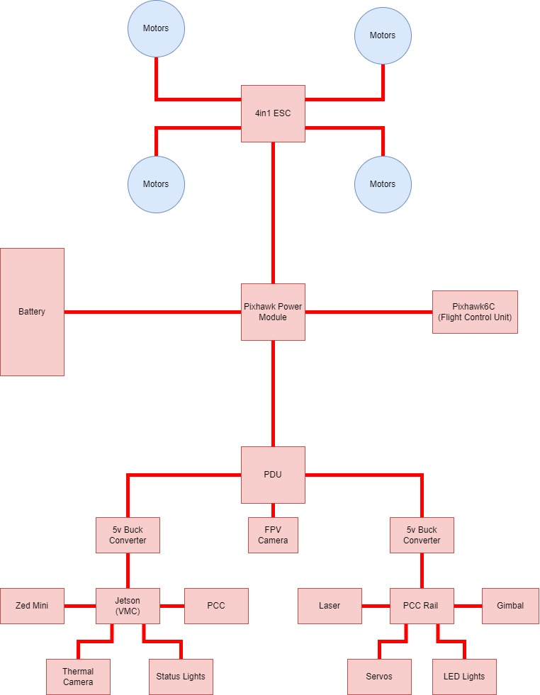
Power Wiring Diagram
This section will work its way from the battery out to the VMC & PCC.
Y-Cable
The Y-cable is the cable that splits the battery power into two directions: one for the ESC, and one for the PDB.
To create the wire cables use 3 of the 4 pre-soldered XT60 cables from the kit, 2 females and one male.
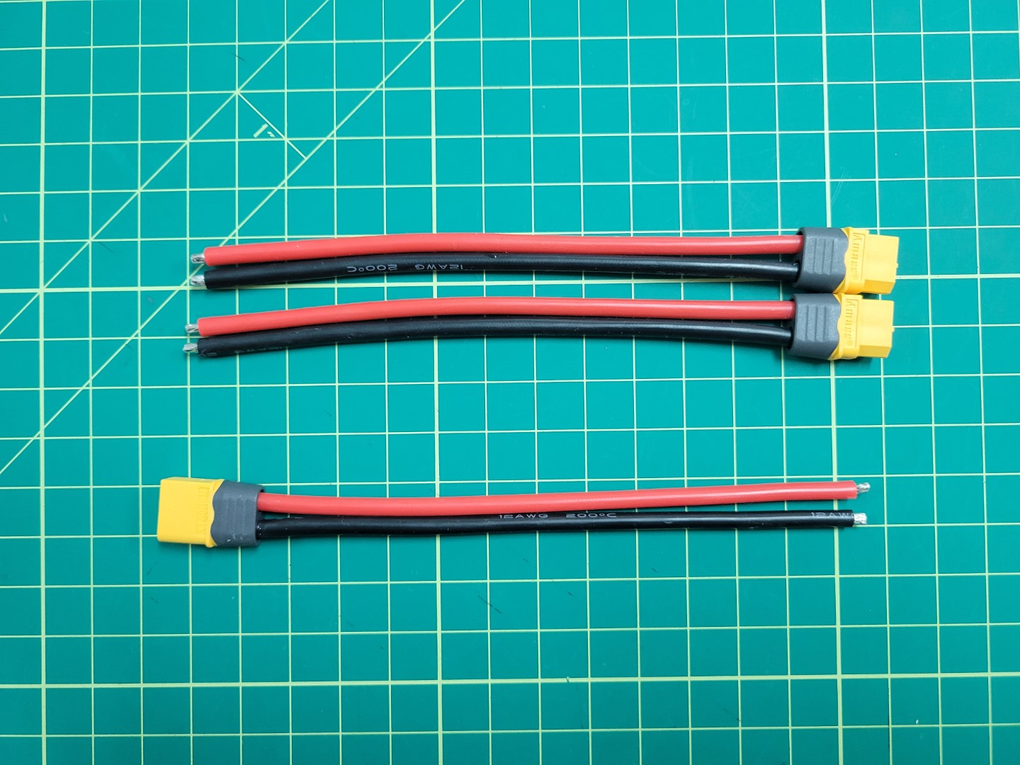
XT60 cables
XT60 male (left) and female (right) connectors
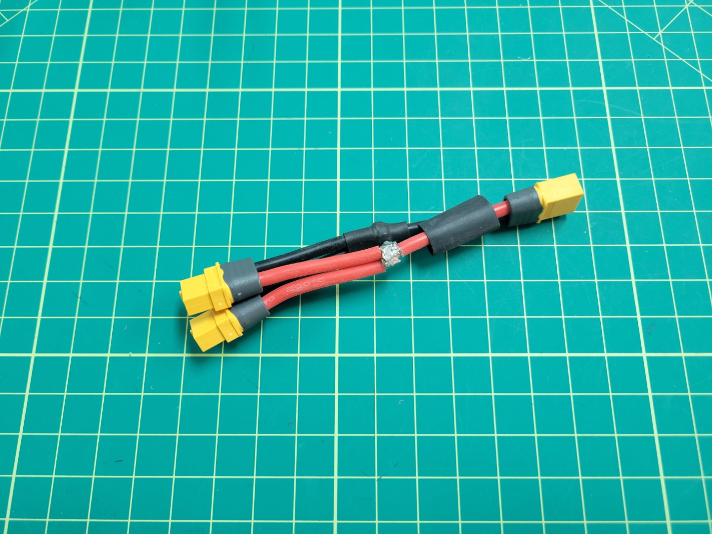
Firstly, cut each cable to approximately 2 inches and solder the ends so that they are ready to combine. The end result should look similar to the following.
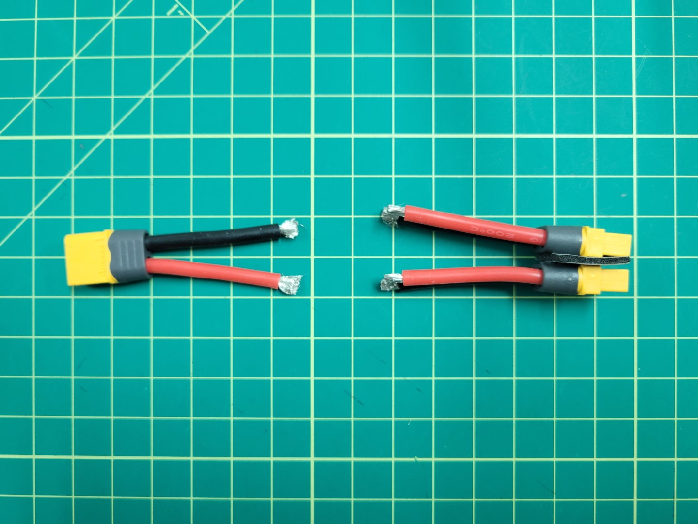
XT60 cables preparation
Next, place heat shrink large enough to slide over the 3 cable solder joint on the side with 1 male connector. Then, solder the 3 ground (black) cables together.
Pull the heat shrink down over the end of the connection and apply heat.
If you have access to a heat gun or a lighter this will work well.
Alternatively, you can use the side of your soldering iron to apply heat and let the tubing shrink over your connectors.
Soldering XT60 cables
Repeat for the voltage (red) cables.
Soldering XT60 cables
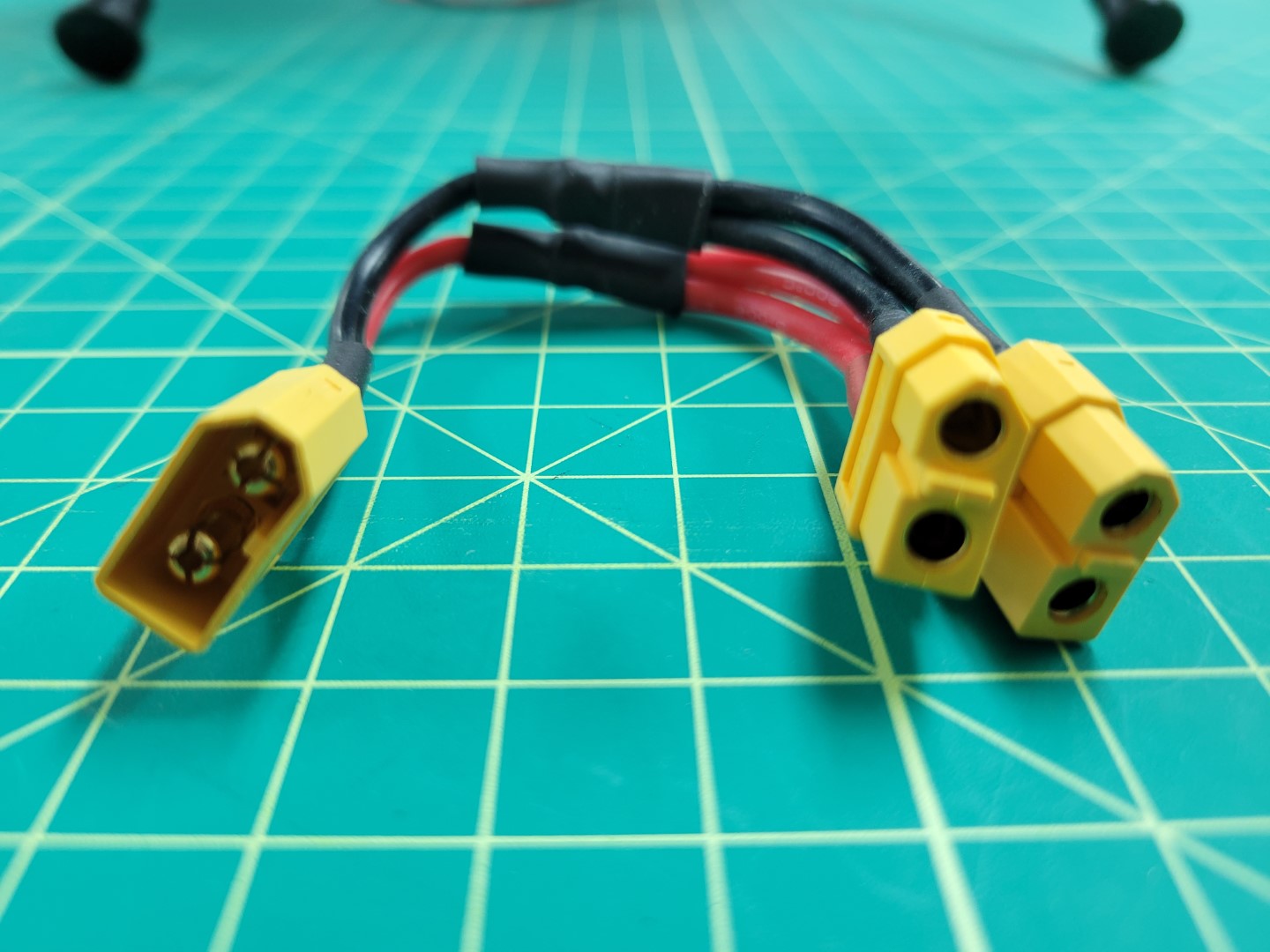
Your finished cable should look like the photo below.
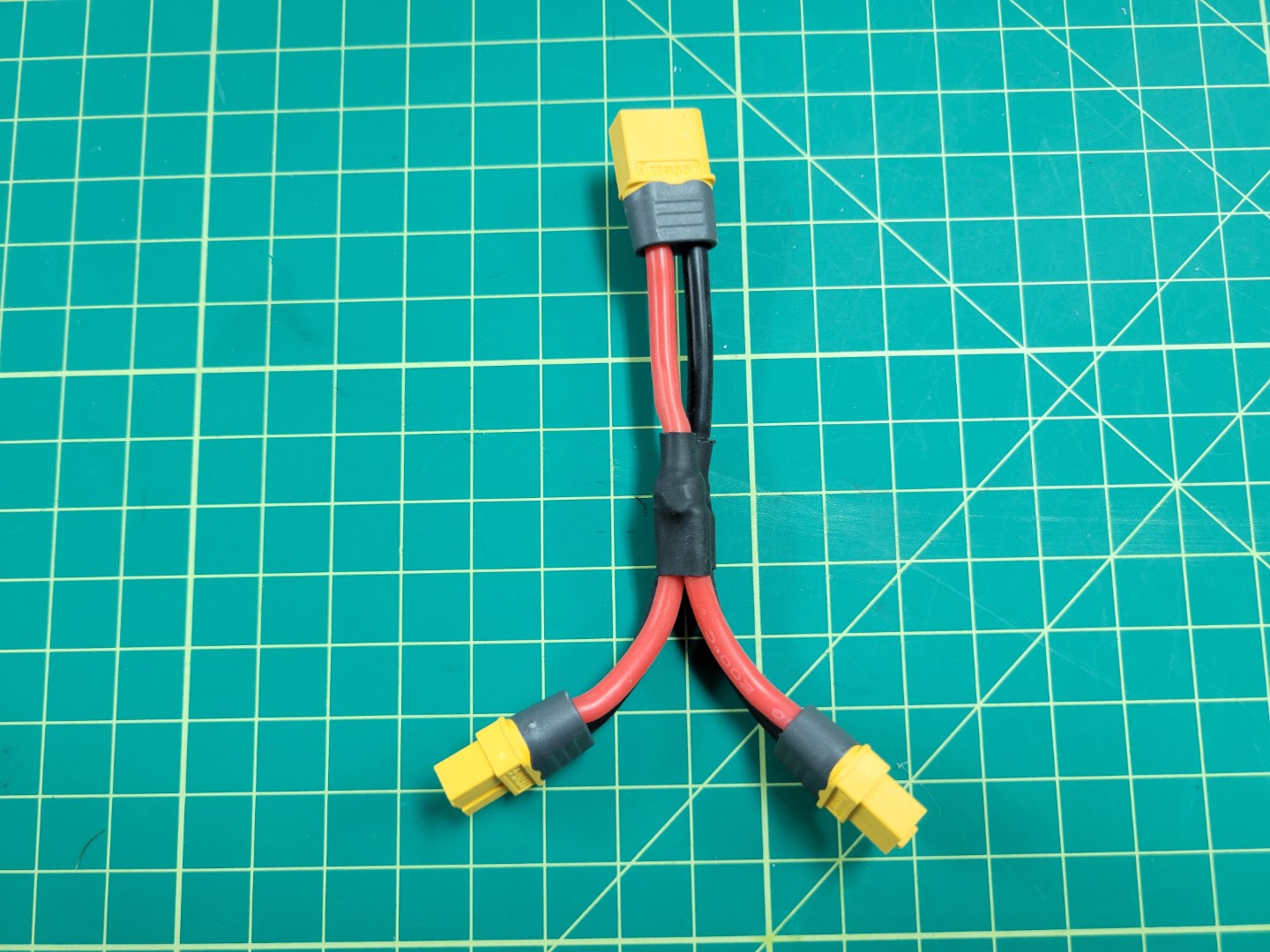
Y cable with 1 male and 2 female connectors
Before installing the buck converters, the Power Distribution Board (PDB) will need to be soldered correctly. The PDB will allow us to split off power from the battery to each of the buck converters.
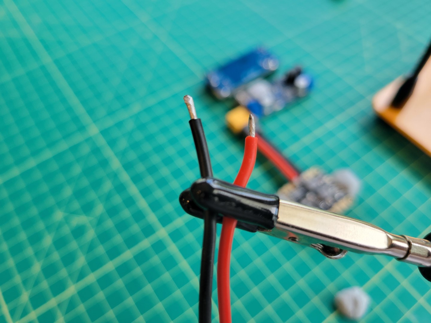
The first step is to solder on the battery leads to the PDB.
To do this cut 1 male XT60 cable to about 2 inches and tin the ends as we did with the y-cable above.
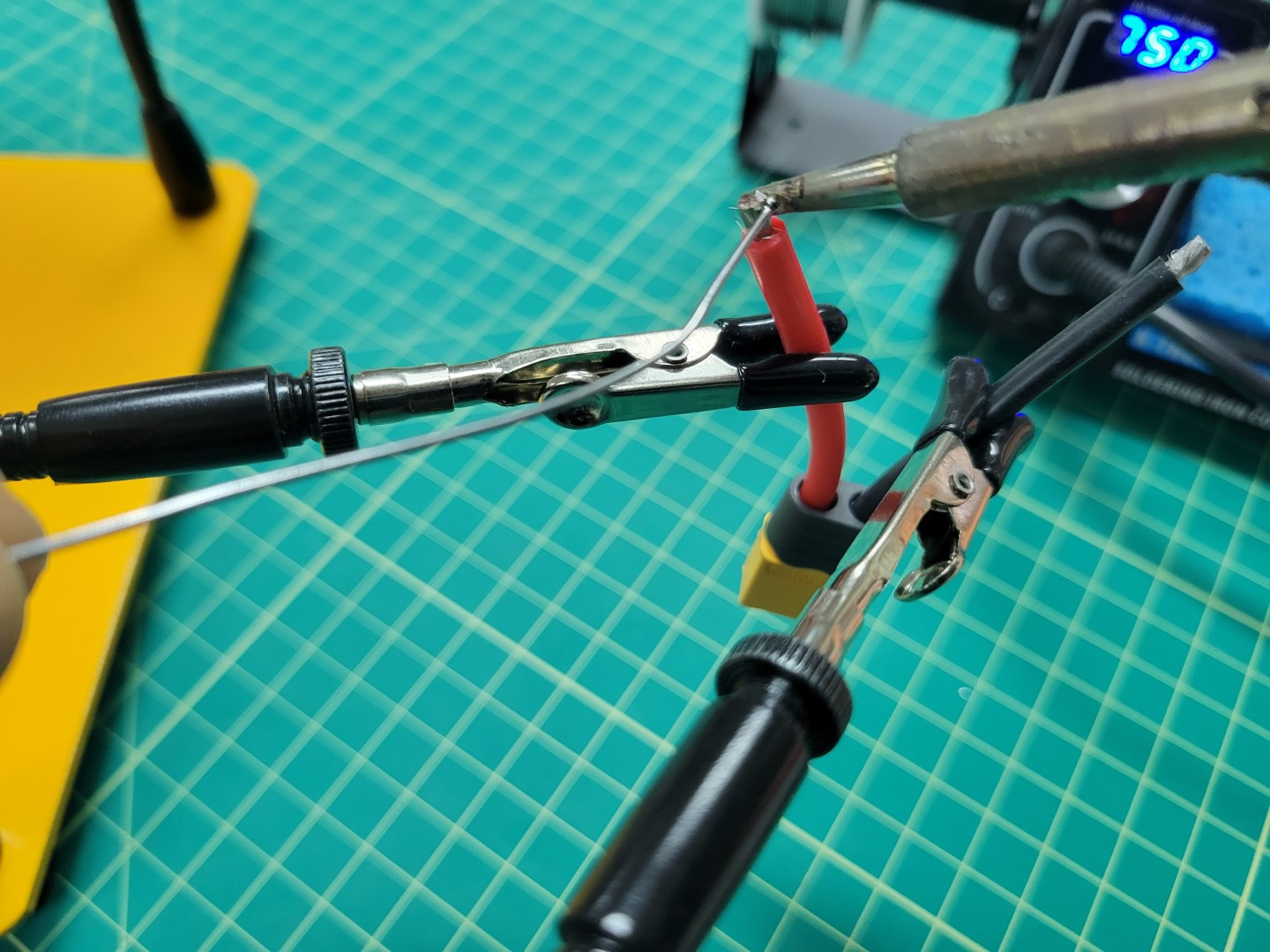
Tinning male XT60 leads
Warning
Soldering the larger pads on the PDB requires skill and patience. If possible, we recommend using a flat tip on your iron instead of the normal pointed tip. This will allow for much better heat transfer.
We recommend watching this video that goes into great detail on soldering. It’s lengthy so at the very least you should scrub through it before attempting to solder the XT60 to the PDB.
You do not want the PDB to slide around while soldering. One of our favorite tricks is to use Blu Tack to hold components in place.
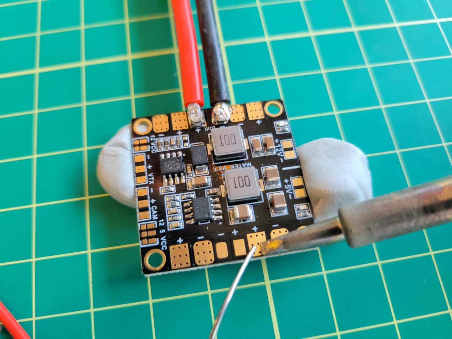
Start the process by tinning the Batt +/- pads as shown in the photos below.
A good temperature to aim for is between 750 and 800 degrees Fahrenheit.
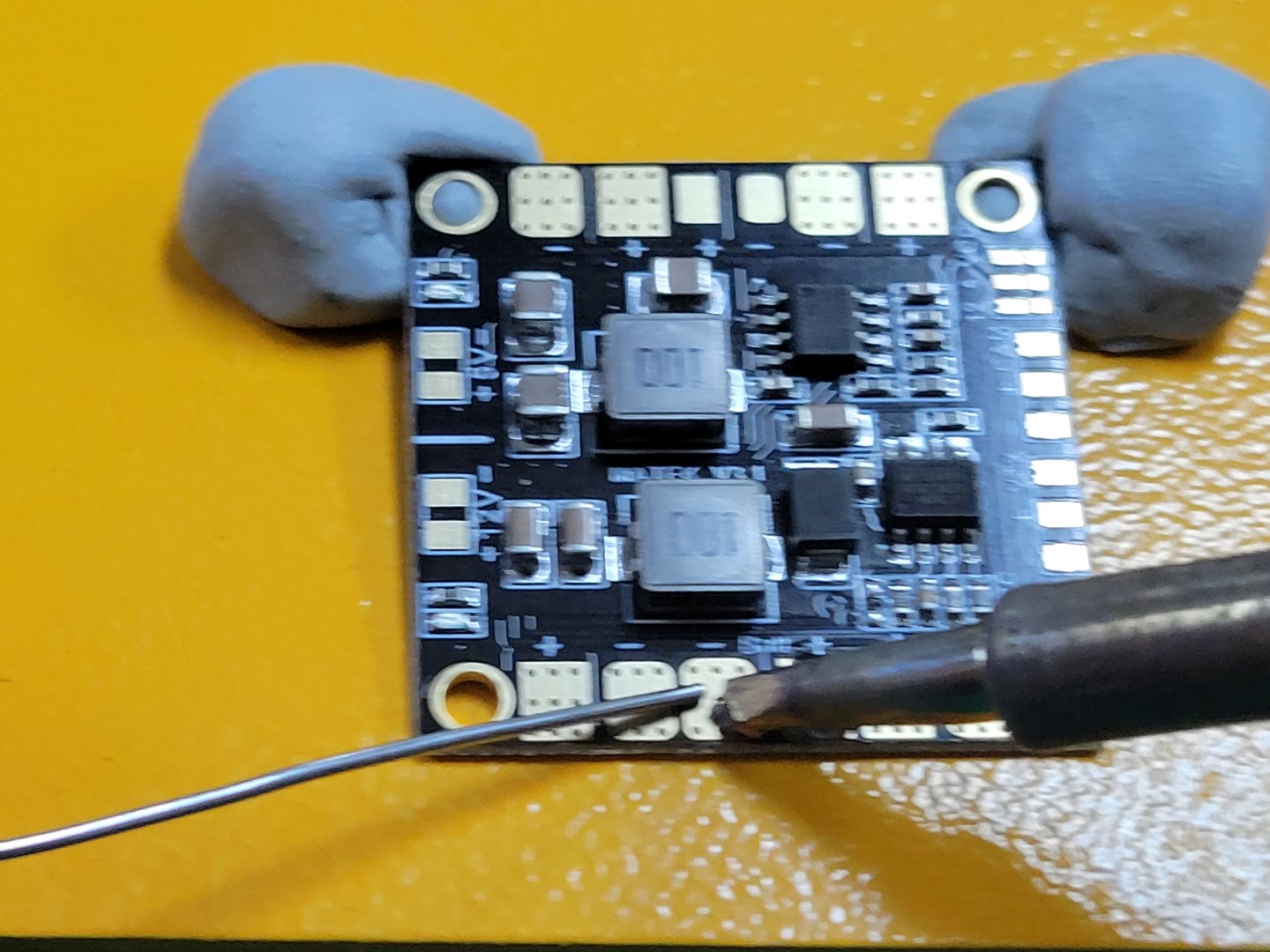
Tinning PDB batt +/- pads
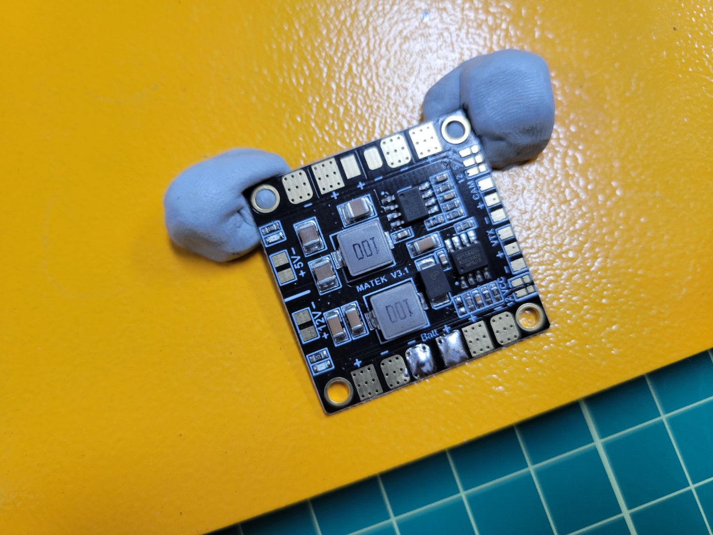
Pads tinned and ready for input wires
Place the positive wire onto the positive pad and set the tip of the iron on top.
Do not apply too much pressure as you do not want the wire to spread out.
The iron should heat both the wire and the pad to form a single solder joint.
Animation of soldering wire to PDB pad
Repeat this process for the negative wire.
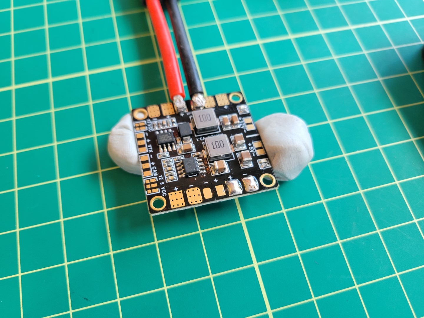
Your completed PDB will look similar to the one below.
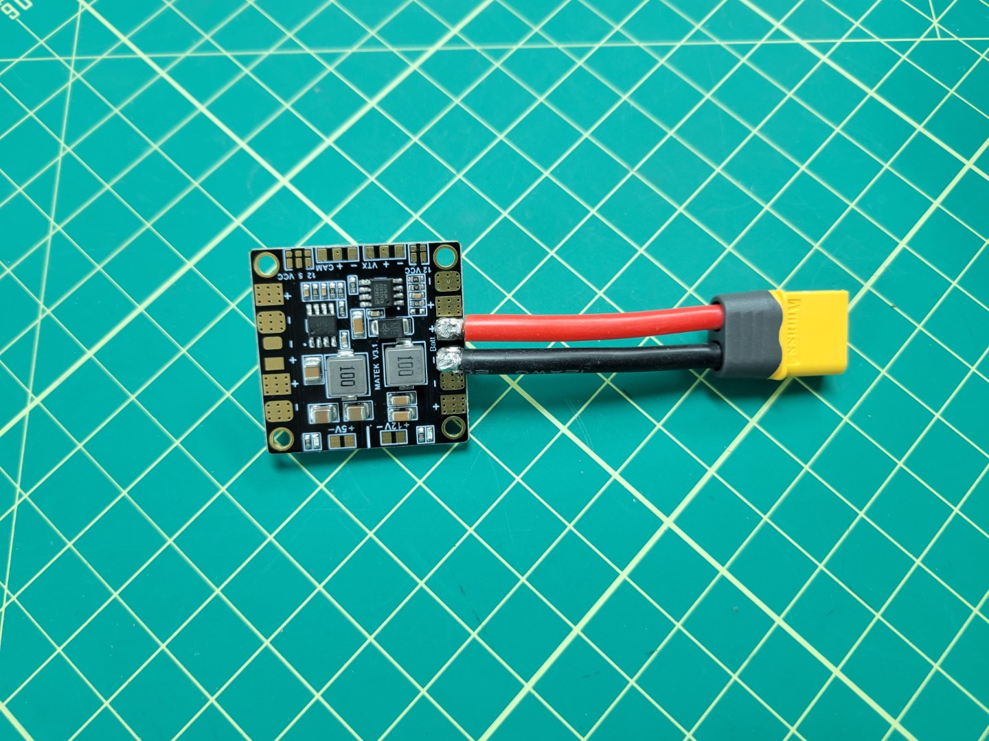
PDB input soldering complete
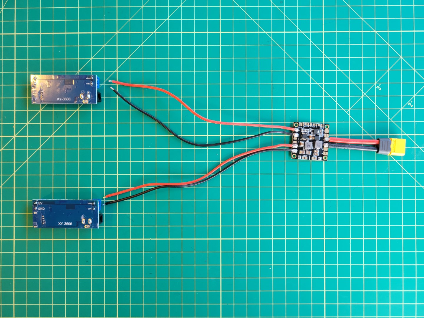
PDB Output Soldering
In the photo below you will notice two identical buck converters,
one for powering the VMC and the other for the PCC.
This section will walk through the necessary wiring to supply power to the buck converters.
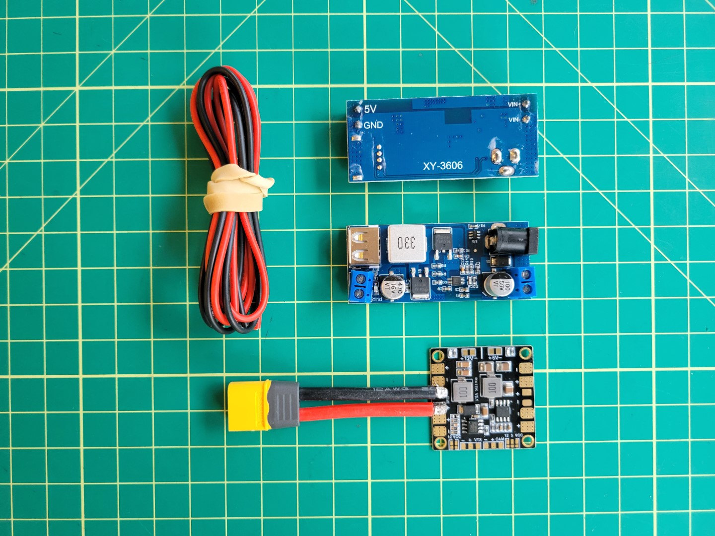
PDB, wires, and buck converters
Cut approximately 8" of wires; 2 black and 2 red.
These will be used to connect each of the buck converters to the PDB.
On the opposite end of the PDB there are two sets of pads that we’ll tin for soldering.
Heat the pad using the tip of the soldering iron and
feed the solder onto the pad as shown in the photo below.
Soldering the PDB
Once the pads are pre-tinned it should like the following.
Pre-tinned Solder Pads
Next, apply solder to the wires to pre-tin them.
Pre-tinned Wires
After pre-tinning everything, place each lead on the corresponding pad and gently push
the soldering iron down.
Like we did with the XT60 connector we want to make sure to apply heat long enough for
the solder on the pad and wire to join.
Soldering wires to pads
Repeat this process for the other two wires.
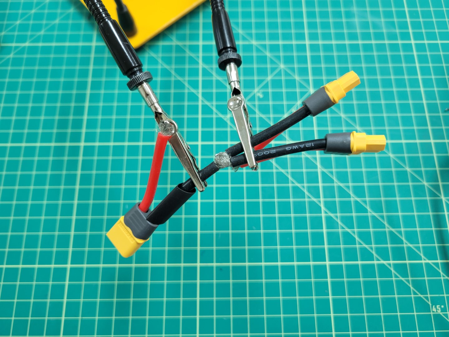
After successfully soldering the positive and negative wires to the PDB,
use a multimeter to run a continuity test.
This will ensure that there are no shorts between the positive and negative terminals.
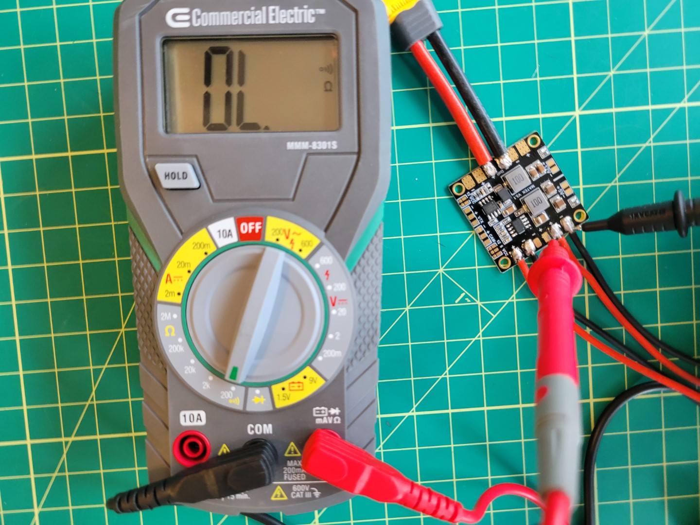
Checking connections
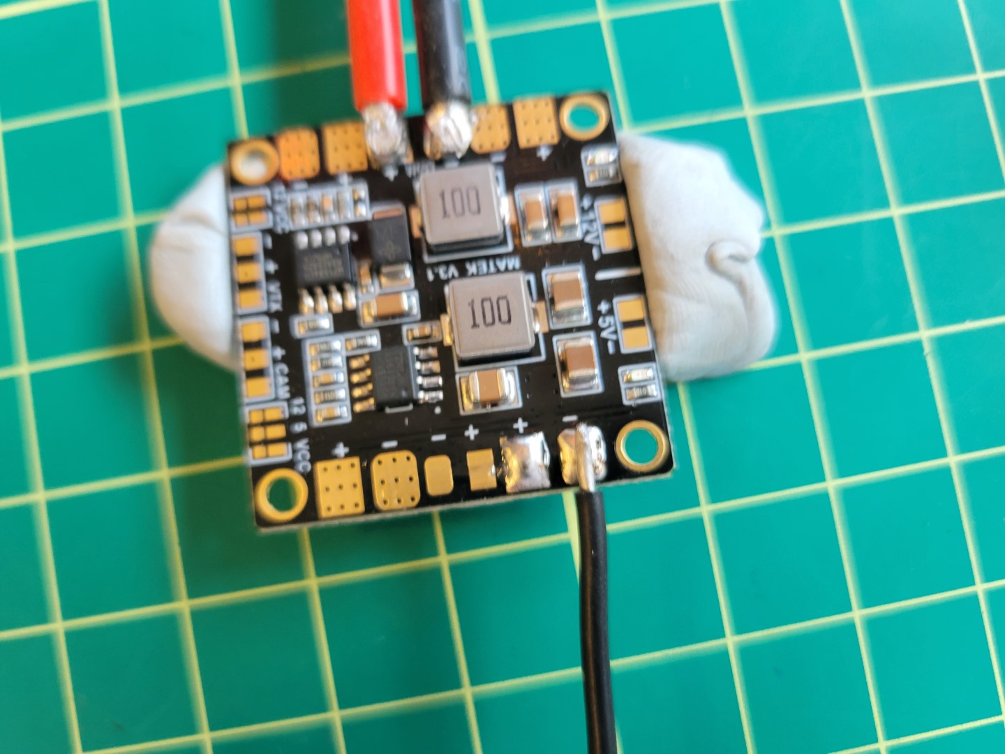
You should now be at a place where you have the PDB soldered as shown in the following photo.
Power Distribution Layout
Finally, place the PDB on top of the ESC standoffs and secure using M2.5 nuts from your AVR kit.
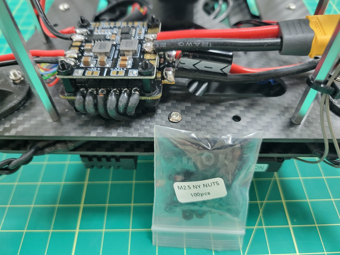
Mounting the PDB
2 - Buck Converter Mounting
Overview
Wire management is an important part of any drone build.
It will make your build easier to maintain, look professional, and keep wires from potentially getting caught in your drone’s propellers.
In the previous section we pre-soldered the VMC/PCC power wires and mounted the PDB.
Now we will focus on wiring and mounting the buck converters.
The power wires from the PDB will be run through the mid-plate assembly to the front of the AVR drone.
This is necessary to make sure the wires do not interfere with battery mounting, which we’ll cover in an upcoming section.
Note
A quick reminder that we try to supply you with best practices for your drone assembly.
In some cases you may chose to venture out and find a better way to accomplish a task.
That’s completely fine and you’re highly encouraged to do so!
We even encourage you to share a given solution in
our forums.
Wiring
The PDB and ESC are both mounted near the right rear of the frame.
The buck converters will be mounted near the front of the frame.
This means we need to run the cables up through the mid-plate assembly and drop them down in the front of the frame.
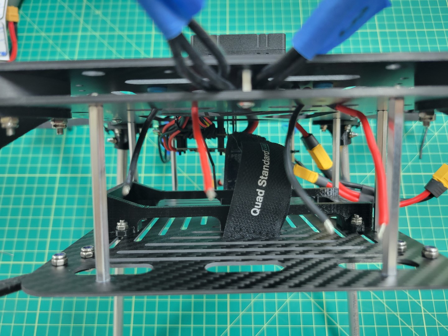
Feed the wires into the mid-plate assembly and zip tie them to the mid-bottom plate as shown in the photo below.
Securing these wires is important as you don’t want them to interfere with battery mounting.
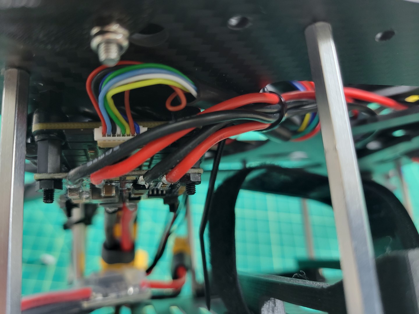
VMC and PCC power leads run through mid-plate assembly
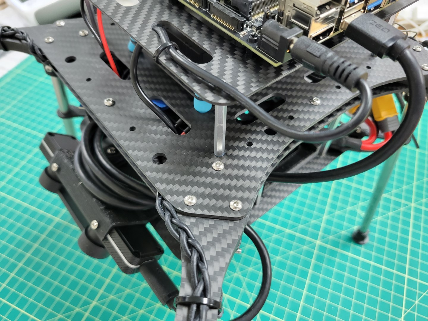
Drop the wires down through the two large oval cutouts in the mid-bottom plate as shown in the photo below.
Tip
It is much easier to feed the wires through the mid plate assembly by temporarily pulling
your excess motor/ESC wire out of the frame to free up space.
Be sure not to accidentally disconnect them!
VMC and power leads ready to connect to buck converters
Mounting
We will mount the buck converters using the 3M double-sided tape provided in your AVR kit.
The solder joints on the bottom of the buck converters stick out a good bit so we will double-stack tape on each end.
The reason for this is that we do not want to the solder joints to accidentally make contact with the carbon fiber plate.
This could lead to a short circuit. Cut one of the 3M squares into four pieces as shown in the photo below.
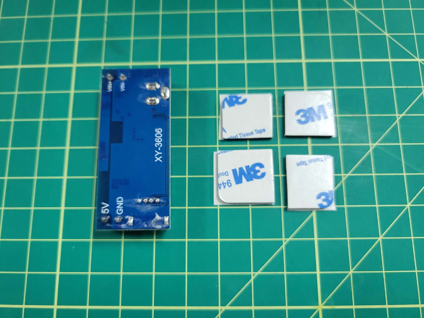
3m tape cut into four squares
Double stack the tape on each end of the buck converter as shown in the photo below.
Repeat the process for the other buck converter.
Double stacked 3M tape on buck converter
Before securing the buck converters to the AVR frame we will connect the input leads to the screw terminals on each buck converter as shown below.
Warning
Make sure you are connecting the input power leads to the terminals labeled VIN+ and VIN- on the buck converter.
These are located next to the barrel jack.
Tip
You want to tightly screw down on the wires otherwise they may come loose.
If you find the wires are coming loose you can always remove them, tin them with solder, and try screwing down on them again.
Power wires connected to buck converter terminals
Take the remaining 18 gauge wire (the wire you used to supply input power from the PDB to each buck converter) and connect it to the output terminals on the PCC buck converter.
The PCC buck converter will be on the left side as drone is facing you.
You can see the output wires on the left side of the photo below.
PCC buck converter with output wires on left and input wires on right
VMC power is supplied with a barrel plug. Find the cable with the barrel plug in your kit and cut it to 8".
Remove the shielding and expose about 1/8" from the positive and negative wires as shown in the photo below.
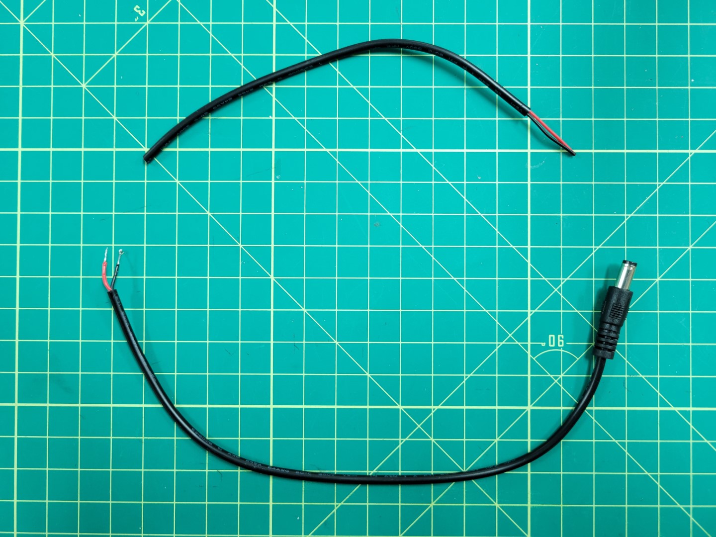
Prepping power cable for VMC
Connect the positive and negative leads to the output terminals on the VMC buck converter.
Once again, screw down tightly on the terminals so that the wires do not come loose.
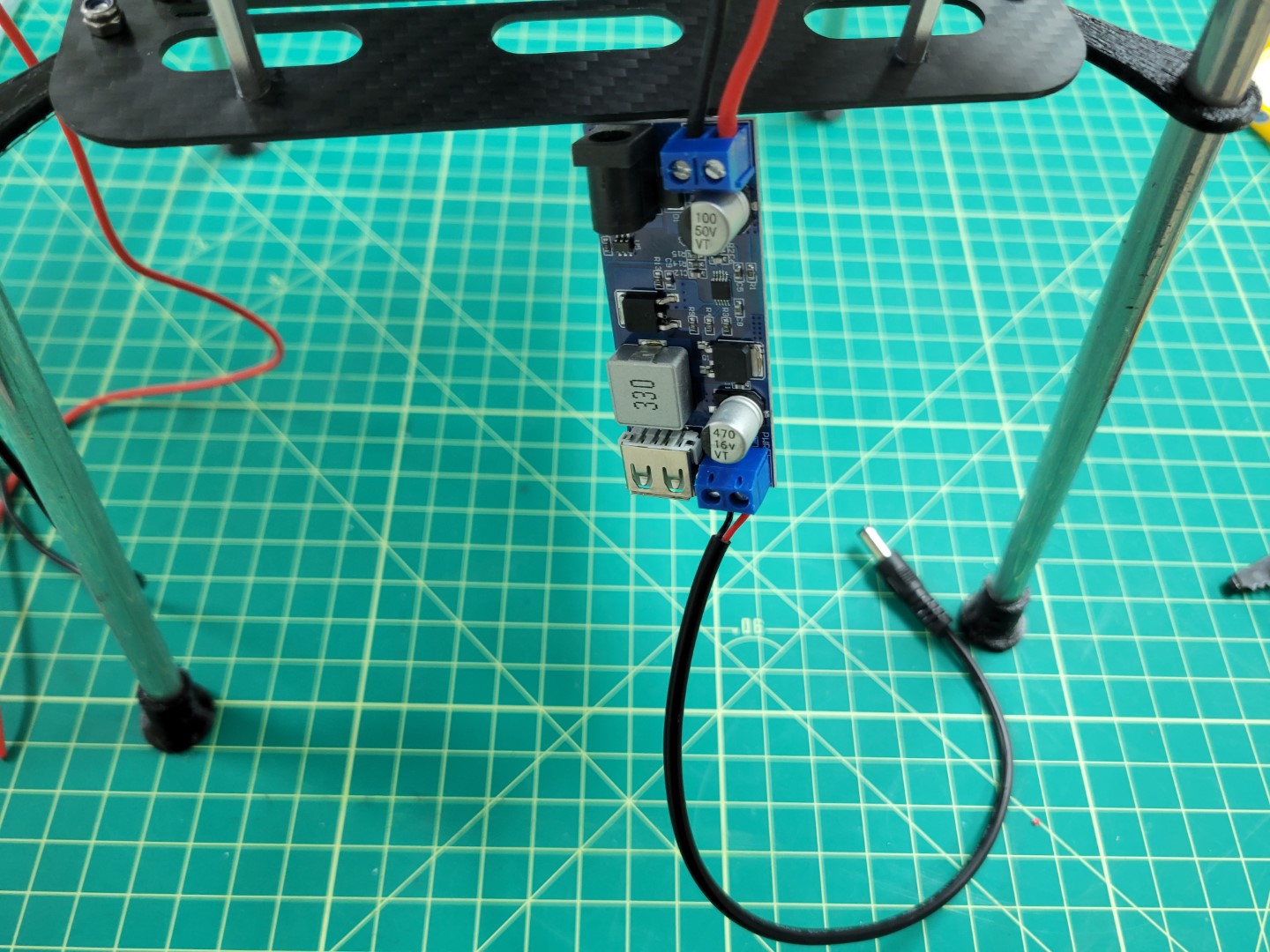
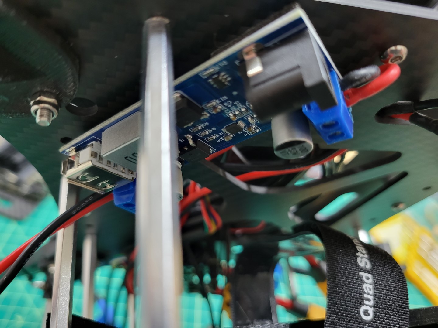
VMC buck converter wired up with barrel plug
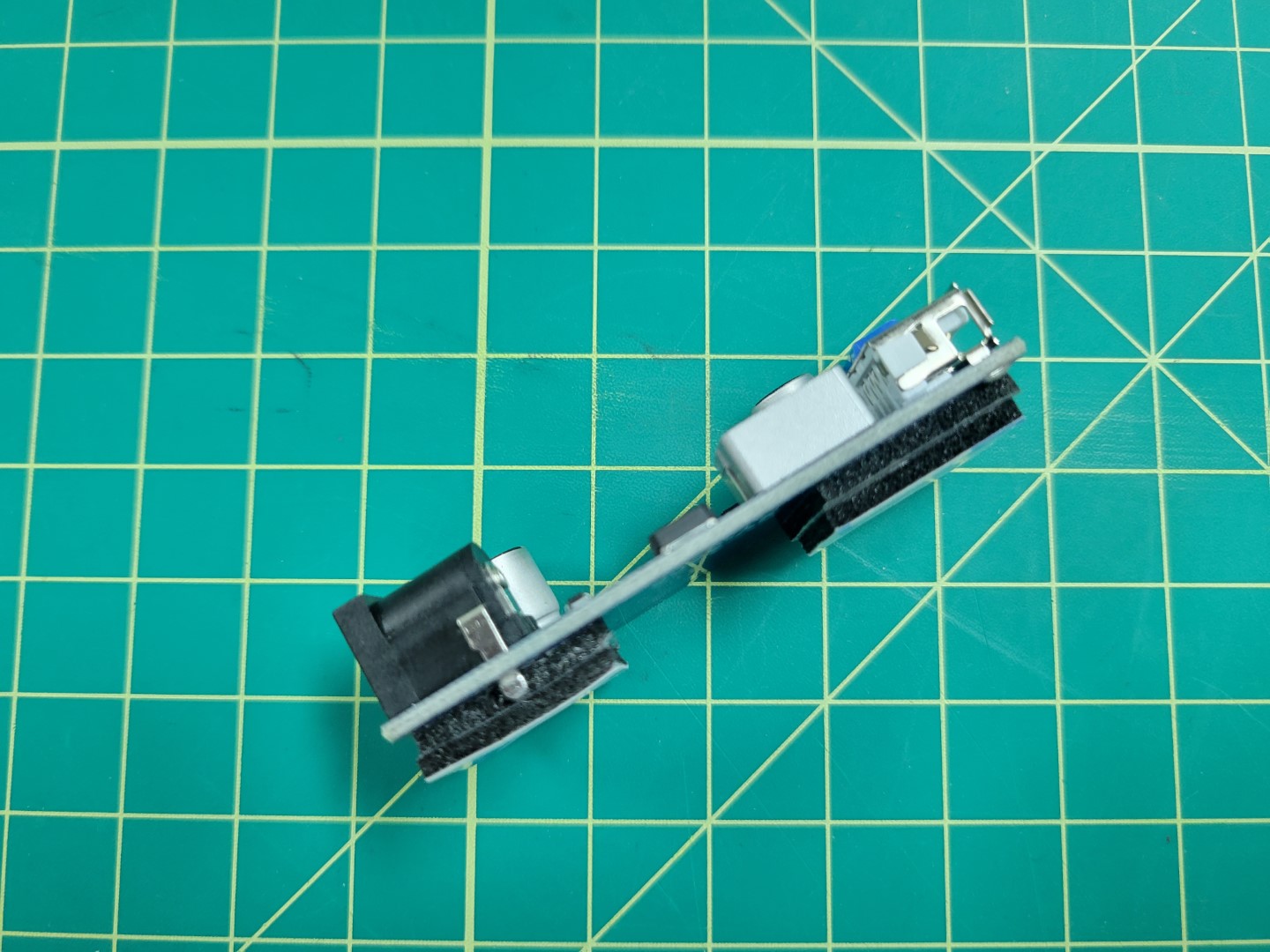
Stick the PCC buck converter on the left side of the bottom mid-plate and the VMC buck converter on the right (as the front of the drone is facing you).
Place each buck converter at a 45 degree angle with the output leads pointed towards each side of the frame.
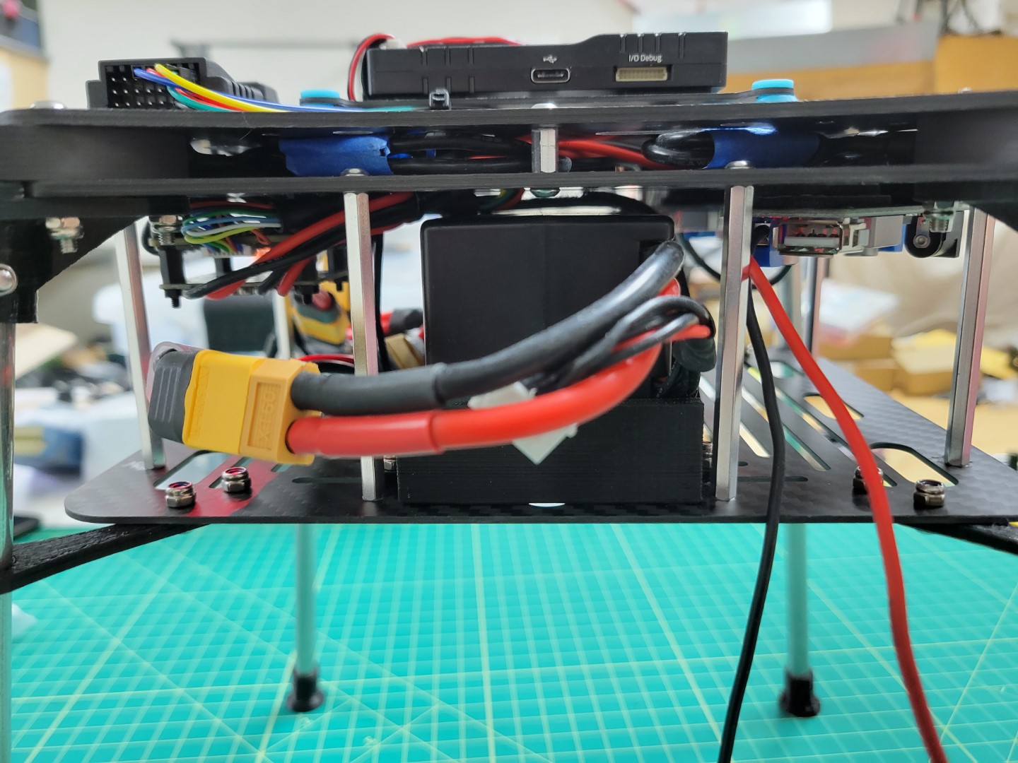
The photo below shows the PCC leads on the left side of the frame and the VMC barrel plug on the right.
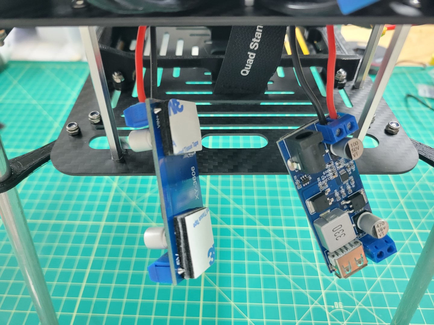
Note
Make note of the yellow circles in the photo below. These are the access holes for mounting the standoffs for the top accessory plate.
Be sure not to cover these holes when mounting the buck converters.
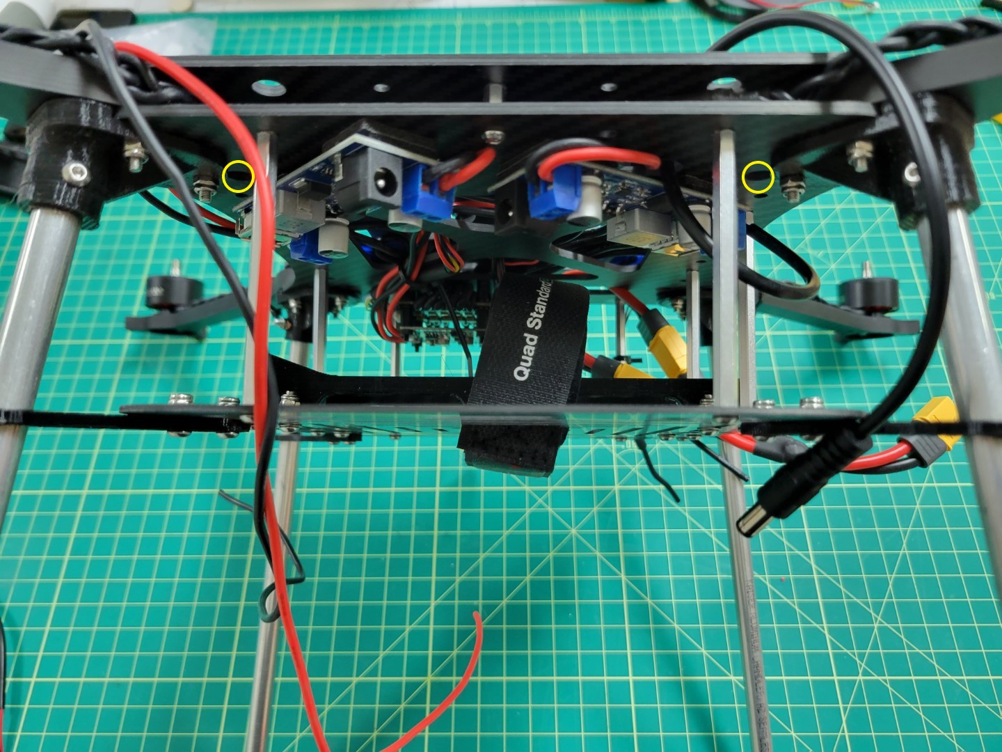
Buck converters mounted at 45 degree angle
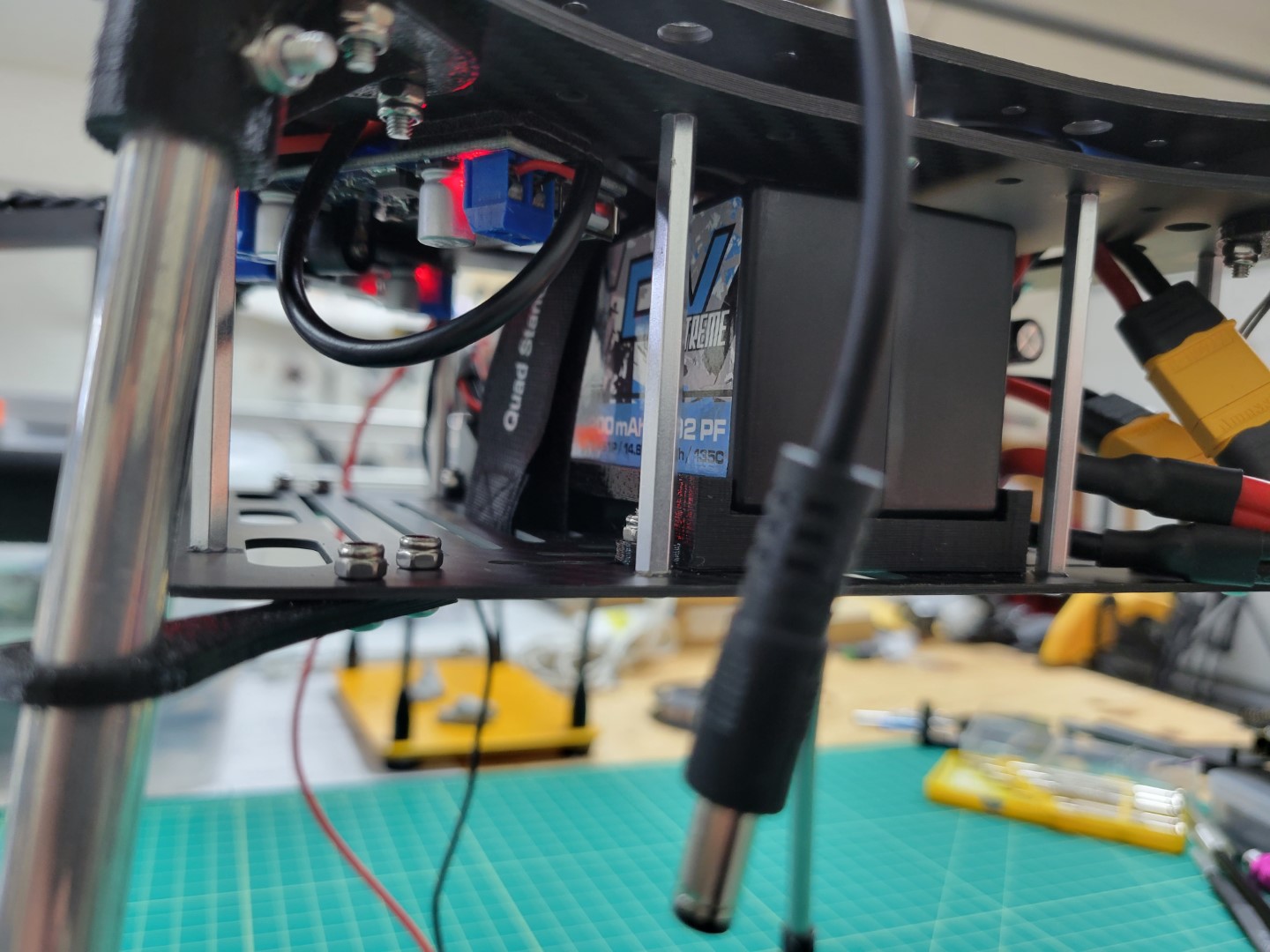
The photo below shows the right side of the frame and clearance for the battery to slide into the tray.
The PCC will be mounted and powered from this side of the frame.
Right side battery clearance
The photo below shows the left side of the frame where the battery can slide into place without any obstruction from the buck converters.
The barrel plug hangs off this side of the frame and will be used to power the VMC.
Left side battery clearance
Take a quick look at the wiring orientation from a top down perspective.
In the next section we will build the top plate assembly and install it over the FC.
Top down view of power wires for VMC and PCC
3 - FC ⟷ VMC Telemetry Cable
Overview
It’s important that the FC and VMC can communicate with each other.
This bi-directional communication will allow us to receive telemetry
data from the FC and send data to it from the VMC. If you recall,
before we communicated with the FC using a micro-USB cable connected to a
PC running QGroundControl. What you will be able to do now is communicate over a
WiFi network, which will make this process easier.
In addition to a wireless link between the AVR drone and QGC you will learn
how to configure position hold capabilities using external cameras. You may
have noticed with the basic drone that the drone required constant input from the
pilot to maintain position in stabilized flight mode. With the assistance
of these cameras you will be able to hover in position mode with ease!
The cable we build in this section makes this all possible.
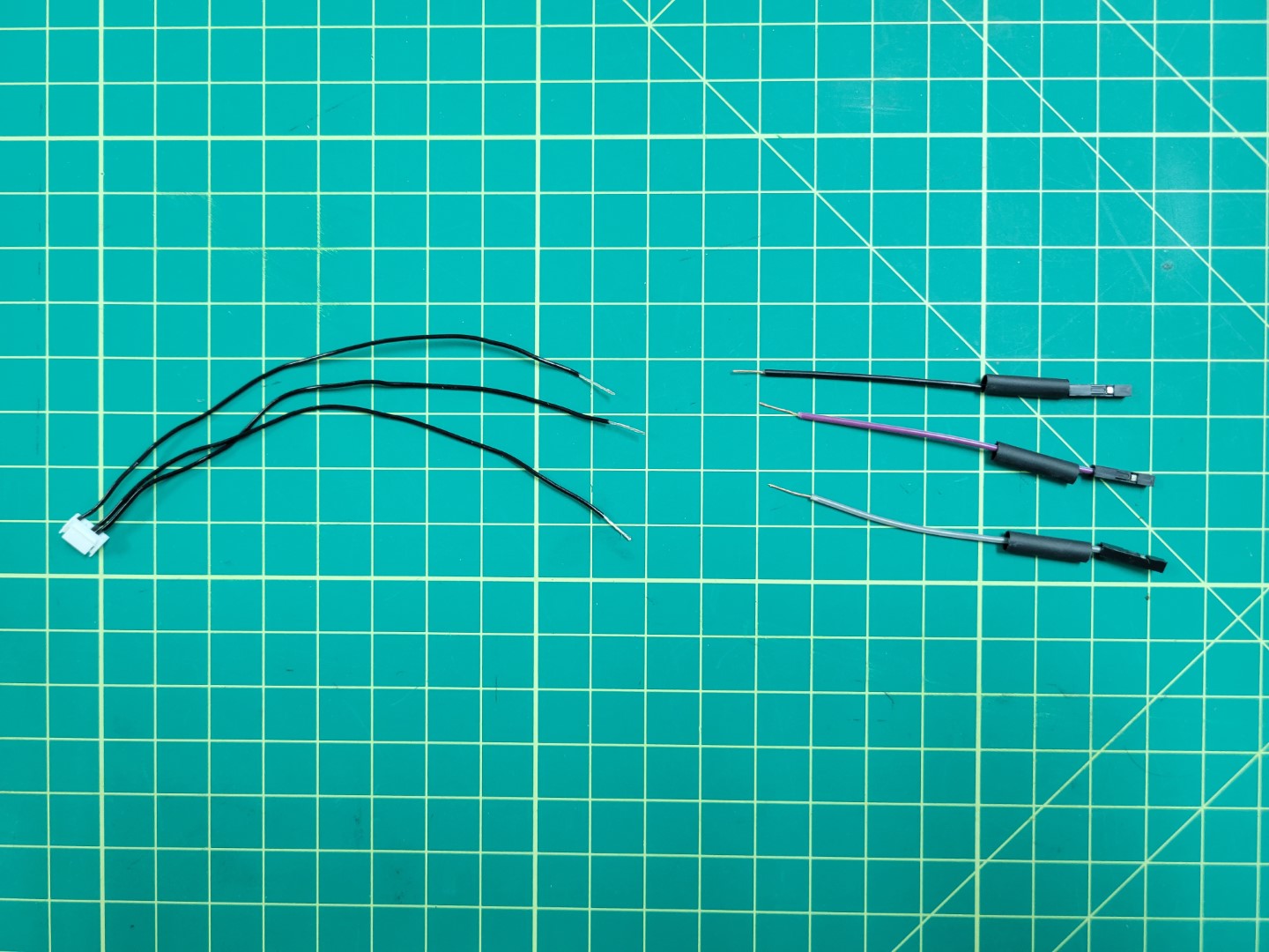
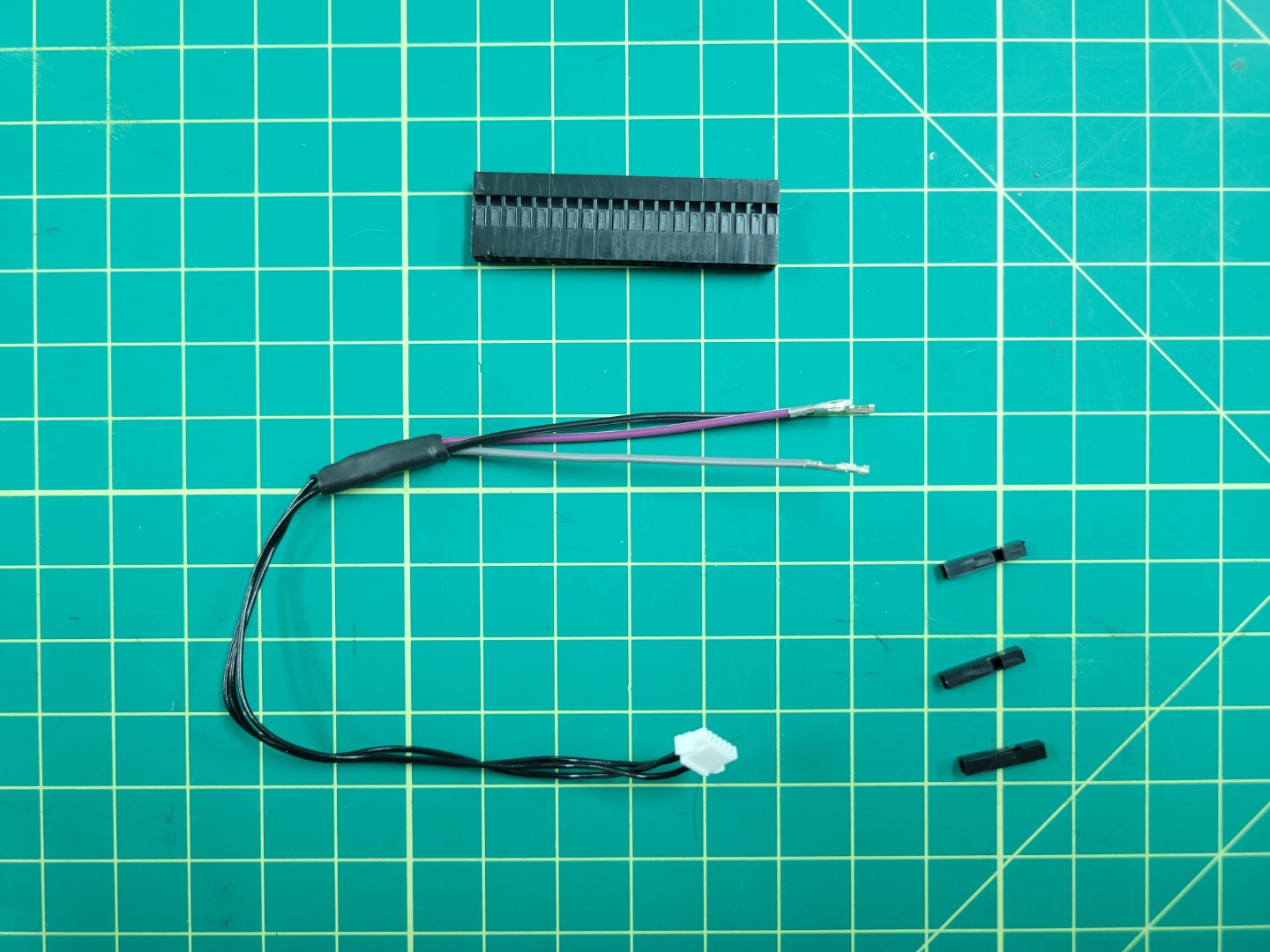
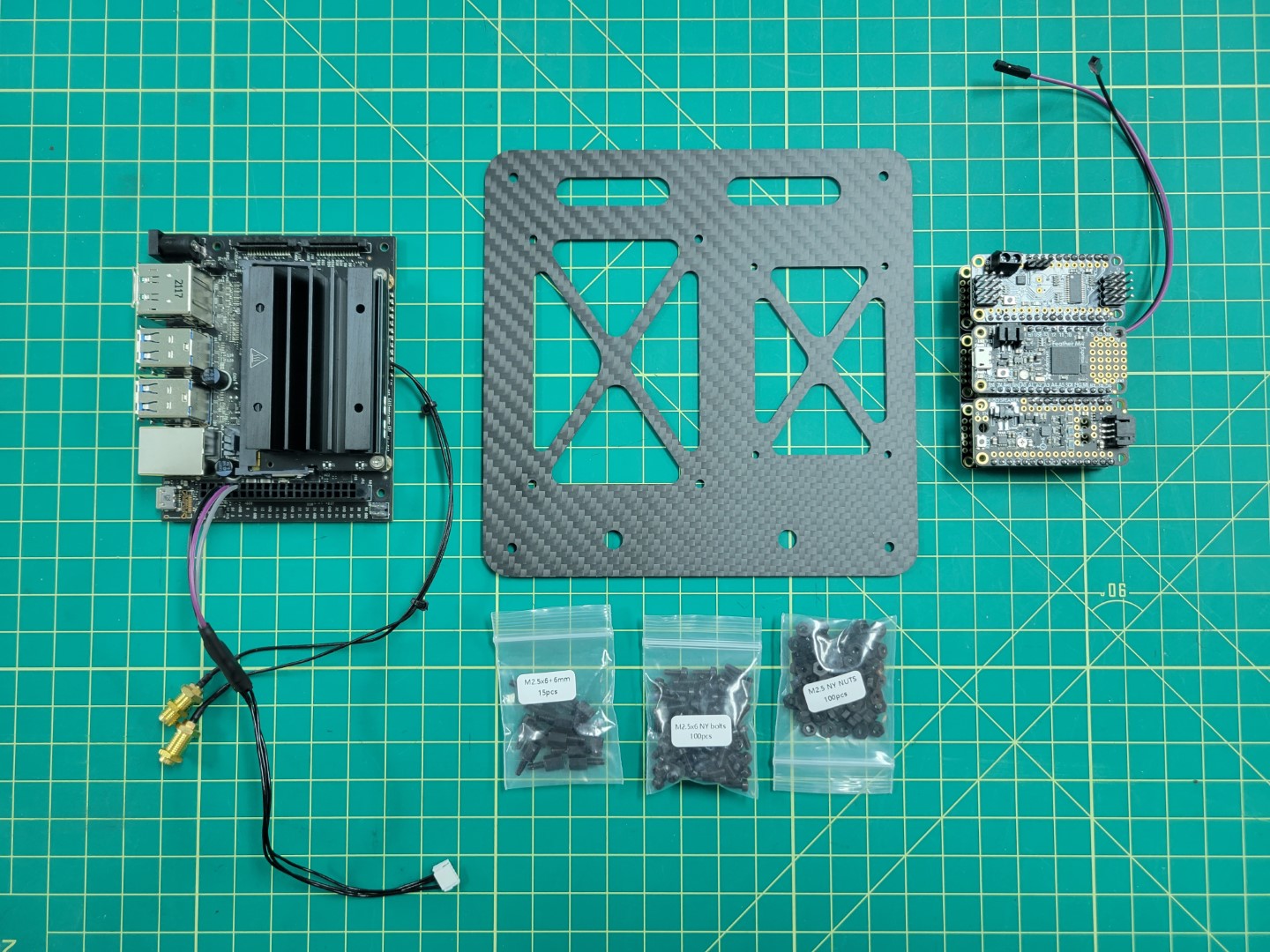
Locate the following components in the photo below:
- 6 pin cable from the Pixhawk box
- 40 pin connector housing
- 3 female to female wires (black, purple, and grey)
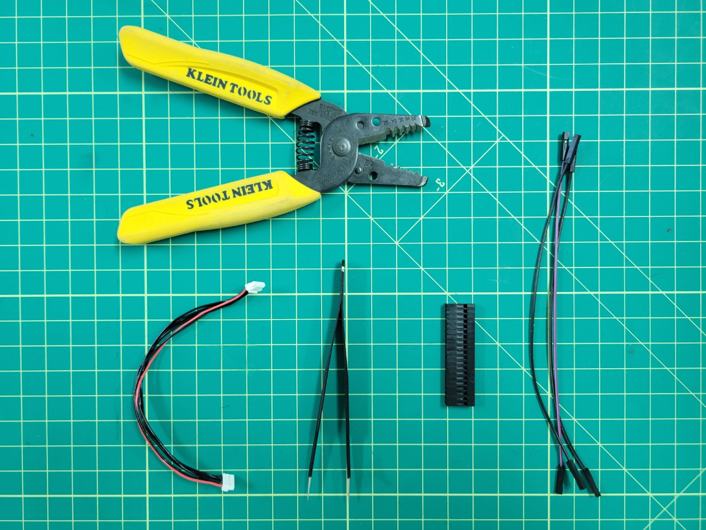
Necessary components for telemetry cable
Creating the Cable
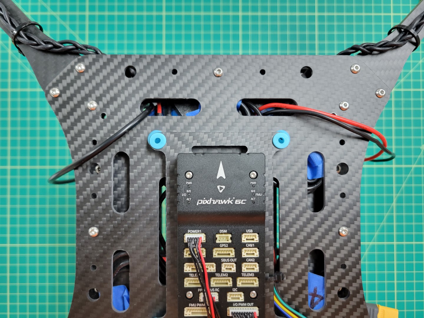
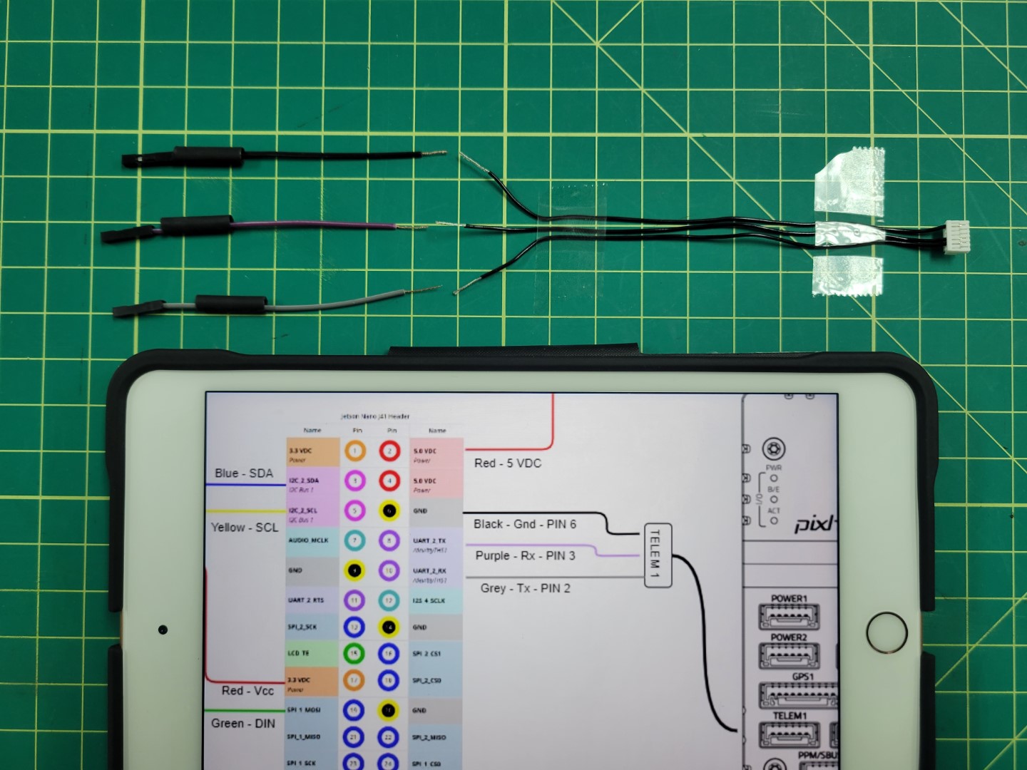
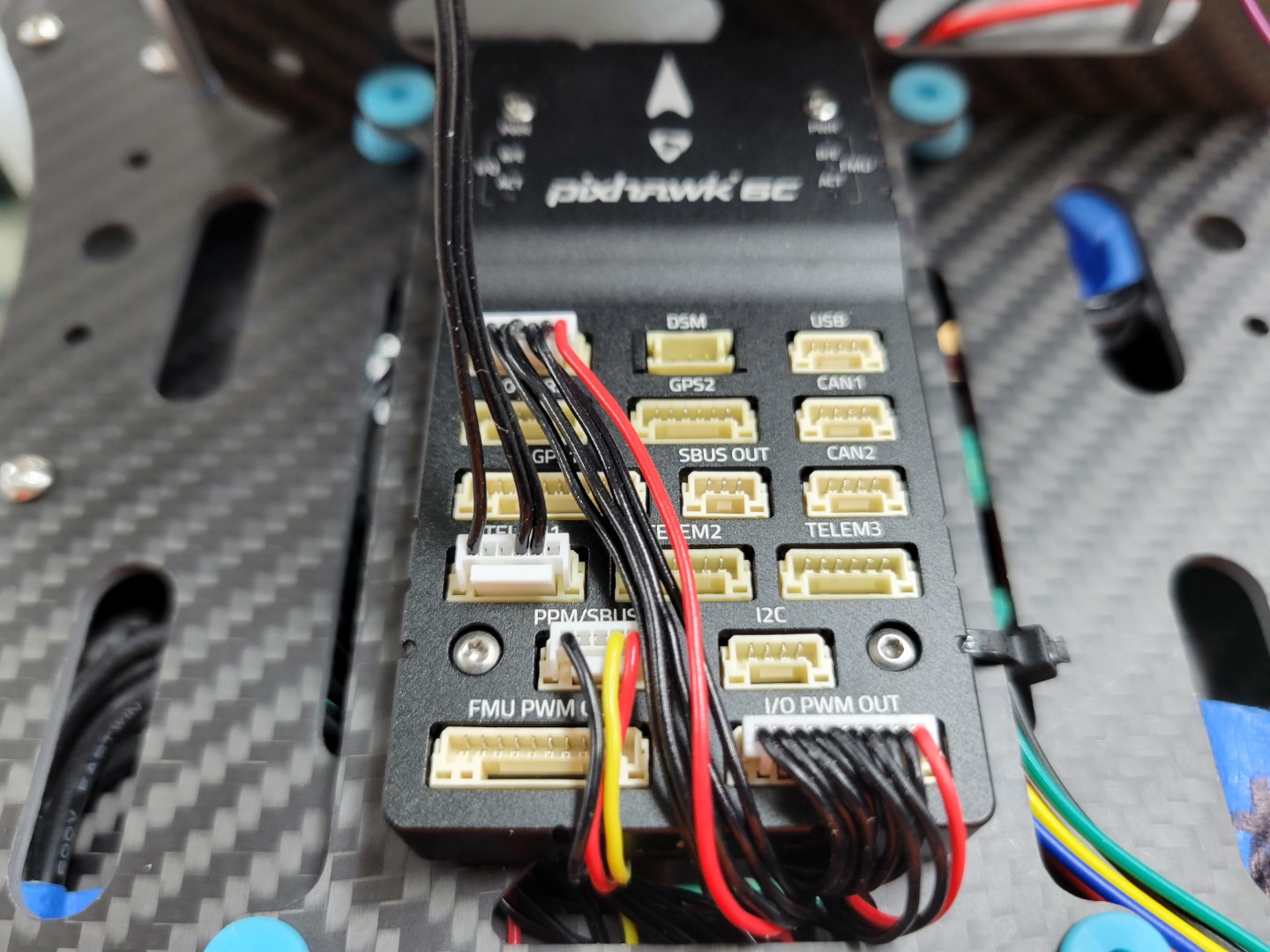
Before we start building the telemetry cable let’s take a quick look at the following wiring diagram. The middle area represents the 40 pin connector housing. Pay attention to the pinout from the connector housing to the TELEM1 port on the Pixhawk FC. We will be using the following pins:
- Pin 2 - TX - Grey
- Pin 3 - RX - Purple
- Pin 6 - GND - Black
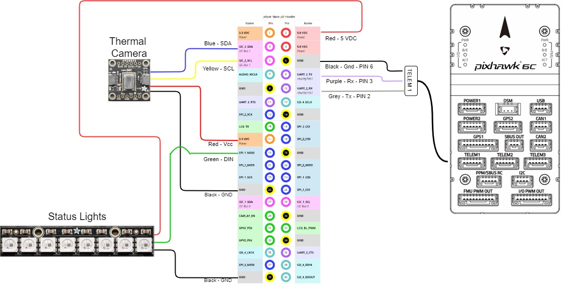
VMC pinout
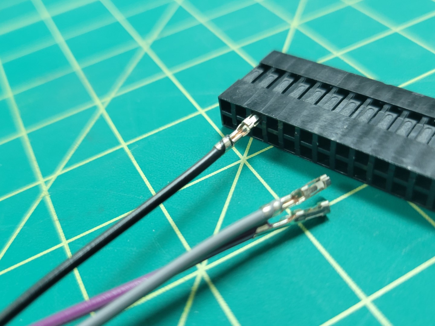
Using tweezers you will remove pins 1, 4, and 5 from the Pixhawk connector. This is done by prying the plastic tab for each pin as shown in the photo below.
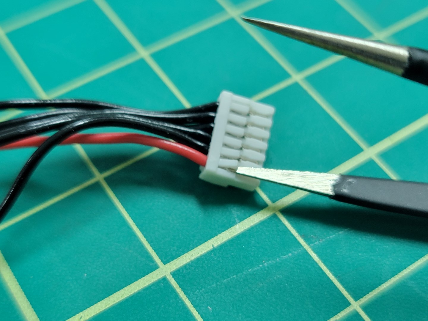
Removing pin 1 from the telemetry connector
The photo below shows only the necessary pins remaining: pin 2, 3, and 6 from left to right.
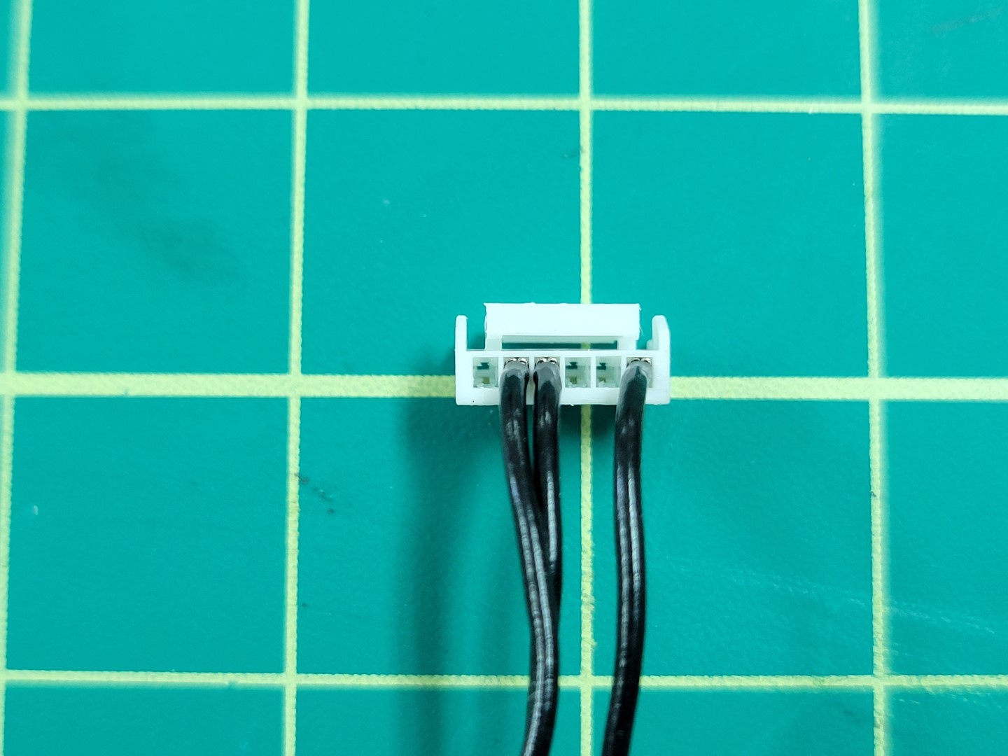
Telemetry wires: TX, RX, and GND
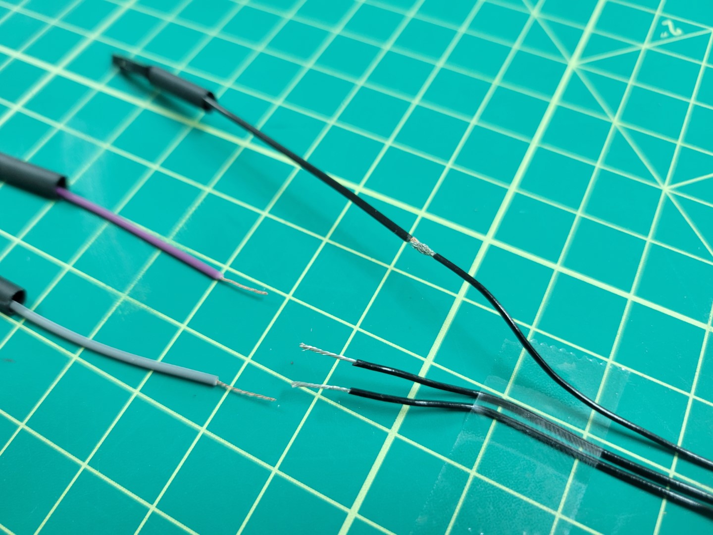
Clip the connector from the other end of the Pixhawk cable. Cut all three of the individual female-female wires to approximately 2-3". Strip 1/2" of shielding away from all wires as shown in the photo below.
Wire prep for soldering
Prior to soldering make sure each colored wire matches the corresponding pin. The photo below shows one final check before soldering.
Confirming layout before soldering
Join the wires using the “Twisted Helix” method we covered in the ESC wiring during basic assembly.
Joining wires prior to soldering
Solder all three wires and apply heat shrink.
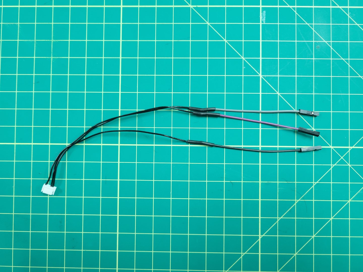
Telemetry cable with all three wires soldered
Remove the plastic connectors from the grey, purple, and black wires.
Plastic connectors removed
Insert all three wires into the 40 pin connector housing as shown in the following photos. If you’re uncertain where to insert the wires refer back to the diagram in the overview section.
Make sure you hear each of the pins click into the connector housing. Inserting them properly into the housing will prevent them from accidentally getting pulled out.
Adding telemetry wires to 40 pin connector
Now that your telemetry cable is complete you can do a test fit. Pay attention to the orientation of the 40 pin connector as seen in the photo below.
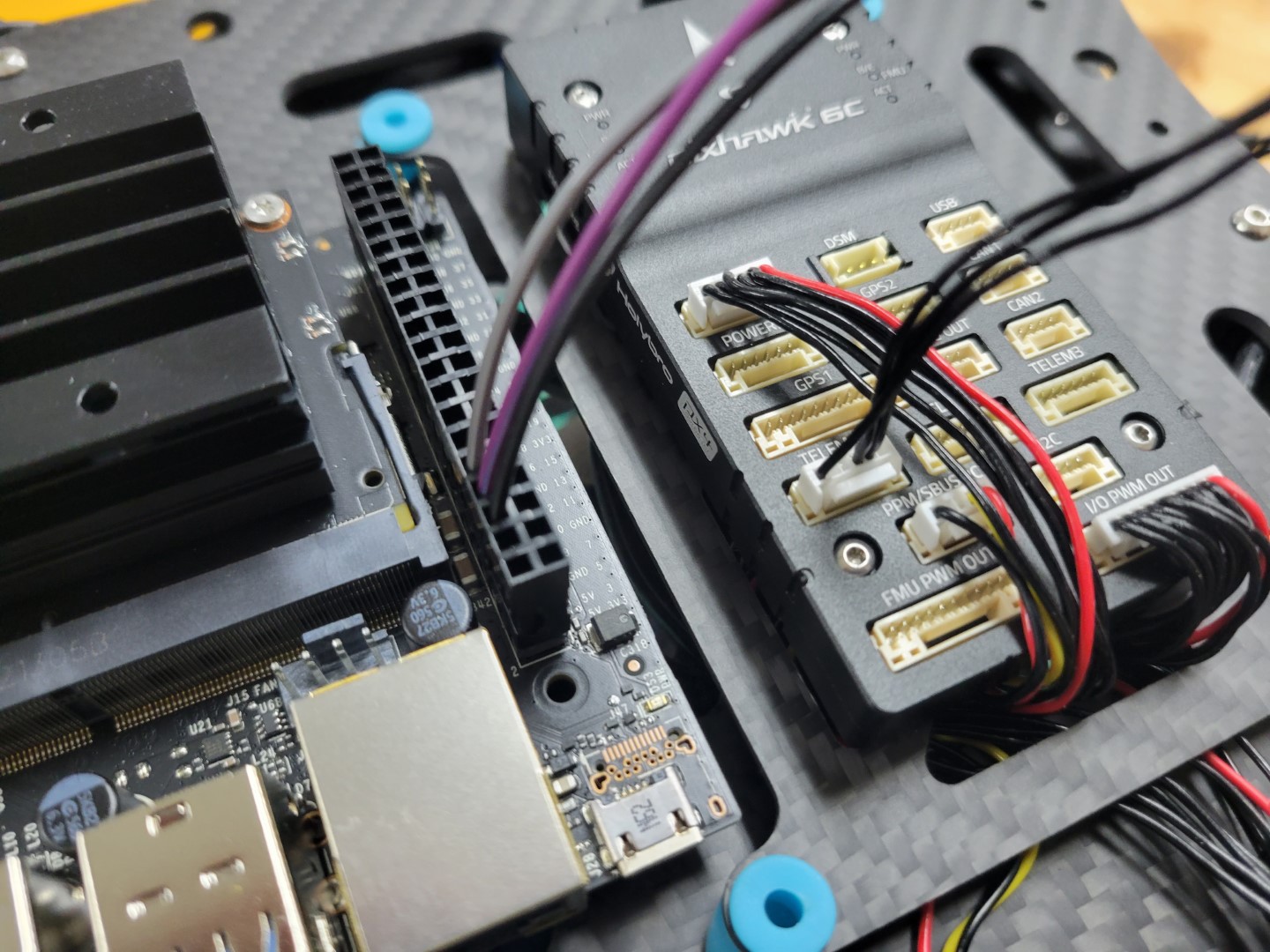
Telemetry cable connected to VMC and Pixhawk TELEM1 port
4 - Top Accessory Plate Assembly
Overview
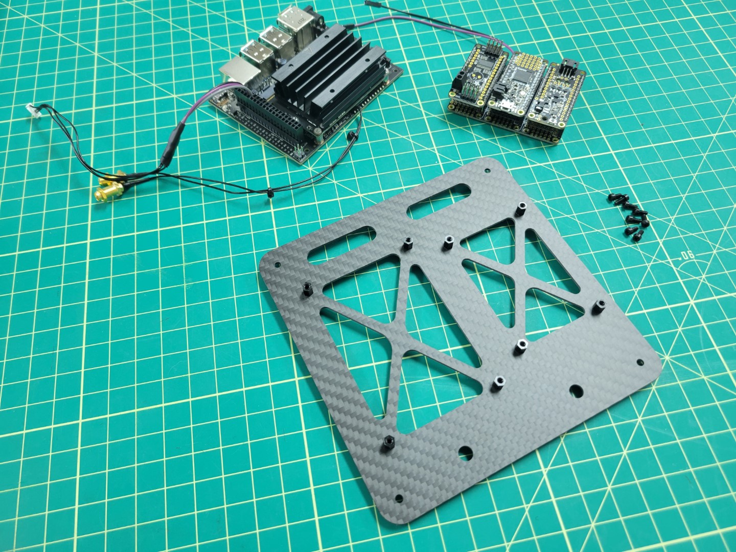
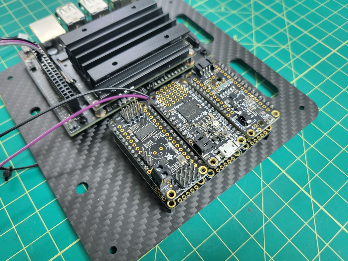
In this section we will cover mounting the VMC and PCC to the top accessory plate followed by attaching the plate over the FC. Locate the ziploc bag of 2.5mm nylon hardware. We will be using the 6mm nylon standoffs, bolts, and nuts. Make note of the four holes around the larger cutout on the left. This is where we will mount the VMC. In addition, make note of the four holes around the smaller cutout on the right. This is where we will mount the PCC.
VMC, PCC, top assembly plate, and nylon hardware
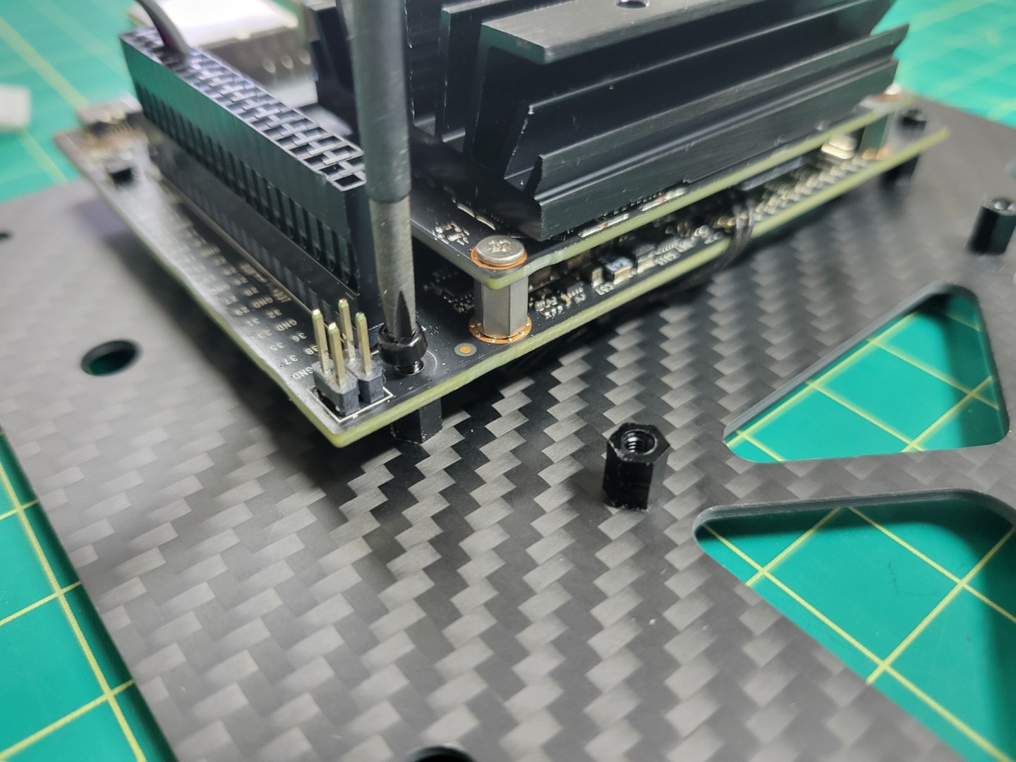
Start by placing the 6mm standoffs facing down through the mounting holes in the top plate. Use a 2.5mm nut to secure each of the standoffs.
Installing 6mm standoffs
The photo below shows the completed standoff installation.
6mm standoffs in place for VMC and PCC mounting
VMC Mounting
We will now mount the VMC to the top accessory plate. The VMC is the “brains” behind your AVR drone build and will be responsible for running the Bell software stack during testing and on competition day.
With the standoffs secured into the top accessory plate the next step is to attach the VMC. These standoffs will provide enough clearance for the VMC so that the solder joints beneath do not make contact with the carbon fiber plate. Carbon fiber is conductive, which means that it can cause your board to short out if two leads touch the plate.
Align all four of the VMC mounting holes over the 6mm standoffs and secure into place with the nylon bolts. The VMC will be mounted on the left of the top accessory plate with the USB ports facing out.
Securing nylon bolts for VMC mounting
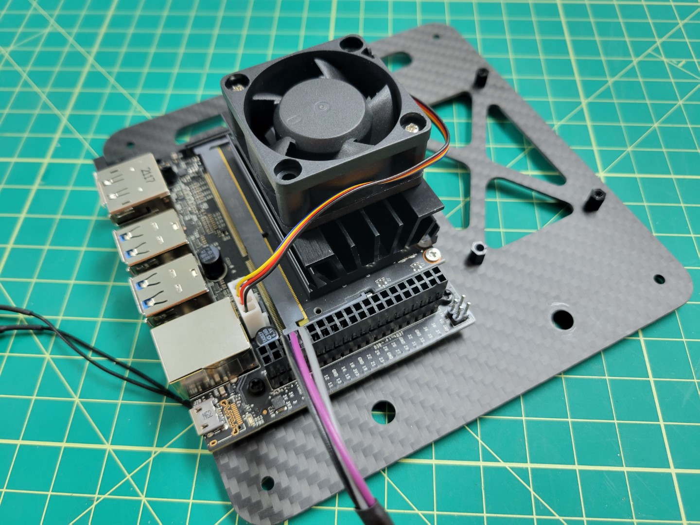
The orientation of your top plate and VMC should look identical to the photo below.
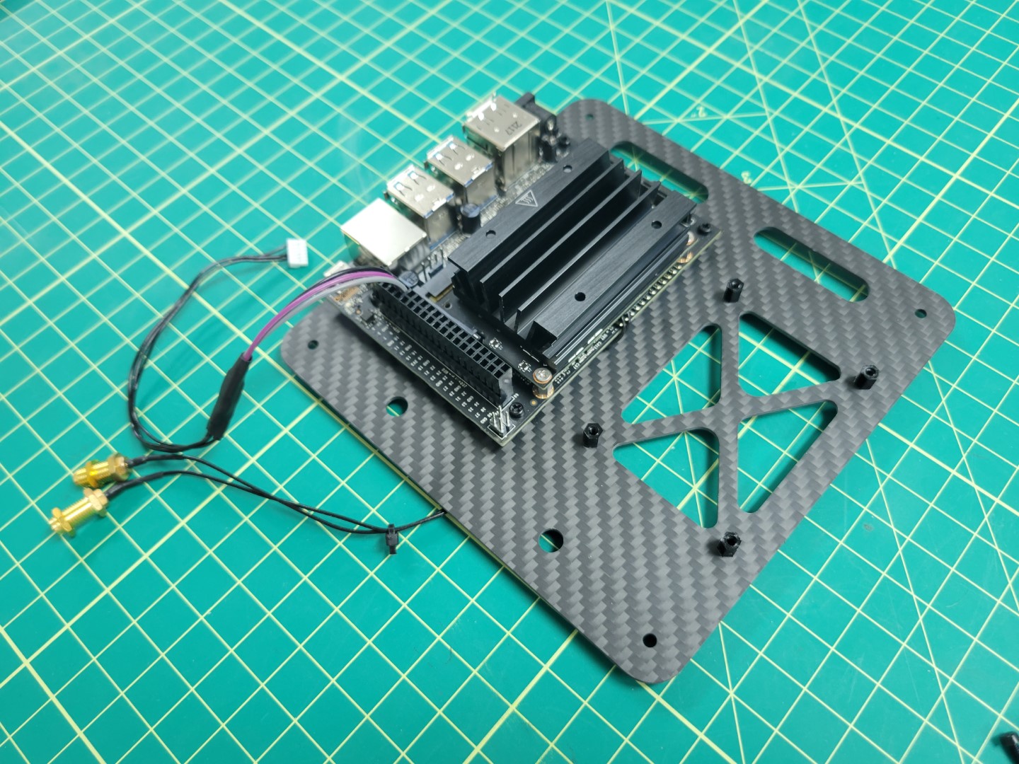
VMC mounted to top accessory plate
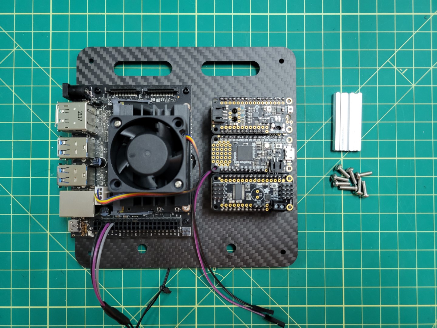
VMC Cooling Fan
During advanced testing you will be running the AVR software stack on your VMC.
Since we make extensive use of the VMC’s CPU and GPU it can heat up significantly.
It’s important to keep your VMC cool and in this section you will install a cooling
fan onto the top of the VMC heat sink.
There are two nuts and bolts included in a small ziploc bag with your cooling fan. Place your cooling fan on top of the heat sink and insert two bolts, on opposite corners, through the fan and the heat sink.
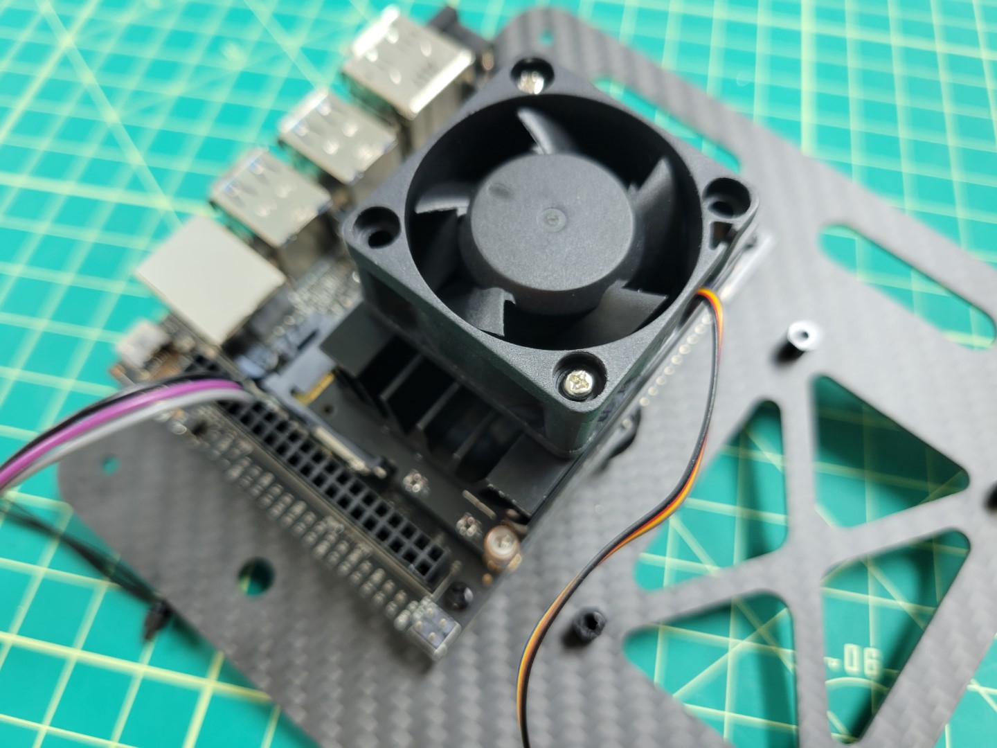
Cooling fan with bolts on opposite corners
Note
The nuts provided with the cooling fan are not self-locking.
It’s a good idea to use a small amount of Loctite to keep them secure.
A small drop of Loctite applied to cooling fan nut
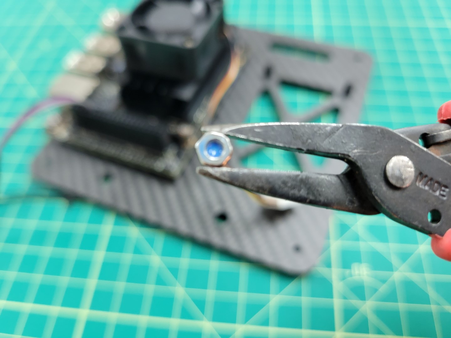
Use needle nose pliers to hold the nut in place and screw the bolt from the top using a Phillips head screwdriver.
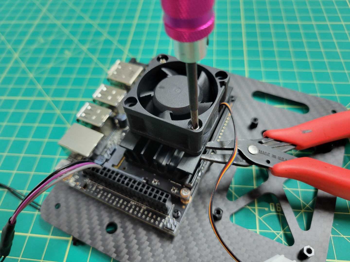
Securing the cooling fan with screwdriver and pliers
Repeat the process for the other nut and bolt. Attach the fan’s power cable to the VMC as shown in the photo below.
Cooling fan connected to power port
Note
The cooling fan automatically turns on to 100% when the VMC is powered on.
This functionality was installed as part of the AVR software, and helps
keep the VMC cool.
PCC Mounting
Let’s proceed with mounting the PCC to the top accessory plate. Make note of the photo below and that the micro USB port is facing outward.
PCC USB port must face outward
We will secure the PCC with four nylon bolts. The easiest way to do this is to remove the top and bottom PCC boards as shown in the photo below.
Securing PCC with four nylon bolts
Replace the boards back into the PCC and mounting is complete!
PCC mounting complete
Top Accessory Plate Mounting
Before we can place the top accessory plate onto the drone we must screw the antenna connectors into place.
Run the VMC and PCC cables through the bottom of the plate as shown in the photo below.
Cable management for top accessory plate
With the VMC and PCC attached to the top accessory plate and wires routed let’s proceed
with mounting the plate over the FC using 40mm standoffs and 10mm M3 screws.
Hardware for accessory plate mounting
Place blue Loctite on one of the 10mm screws.
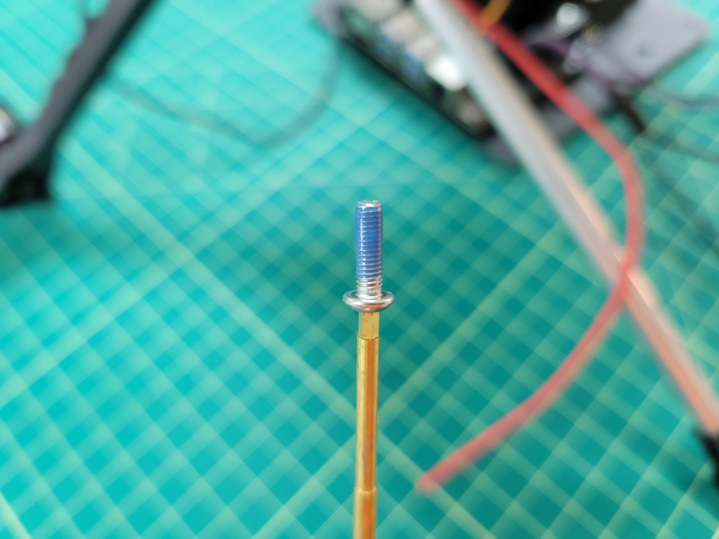
10mm mounting screw with Loctite
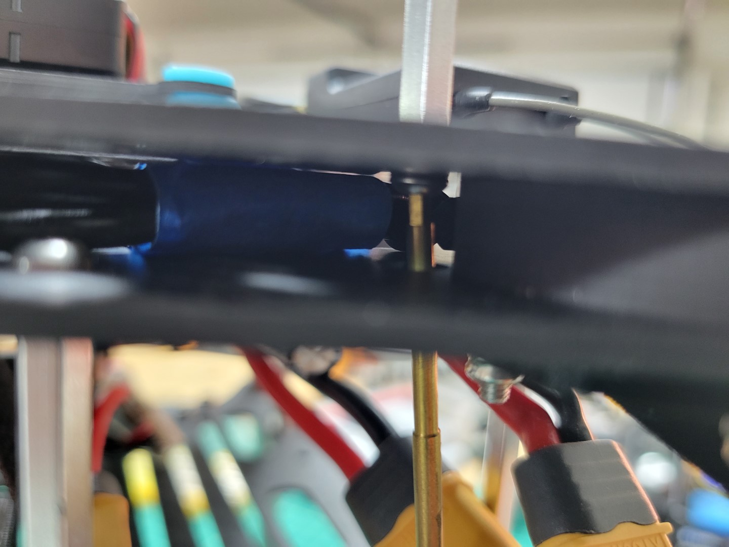
There are four access holes in each corner of the bottom mid-plate, close to where you mounted the 3D printed landing gear.
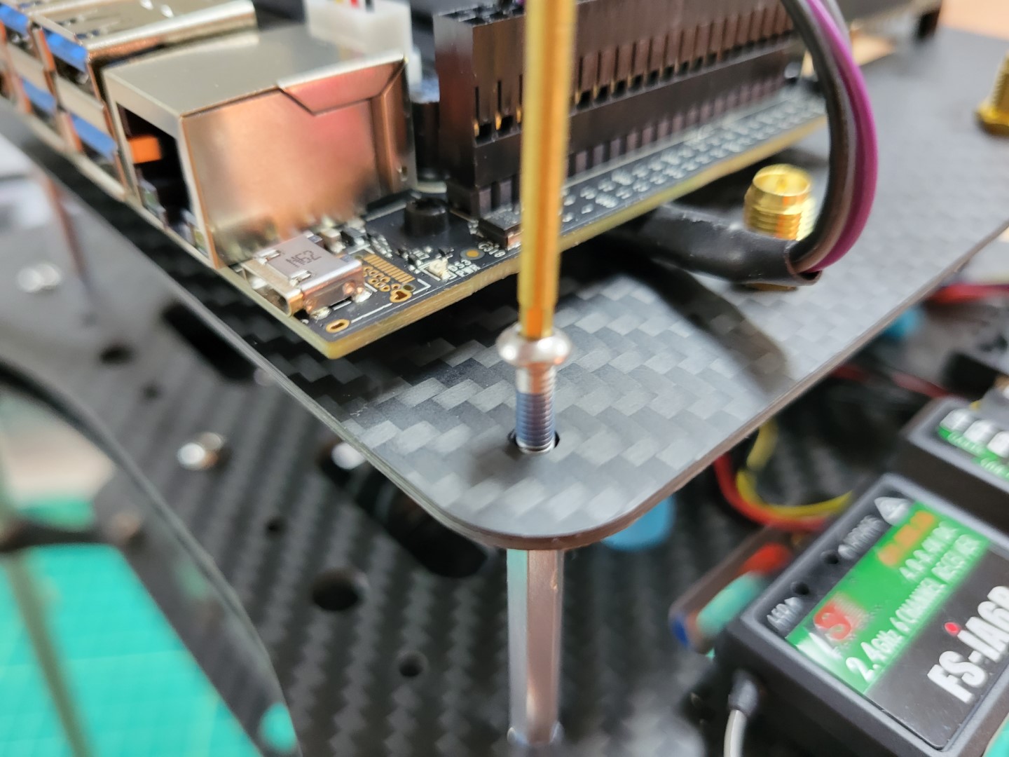
Use a long hex driver to feed the screw up through the bottom accessory plate and through the mid-plate assembly.
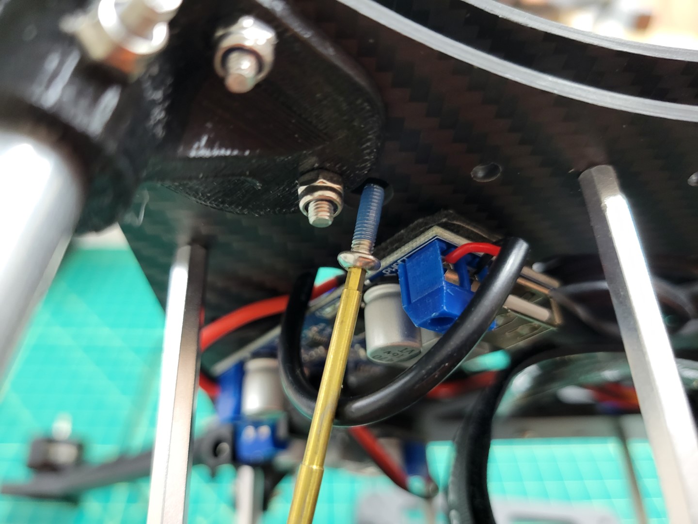
Feeding screw through bottom mid-plate
Another option is to use a short L-shaped hex key to feed the screw into the hole.
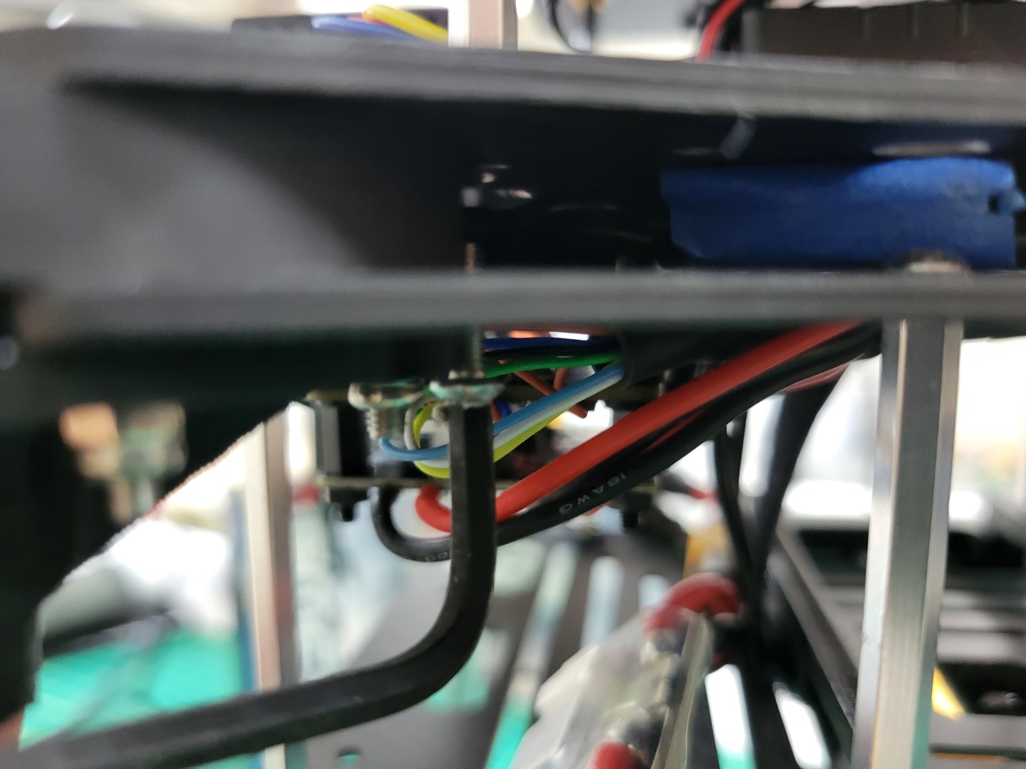
Using hex key to feed screw through bottom mid-plate
Hand tighten the 40mm standoff onto the screw.
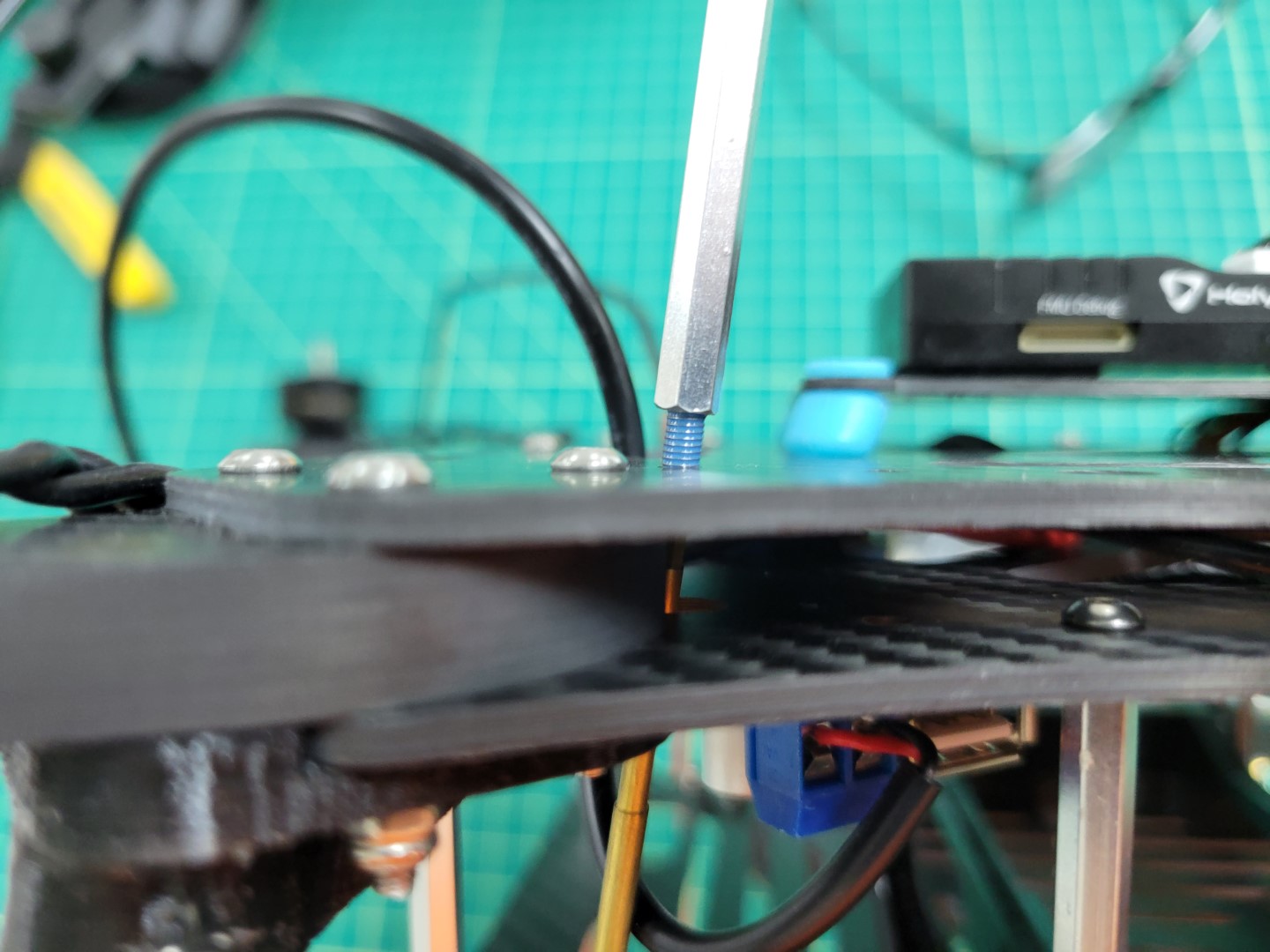
Placing 40mm onto 10mm screw
Securely fasten the standoff and repeat the process for the other three standoffs.
Top accessory plate standoff securely fastened
Connect the telemetry cable from the VMC to the TELEM1 port on the FC.
Telemetry cable connected to TELEM1 on FC
Use four 10mm screws to mount the top accessory plate onto the standoffs. Do not forget to use blue Loctite on each of the screws.
Securing top accessory plate on standoffs
Note
Make sure the top accessory plate is mounted with the VMC on the left and PCC on the right as you’re standing behind the AVR frame.
Top accessory plate secured
Wiring
Connect the barrel plug from the VMC buck converter to the VMC power input.
Note
Make note of the jumper in the photo below.
The jumper must be in place for the VMC to be powered using the barrel jack.
If you need to revert to power over the micro USB port you can move the jumper so that it’s only connected to a single pin.
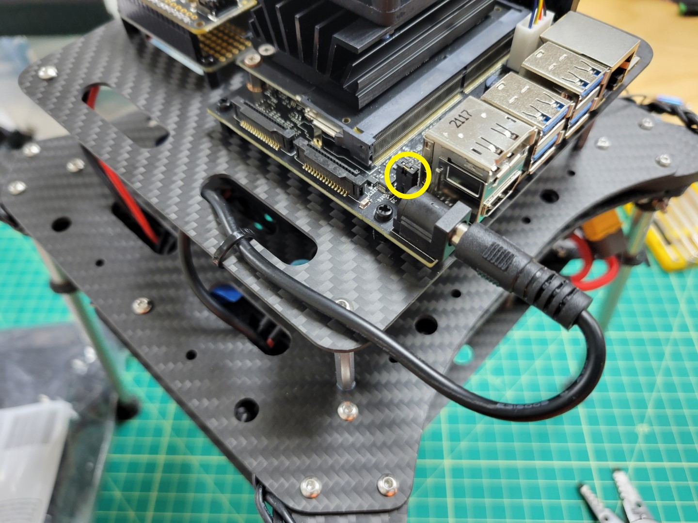
VMC ready to be powered with the barrel plug
Finally, cut the positive and negative wires from the PCC buck converter to length.
Trim 1/8" of shielding from the wires and connect them to the PCC power terminals as shown in the photo below.
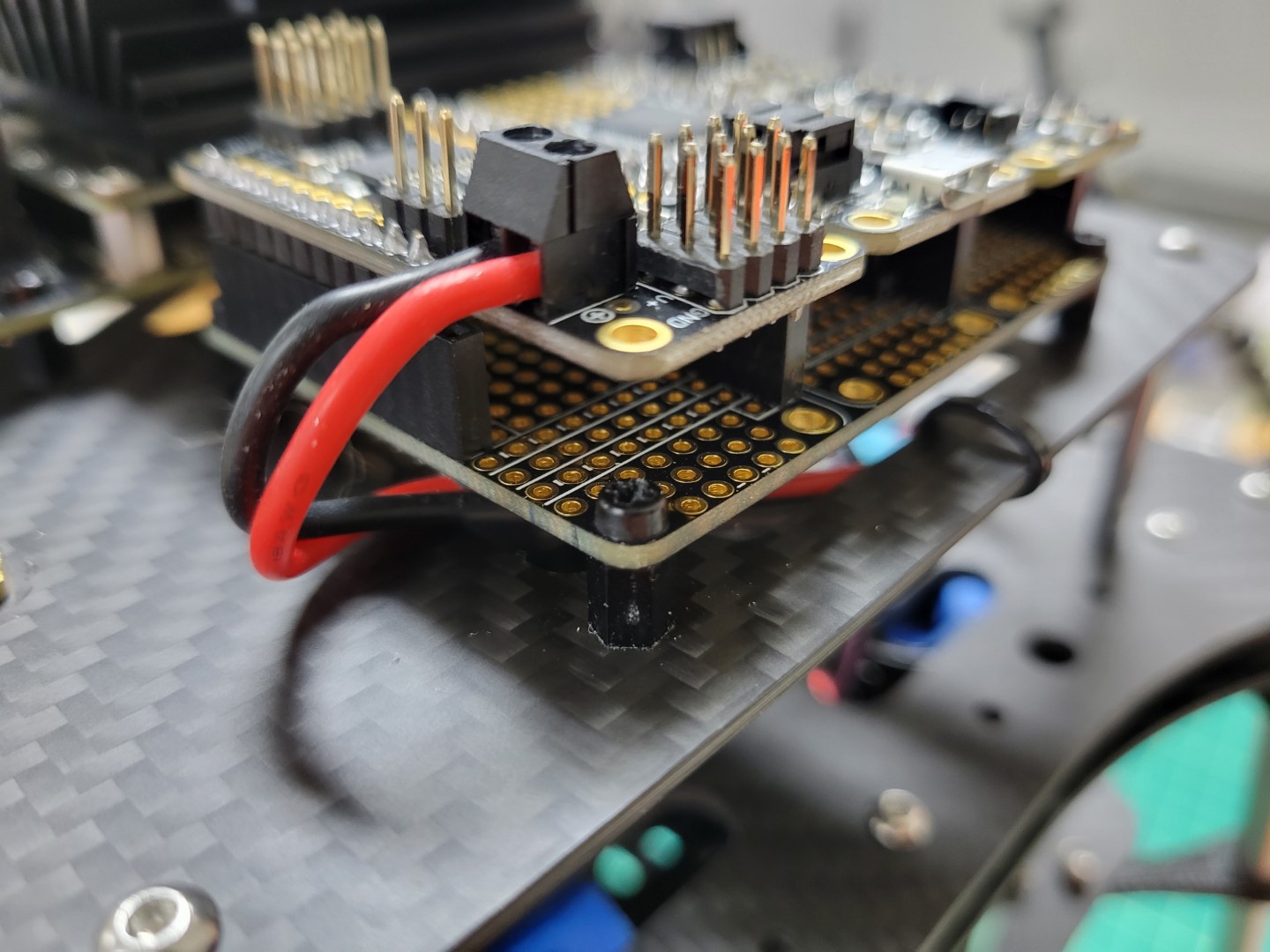
PCC power leads connected
5 - Zed Mini Camera Mounting
The ZED Mini will be mounted to the front of your AVR drone and connected with a USB-C
cable. This camera is instrumental in mapping out
the environment in real-time and providing location updates to the VMC.
This enables your AVR to “see” and maintain it’s current position without GPS!
You should have printed the
Zed Mini mount from the 3D Printing section
of this documentation. The ZED Mini should clip into your 3D printed mount securely.
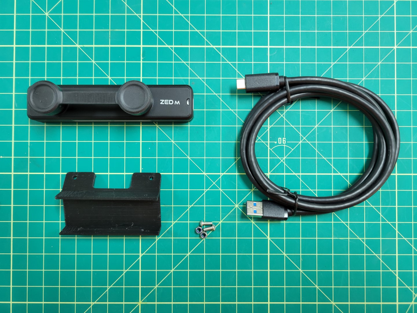
Hardware for mounting ZED Mini
Secure the camera mount to the bottom accessory plate with two M3 8mm screws and lock nuts.
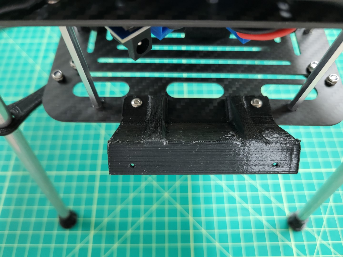
ZED Mini 3D printed camera mount
You will notice that the mount points 45 degrees downward. This aids in tracking both in front and beneath the AVR drone.
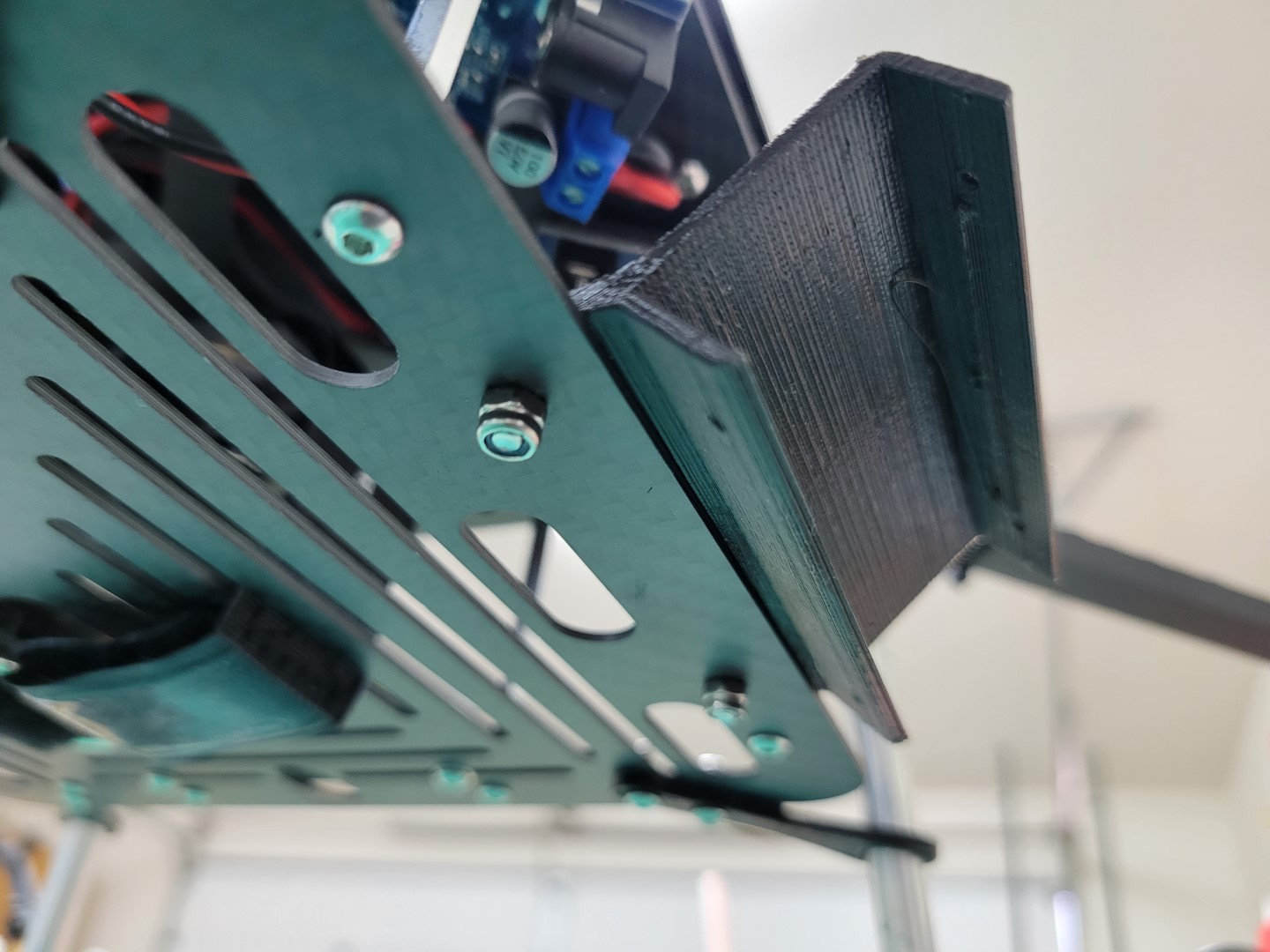
45 degree downward tilt
Snap the ZED Mini into the mount. Make sure that the ridges in the mount snap into the recessed areas on the top and bottom of the camera. You should not be able to slide the camera left and right when properly secured.
Warning
You will notice there is a bit of play when you wiggle the camera back and forth. This can cause problems for ZED Mini’s internal sensors. We will further secure the camera with set screws from the servo hardware.
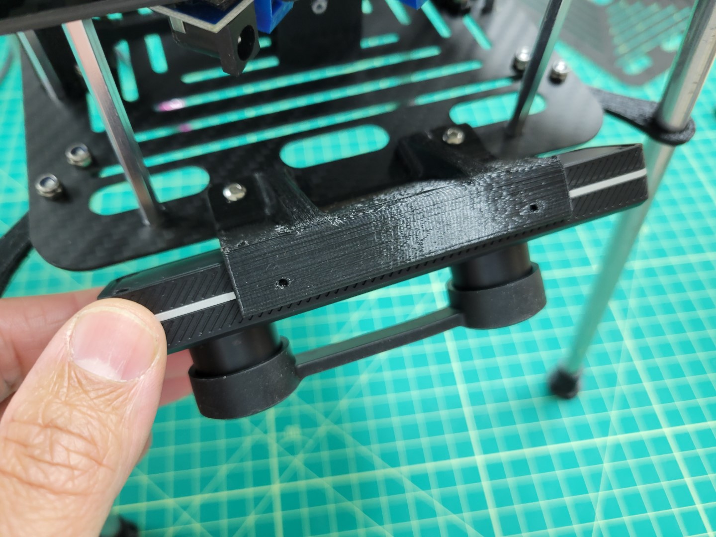
ZED Mini snapped into mount
Locate the large ziploc bag inside the AVR Drone Peripherals box. Inside this bag there are several screws floating around. You will need two of them that look like the ones in the photo below.
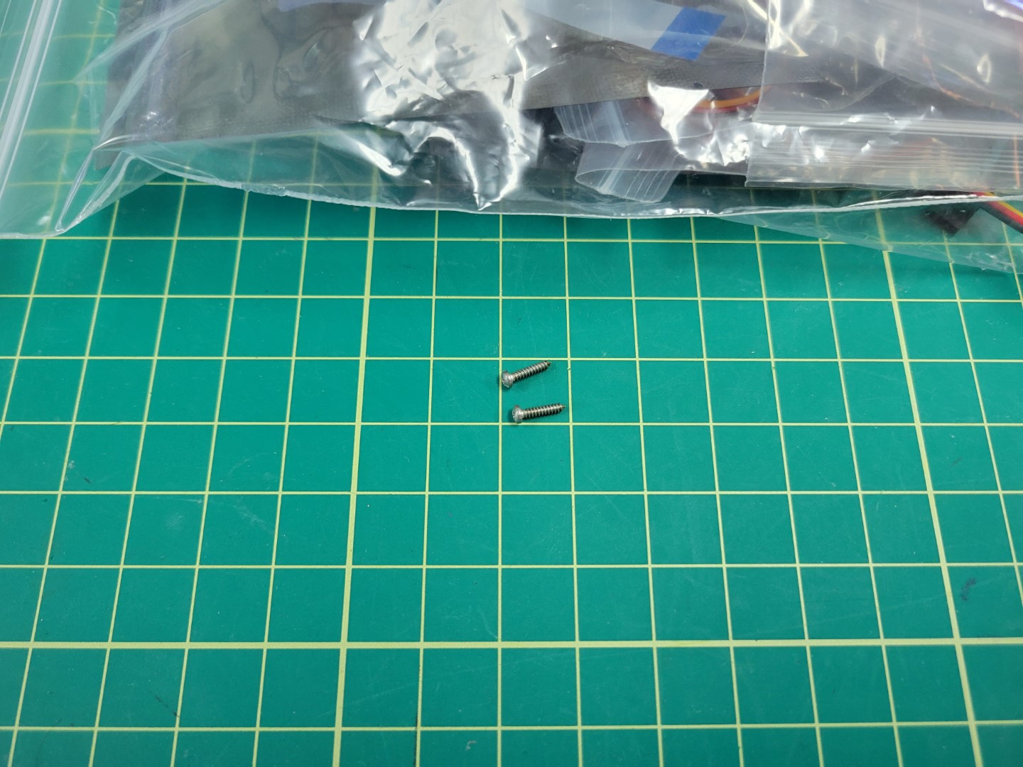
Set screws for securing ZED Mini into the mount
Use a Phillips head screwdriver to thread both screws into the 3D printed mount.
Note
The set screws will not go all the way in. Screw them until you make contact with the threaded hole in the ZED Mini. At this point you will feel a bit of resistance and can stop.
Wiggle the camera left and right to see if there is any play. If so, turn the set screws half a rotation. Repeat the process until the camera is fully secured.
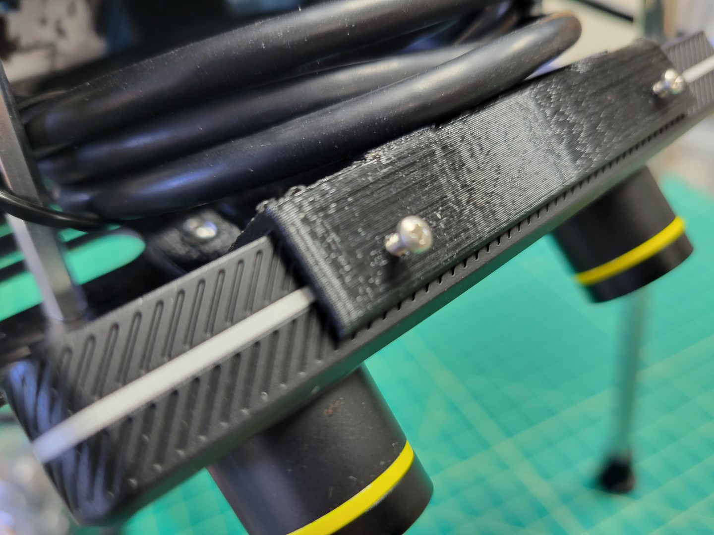
Set screws hold ZED Mini in place
Finally, you can plug the USB cable into the side of the Zed Mini
and into one of the ports on the VMC.
The Zed Mini has a unique USB-C cable so unfortunately it is going to be a little longer
than you need. We suggest rolling the cable up and tucking it between the bottom and
bottom-mid plate for cleanliness.
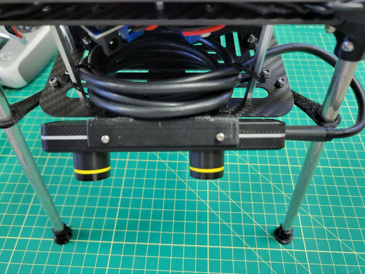
ZED Mini cable rolled out and zip-tied to standoffs
ZED Mini plugged into one of the VMC’s USB ports
Note
As you’re going through the build process make note of any cables that may
obstruct the drone’s propellers. The photos provided throughout this documentation
show how we’ve mounted things and provide a sufficient amount of clearance.
6 - Assembly Review
Great job! Please take a few minutes to watch the video below and
review all that we covered during the advanced hardware modifications.