This is the multi-page printable view of this section.
Click here to print.
Return to the regular view of this page.
Advanced Vertical Robotics Drone Documents

Introduction
Welcome to the documentation for the Bell Advanced Vertical Robotics competition!
Be sure to pay attention to the navigation links on the left and please keep in mind
that this documentation is a living document that will be constantly updated over time.
There will be new sections added, typos fixed, and bugs squashed throughout
this process.
Warning
It is incredibly important to follow the steps outlined in this documentation in
order. The navigation on the left provides a sequential ordering of steps.
Requirements
To be able to successfully compete in AVR, you must have the following
available to you:
- A 3D printer (8.5" cubed) with 1 roll of ABS filament
- A laptop with one of the following:
- Windows 10/11 with admin privileges
- x86 MacOS (M1 chips are not supported yet for AVR)
- Ubuntu 20.04+-based Linux (Pop!_OS, Mint, etc) with
sudo privileges
- Basic shop tools and supplies:
- Zip ties
- Soldering iron
- Screwdrivers
- Basic nut drivers / hex keys (mostly metric M3 / M2.5 sizes)
- Scissors / wire cutters
- Heat shrink
- etc.
A good kit that contains most of the tools that you will need can be found here:
Tool Kit
Useful Links
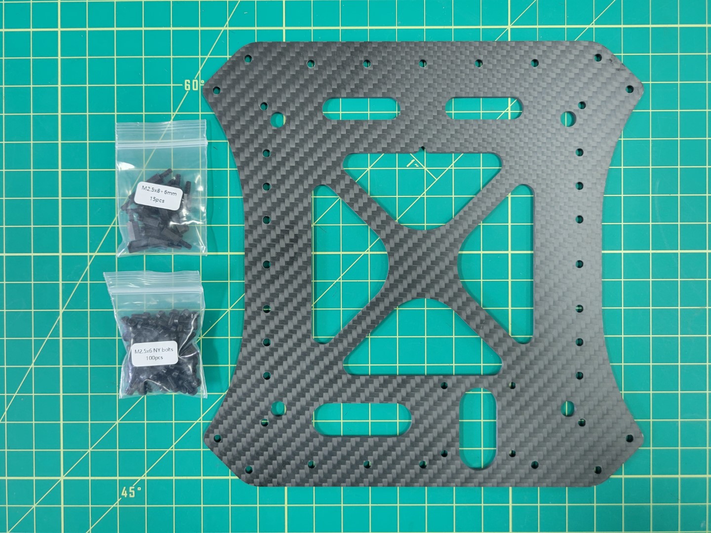
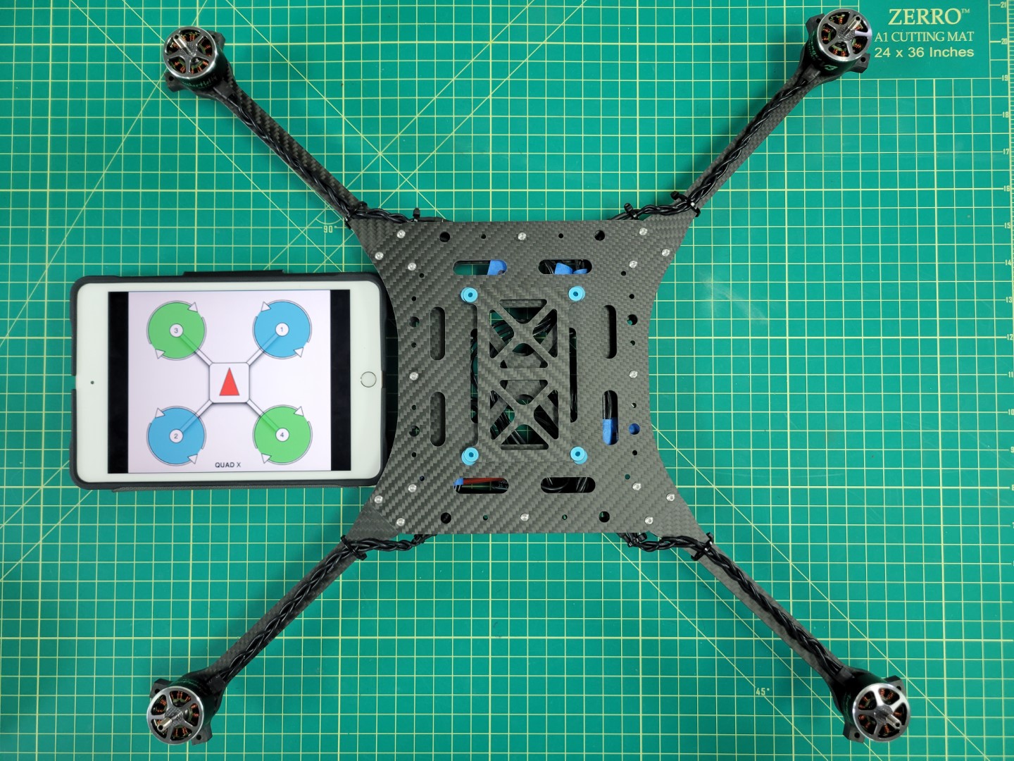
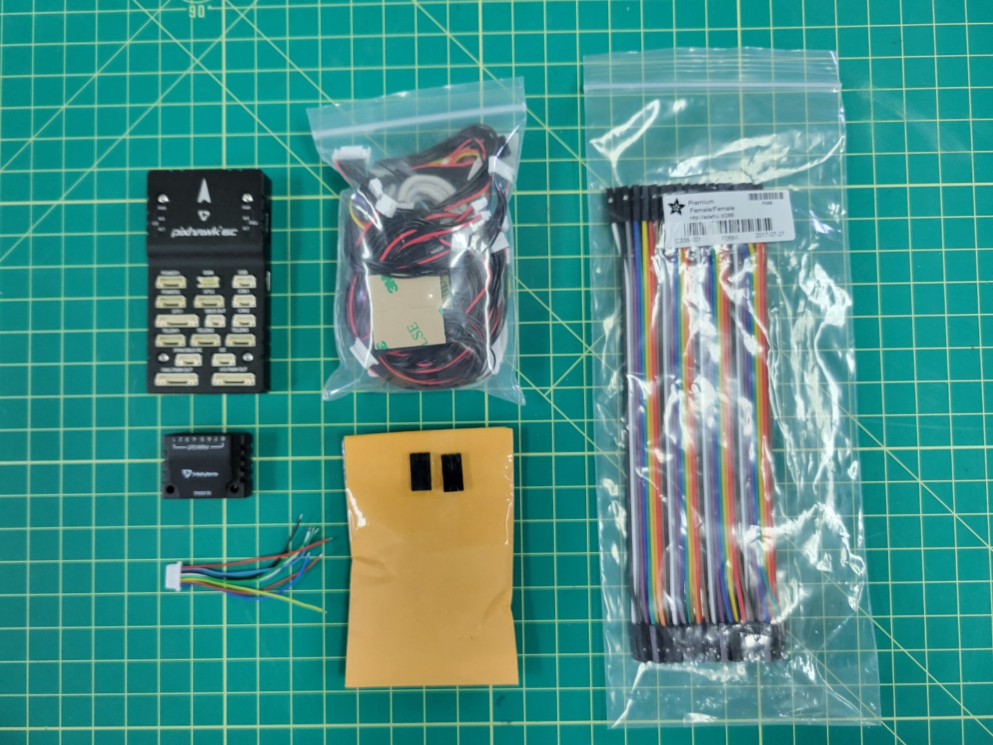
1 - AVR Drone Kit Contents
This page lists the contents of the Bell AVR drone kit necessary for the basic stabilized flight goal
As you read through this page please be sure to refer to the
glossary,
which contains definitions of many of the components on this page.
The Bell AVR drone kit includes all of the components required to build your
own autonomous quadcopter. The kit provides a frame, motors, electronic speed
controllers, flight controller, and several additional peripherals.
This section will cover a majority of the components included for basic
assembly of the drone.
Boxes in AVR Kit
The AVR kit will contain the following boxes. Be sure to read the label on each box to gain a high level understanding of the components inside.
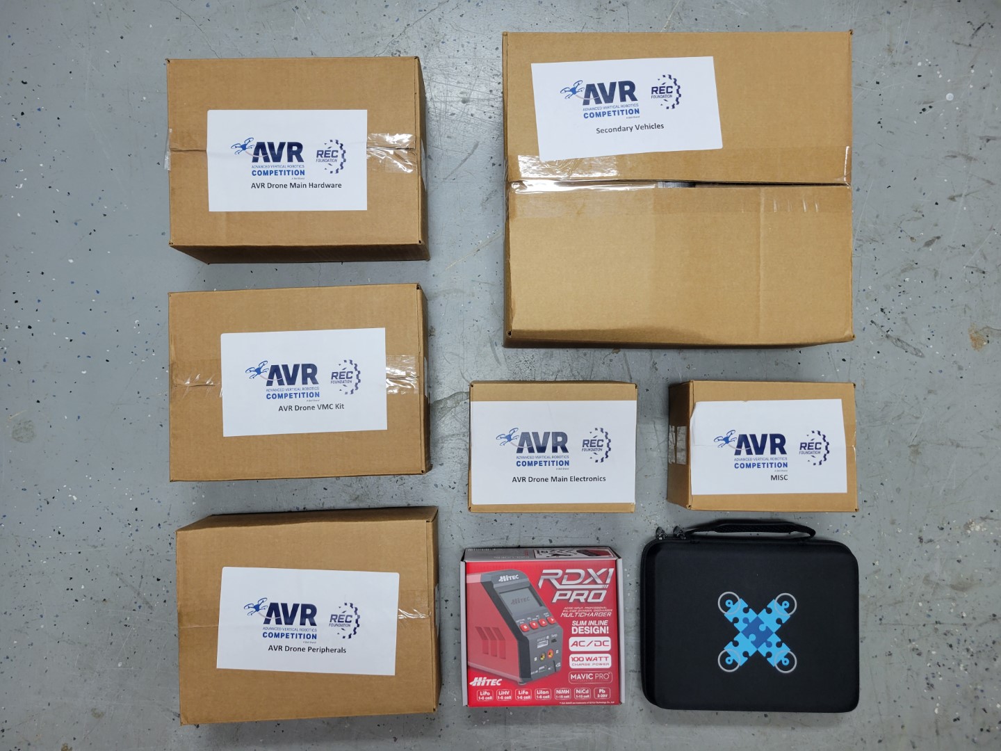
AVR kit boxes from first shipment
Components for Basic Drone Assembly
The photo below shows the main components necessary for the first phase of the build, which consists of assembling the drone hardware, configuring the flight controller, and becoming familiar with manual, stabilized flight.
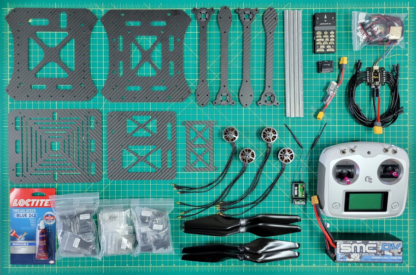
AVR kit components for manual flight
Components for Advanced Drone Assembly
In the second phase of the build you will be adding several peripherals to your AVR drone, installing software, and configuring parameters for better performance. These modifications will allow you to fly in a mode known as “Position Hold” where the drone will maintain position and altitude. This will lead to a much better experience when it comes to competition day.
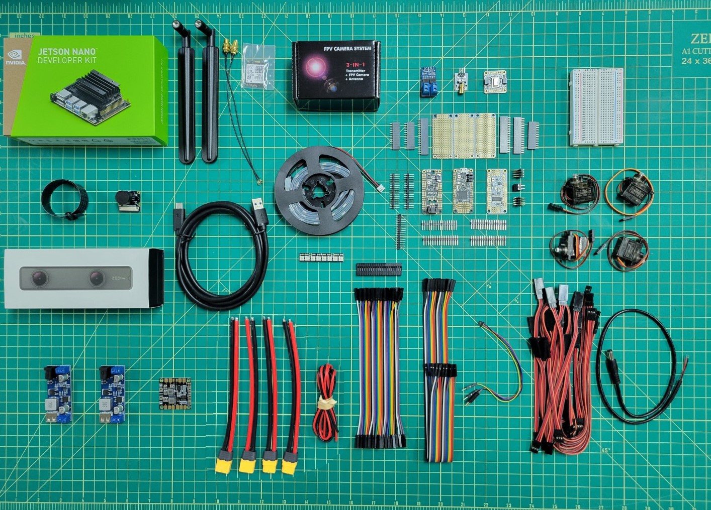
AVR kit components for position hold flight
2 - 3D Printing
This section shows the the required 3D prints for this year’s drone
For AVR, you’ll need to 3D print some parts for your drone.
While not needed immediately, these are good to get started with:
Explore each of the subsections to see what you’ll need to print.
Downloading
To download parts select the download button.
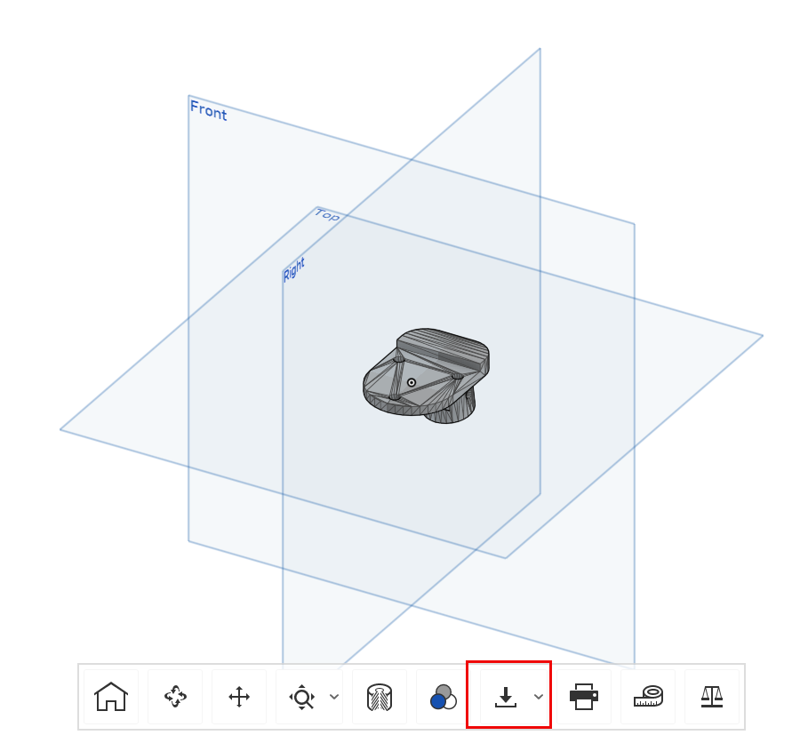
Onshape Download Button
Change the units from Meters to Millimeters.
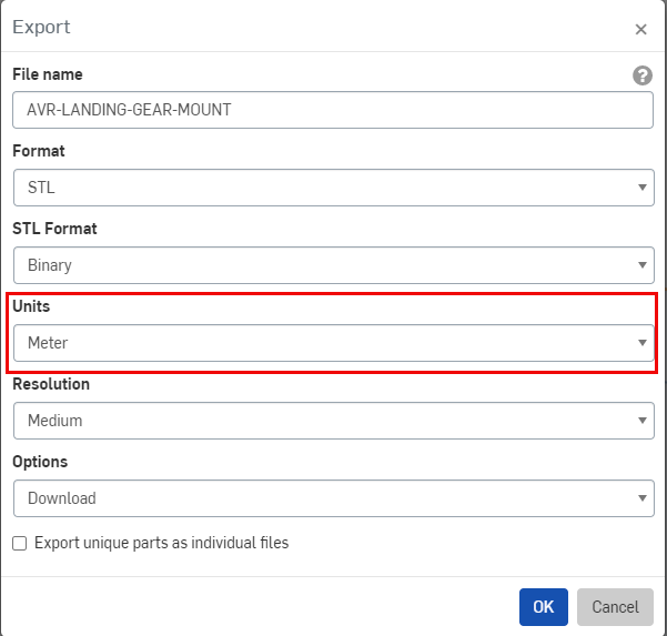
Onshape Units Selection
The export page should resemble the following.
Press OK.
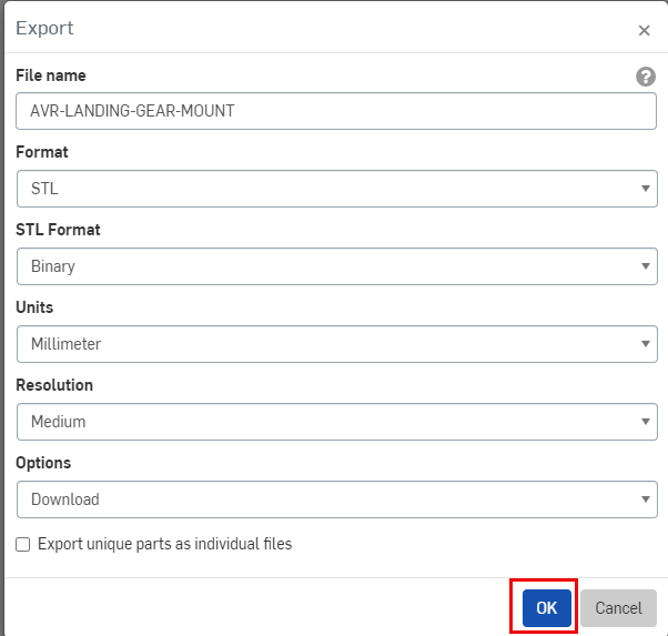
Onshape Export Page
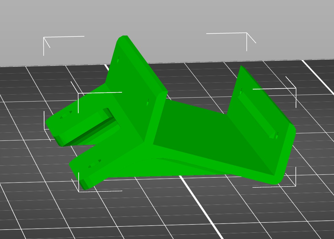
2.1 - Landing Gear
3D prints for the landing gear
- AVR-LANDING-GEAR-MOUNT (x4)
- AVR-LANDING-GEAR-BRACE (x4)
- AVR-LANDING-GEAR-FOOT (x4)
Note
For the landing gear it is highly advised that you print with 100% infill as these are
going to be parts that will need to with stand the impact of landing.
2.2 - Mounts
3D prints for mounting the ZED Mini camera
- AVR-CAM-ZED-MINI-MOUNT (x1)
- AVR-BATTERY-STANDOFF-SMC (X1)
An infill of 15% should be sufficient for these parts.
For best prints, it is advised that you rotate the part onto its back for printing.

Zed Mini Standard Orientation
Zed Mini Print Orientation
2.3 - Gimbal
3D prints for the thermal camera gimbal
- AVR-GIMBAL-BASE (x1)
- AVR-GIMBAL-PAN (x1)
- AVR-GIMBAL-TILT (x1)
An infill of 15% should be sufficient for these parts.
3 - AVR Drone CAD Model
Teams can find a representative model of the drone by following this
link to Onshape
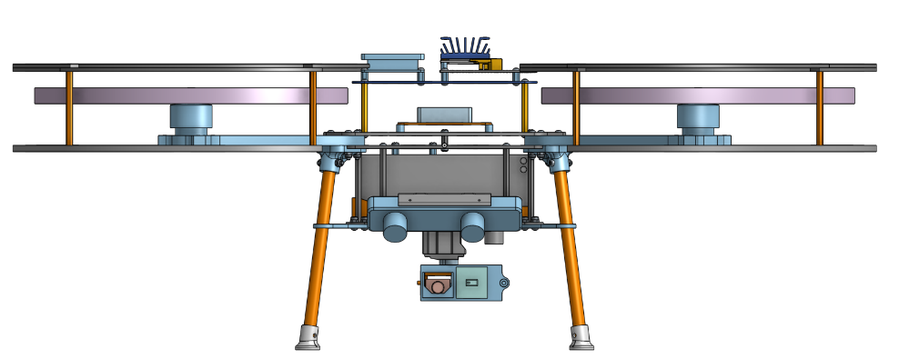
Front View
Isometric View
Side View
4 - Basic Drone Assembly
This section guides you through the assembly of the drone kit
This section is a complete guide on how to build the Bell AVR drone.
It is recommended to read this guide thoroughly and in order.
At the bottom of each page, there are navigation buttons that will allow you to
proceed to the next section or visit the previous one.
Our goal in this section is to get you to Checkpoint #1: Flight Test,
which consists of the ability to manually pilot the drone indoors in a
stabilized flight mode.
Below are photos of what your assembled kit will look like before your
first flight test.
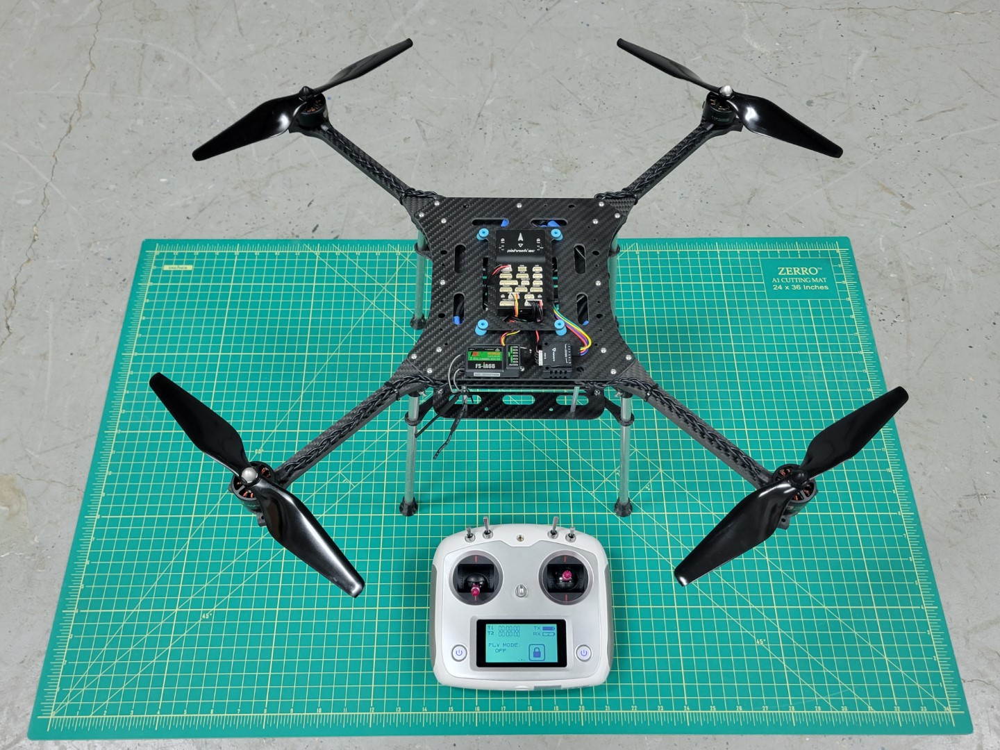
AVR drone ready for first flight
AVR drone right side view
A simple block diagram can be used to represent the components of the basic drone.
As you move throughout this documentation keep these details in mind.
It will help you gain a high-level understanding of what we’re trying to accomplish.

Block diagram of basic drone components
Let’s get started with assembly!
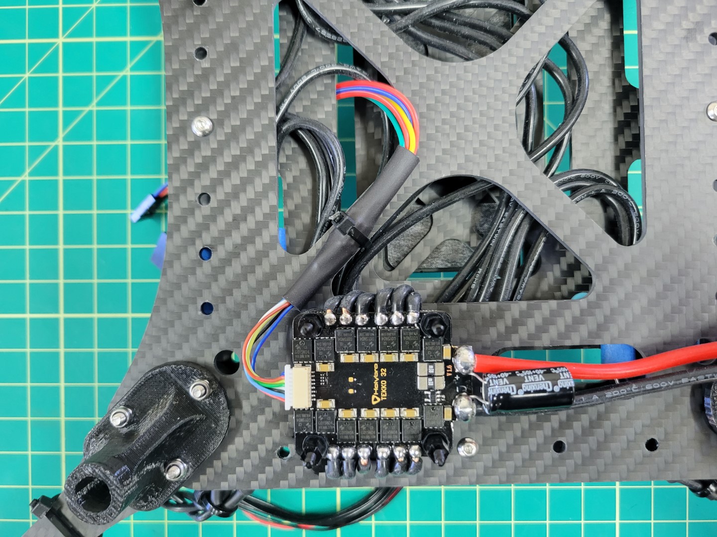
4.1 - ESC Mounting
This page will explain how to mount the 4-in-1 ESC to the midplate
Mounting
Note
As you work through each section of the AVR build process we highly encourage you to read to the bottom. Then come back to the top and begin building!
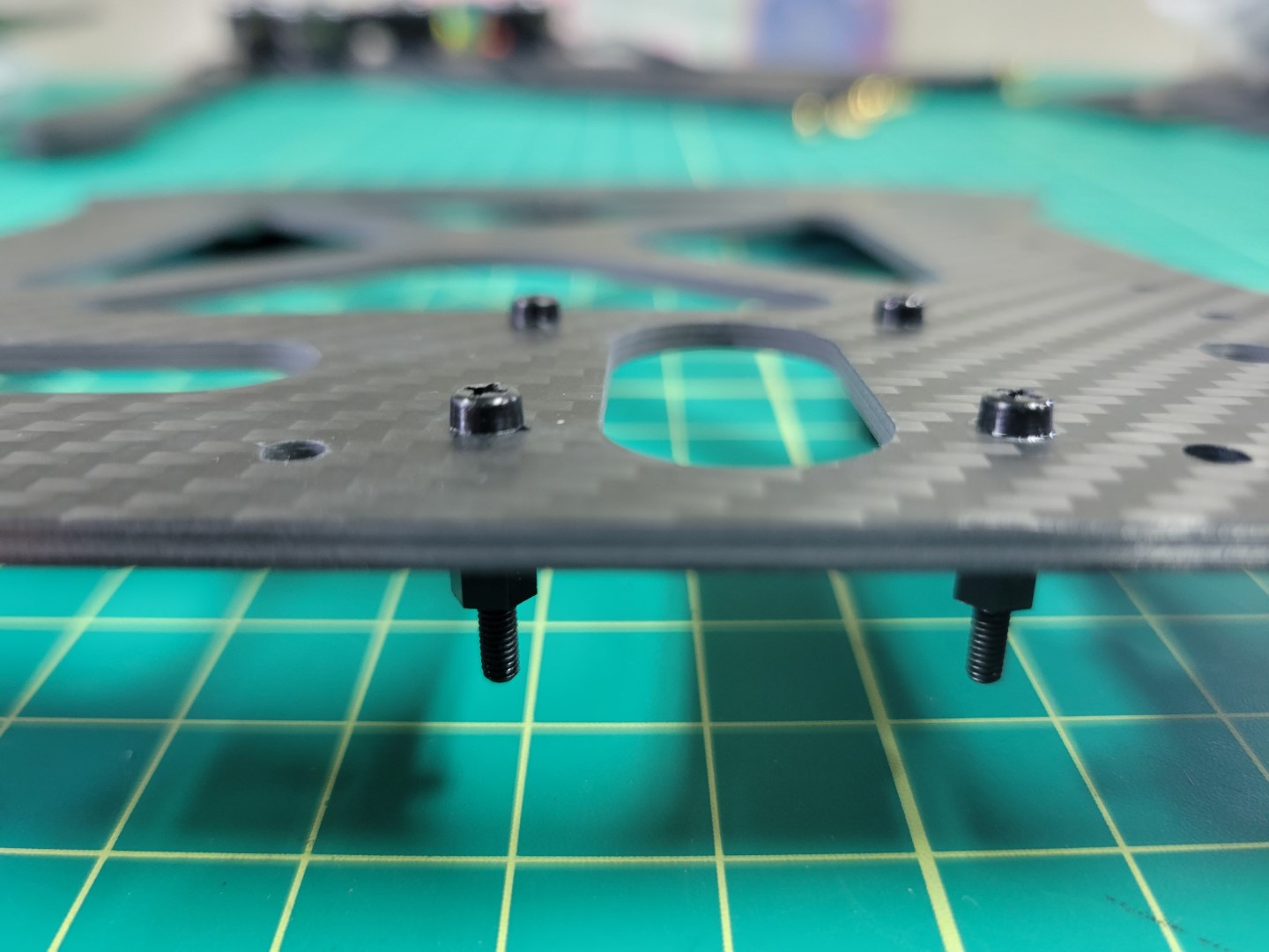
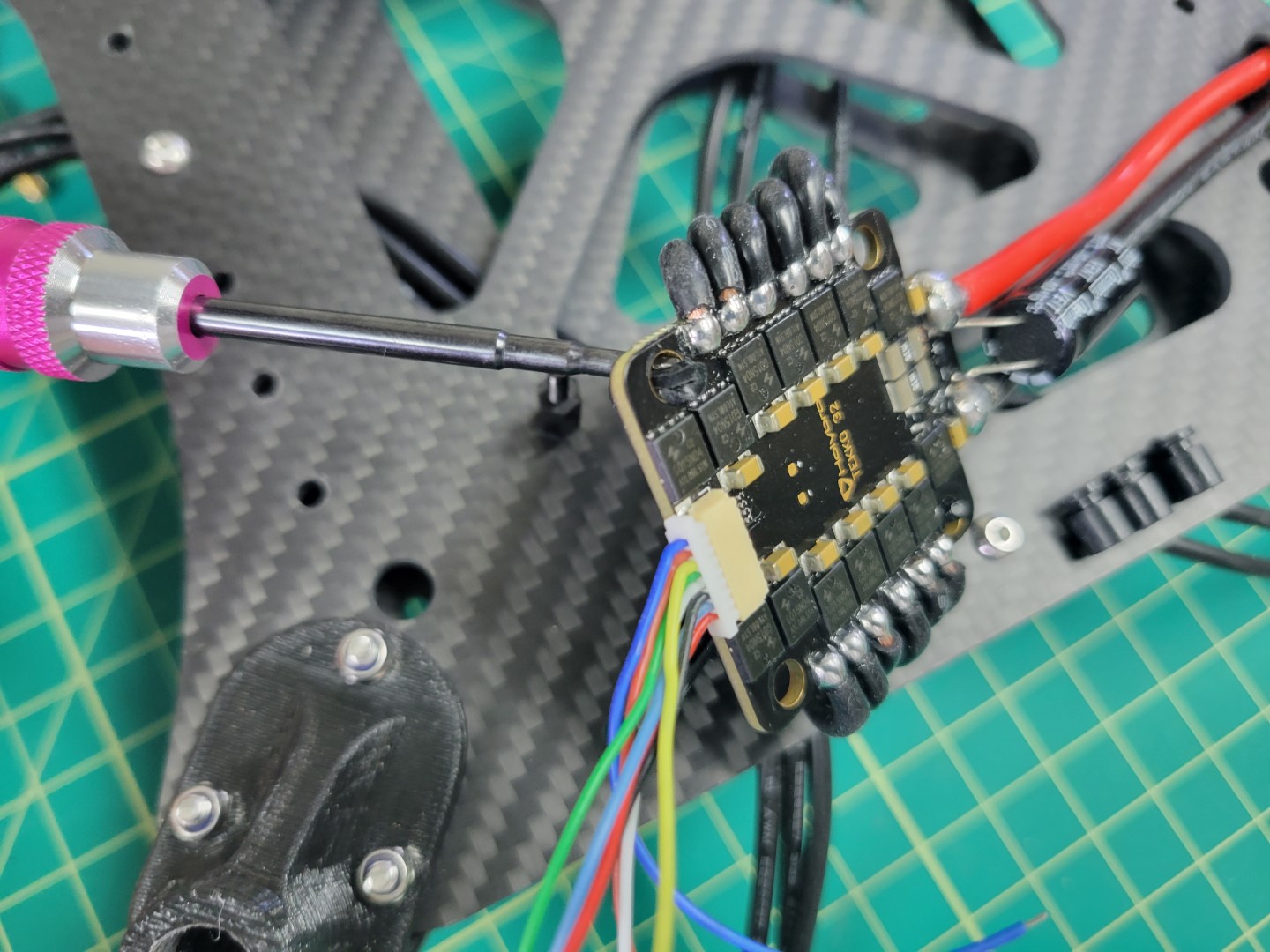
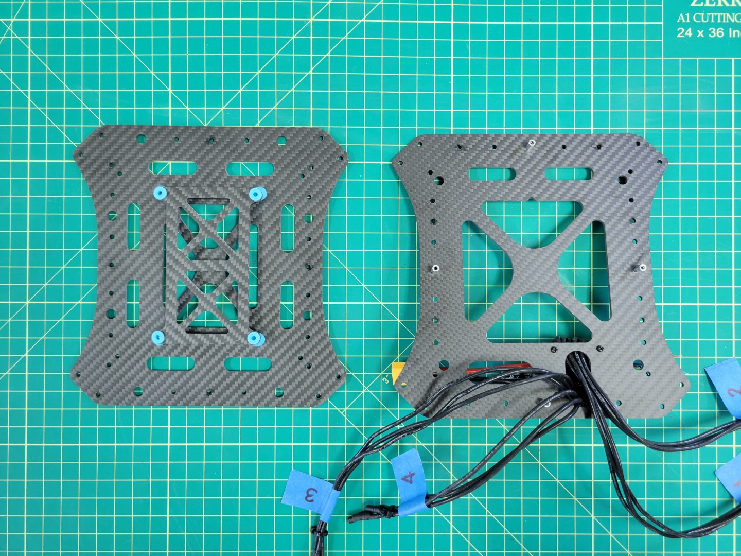
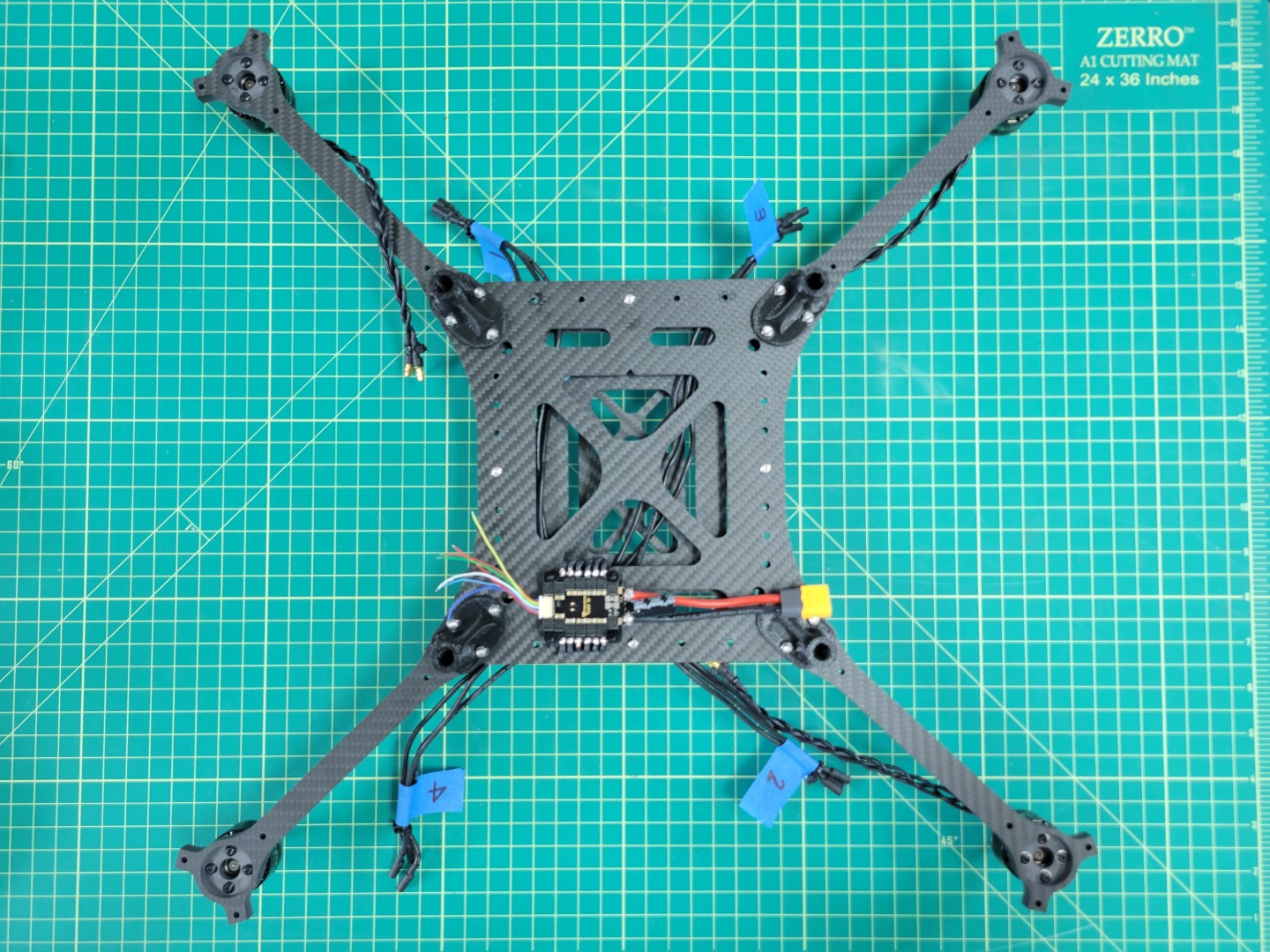
The Tekko32 4-in-1 ESC will be mounted underneath the bottom plate of the middle section. Locate the bottom plate as shown in the photo below. You will notice a small notch that indicates the front of the plate.
Look for the 6mm threaded nylon standoffs and bolts that will be used to mount the ESC. It’s important that the electronics from the ESC do not make contact with the carbon fiber plate. This could lead to a potential electrical short.
Mid bottom plate with nylon hardware
Your AVR kit comes with a small tube of blue Loctite. You’ll want to place a small drop of this inside each of the threaded standoffs. Don’t overdo it. Loctite can get messy and a little will go a long way.
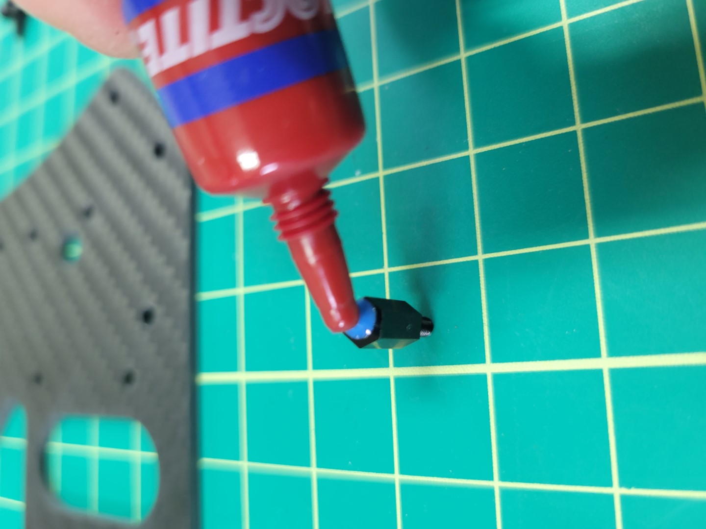
Applying blue Loctite to 6mm nylon standoff
Mount the standoffs in the right rear corner of the plate facing downward as shown in the photo below.
Warning
Be careful not to overtighten. Nylon hardware is easy to strip. Gently tighten and let Loctite do its job. Loctite will set in about 10 minutes and fully cure after 24 hours.
Nylon bolts and standoffs in place
Flip the plate over so that the threaded standoffs are facing up. Run all of the ESC leads through the provided cutout.
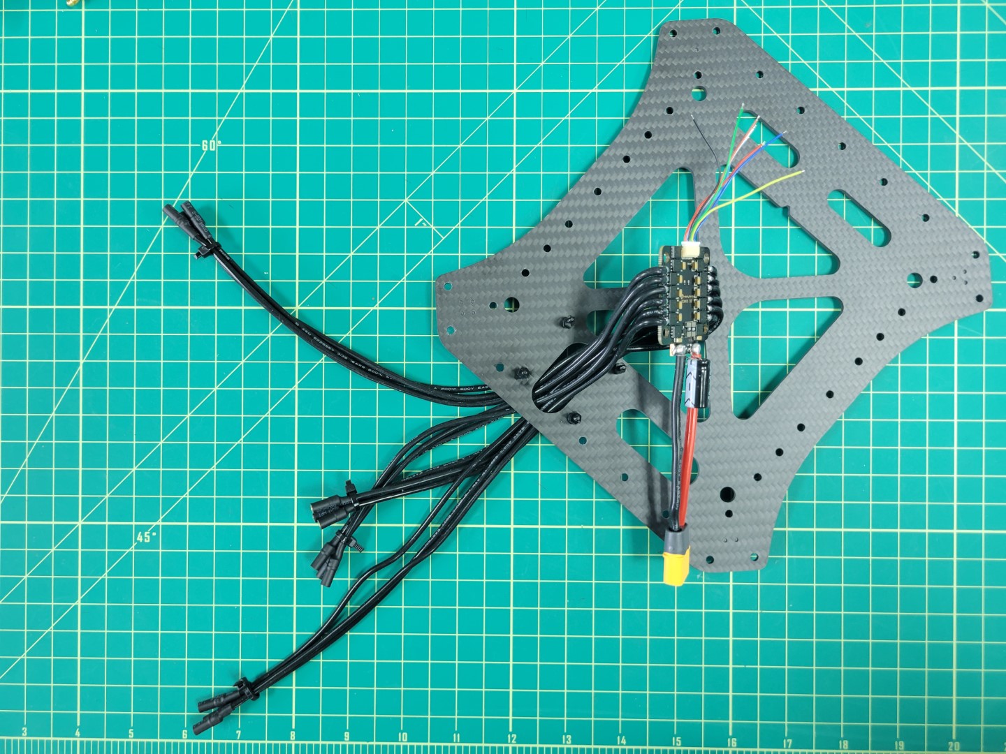
Feeding ESC leads through the plate
Warning
Use care when feeding the ESC leads through the cutout. Edges of carbon fiber can be sharp and you do not want to accidentally strip any of the shielded cables.
Before placing the ESC on the standoffs you will need to install the rubber dampeners. You can find these inside a small ziploc bag in the ESC packaging.
The purpose of these rubber dampeners is to keep the ESC secure when placed onto the nylon standoffs.
ESC dampeners prior to installation
Working with rubber dampeners can sometimes be a bit challenging. We recommend using a tool with a flat tip such as a 2.0mm hex driver that you will be using throughout the AVR build process. Do not use a sharp or pointy tool such as a Phillips head screwdriver. You do not want to accidentally pierce the rubber dampeners.
Pinch the dampener and feed it into the hole with your fingers. Use the hex driver to push the rim of the dampener into place as shown in the photo below. Repeat the process for all four corners of the ESC.
Using a 2.0mm hex driver to install rubber dampener
Once all the dampeners have been installed proceed to place the ESC on the standoffs. You will need to use a bit of force to push the ESC into place.
Make sure the yellow XT60 connector is facing the towards the inside of the plate and not hanging off the edge.
ESC placed onto 6mm standoffs
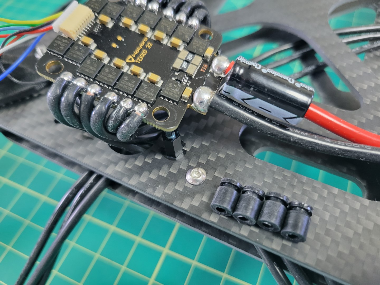
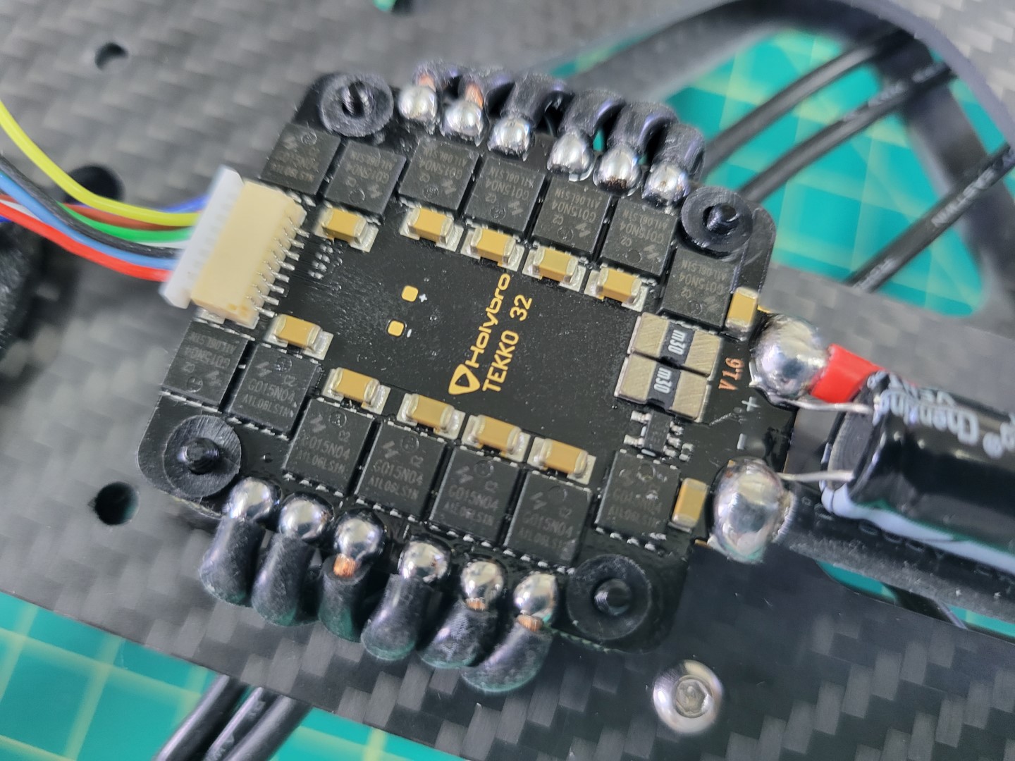
Now that the ESC is in place use four more 6mm threaded standoffs to secure it. In the next phase of the build process you will “stack” a Power Distribution Unit (PDU) on top of the 4-in-1 ESC. Don’t forget to use a dab of Loctite on the standoffs.
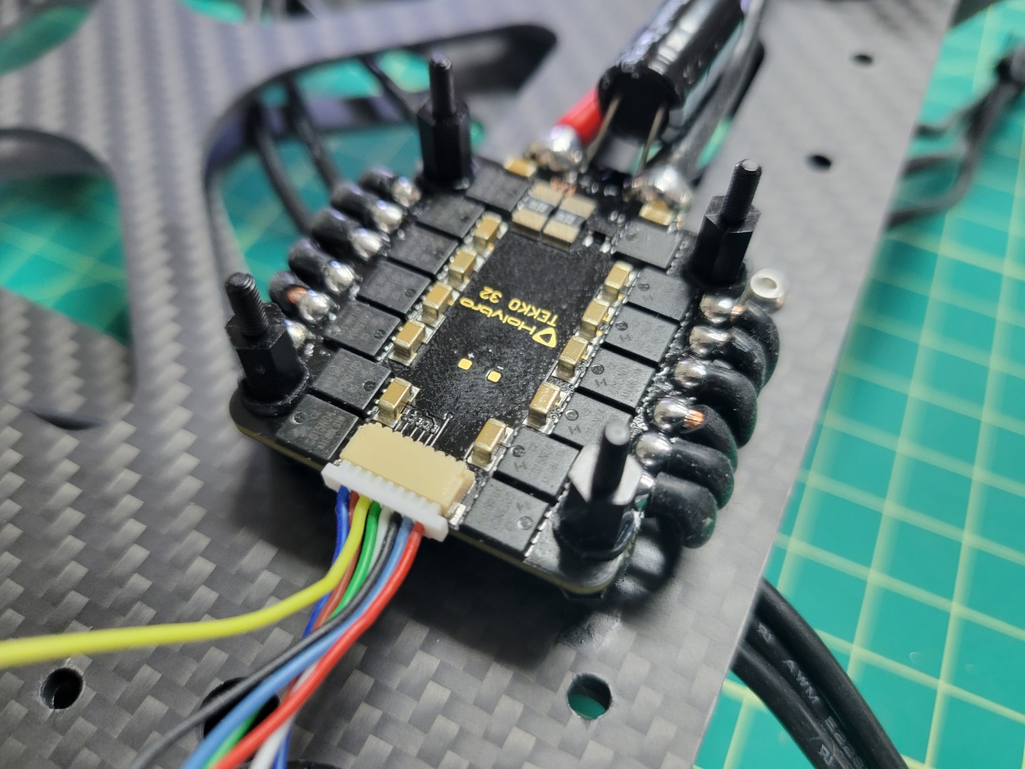
ESC secured with standoffs ready for PDU
ESC mounting is complete! Before proceeding we recommend following the tip below.
Tip
Labeling your ESC leads will save you time and frustration throughout the build! The diagram below shows how each group of three ESC leads match up with motors M1-M4. In the next section we will install the middle top plate, which will make it challenging to see which lead goes to a given motor. Do this step now and you will be glad you did!
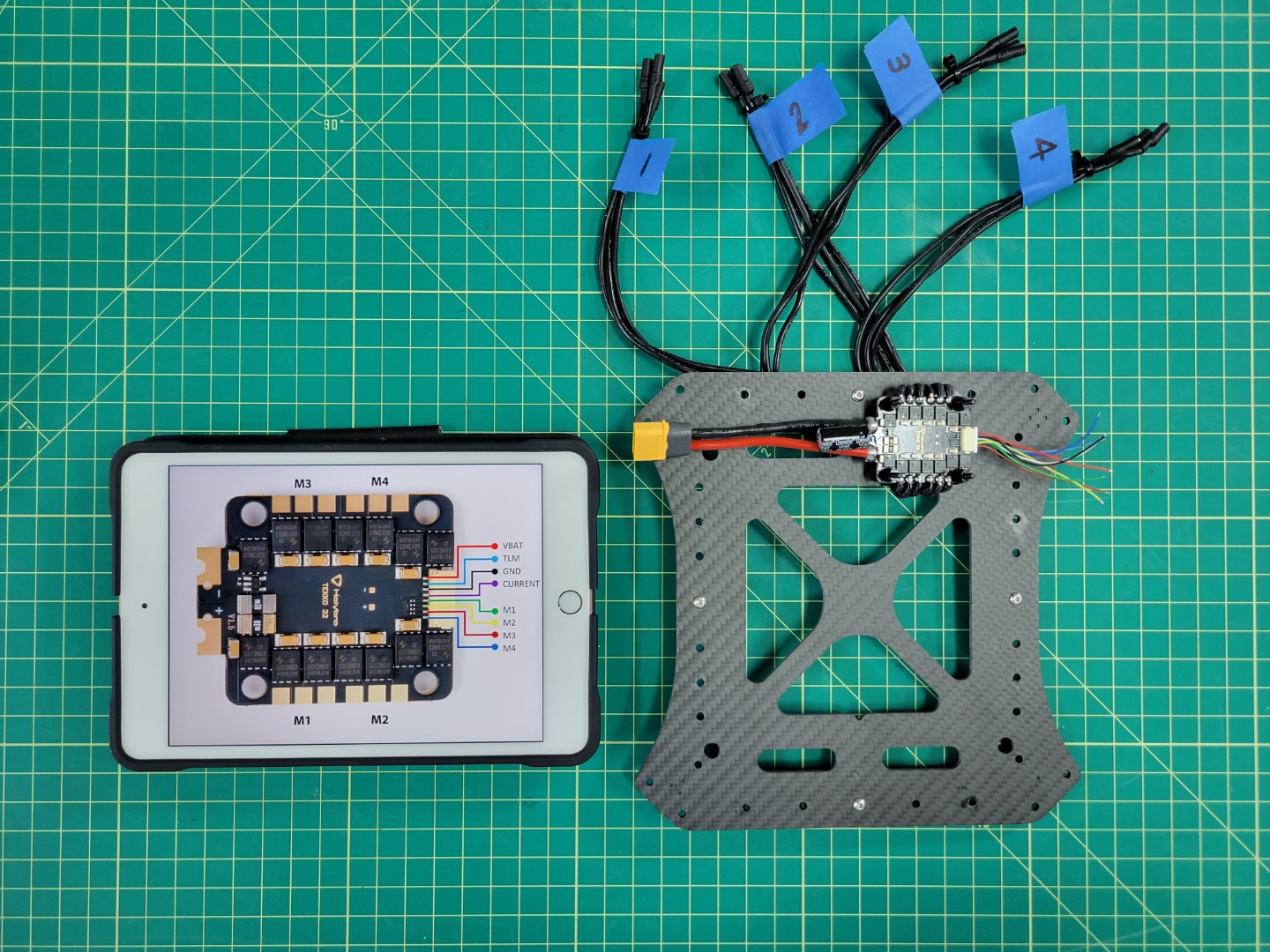
Labeling ESC leads saves time and frustration
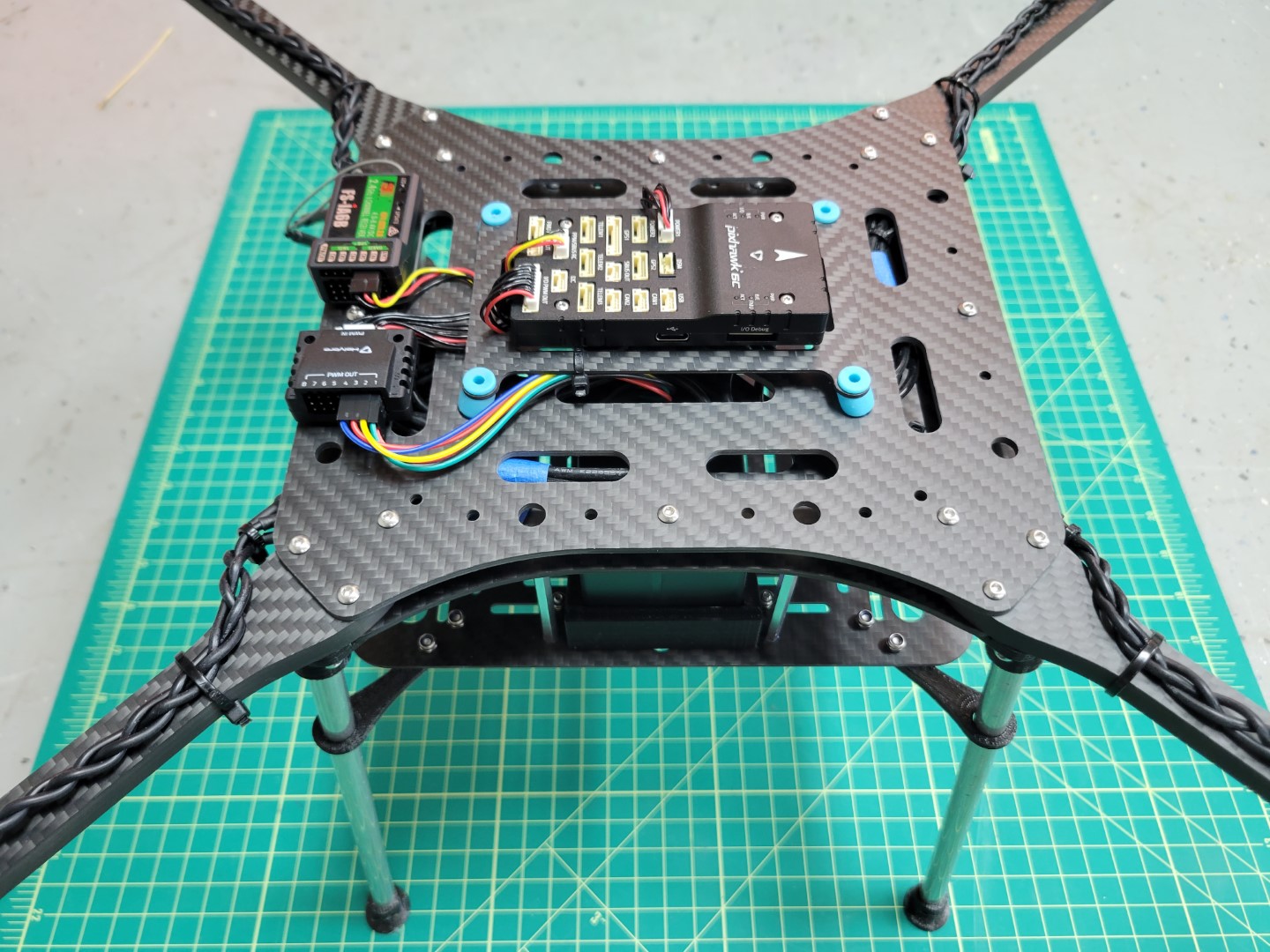
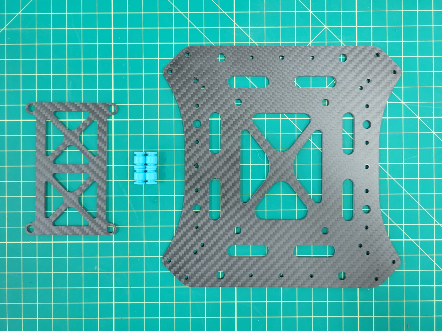
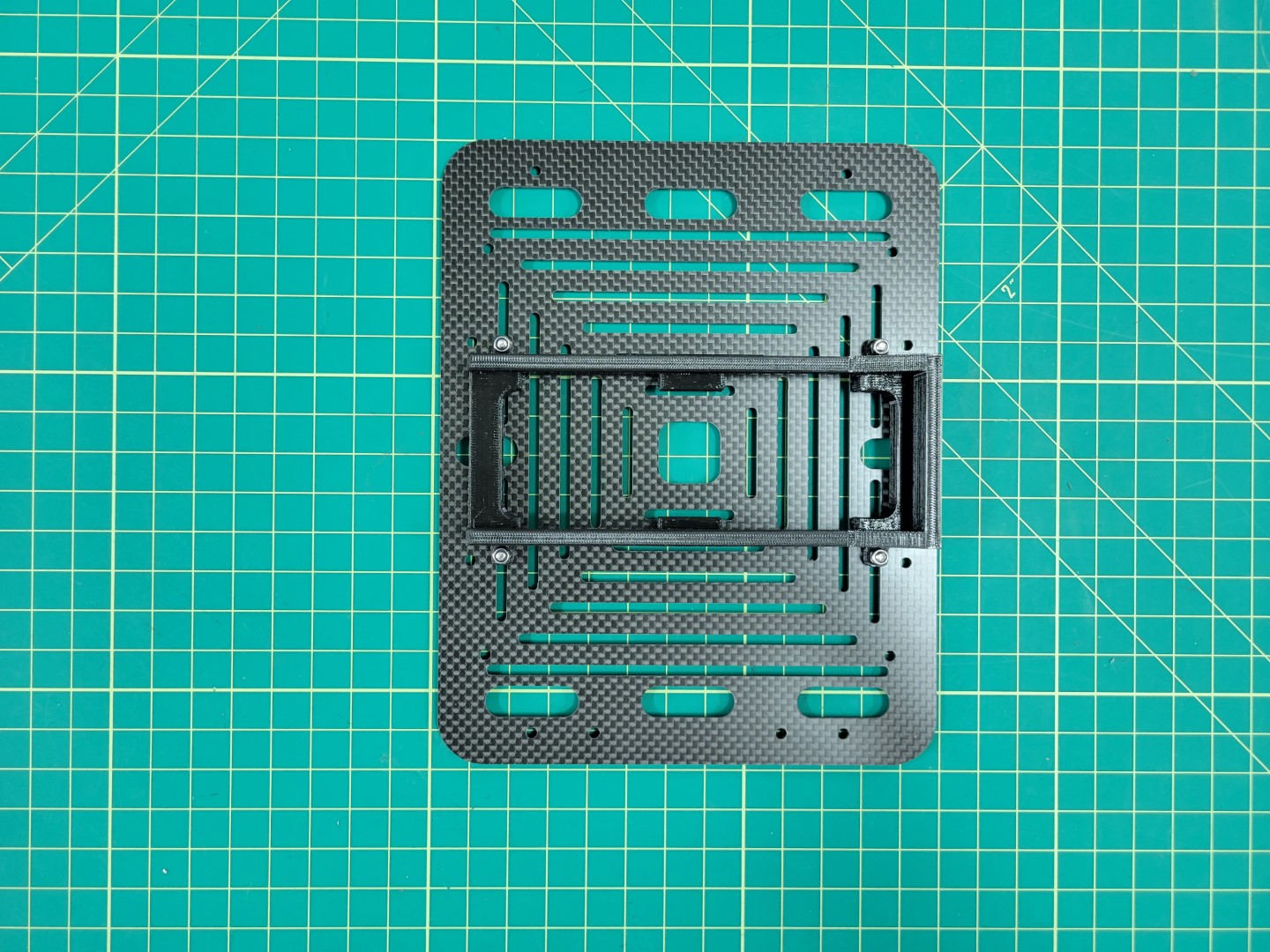
4.2 - Mid Plate Assembly
The mid plate assembly is an essential part of the AVR frame. It holds the motor arms, ESC leads, and Pixhawk FC.
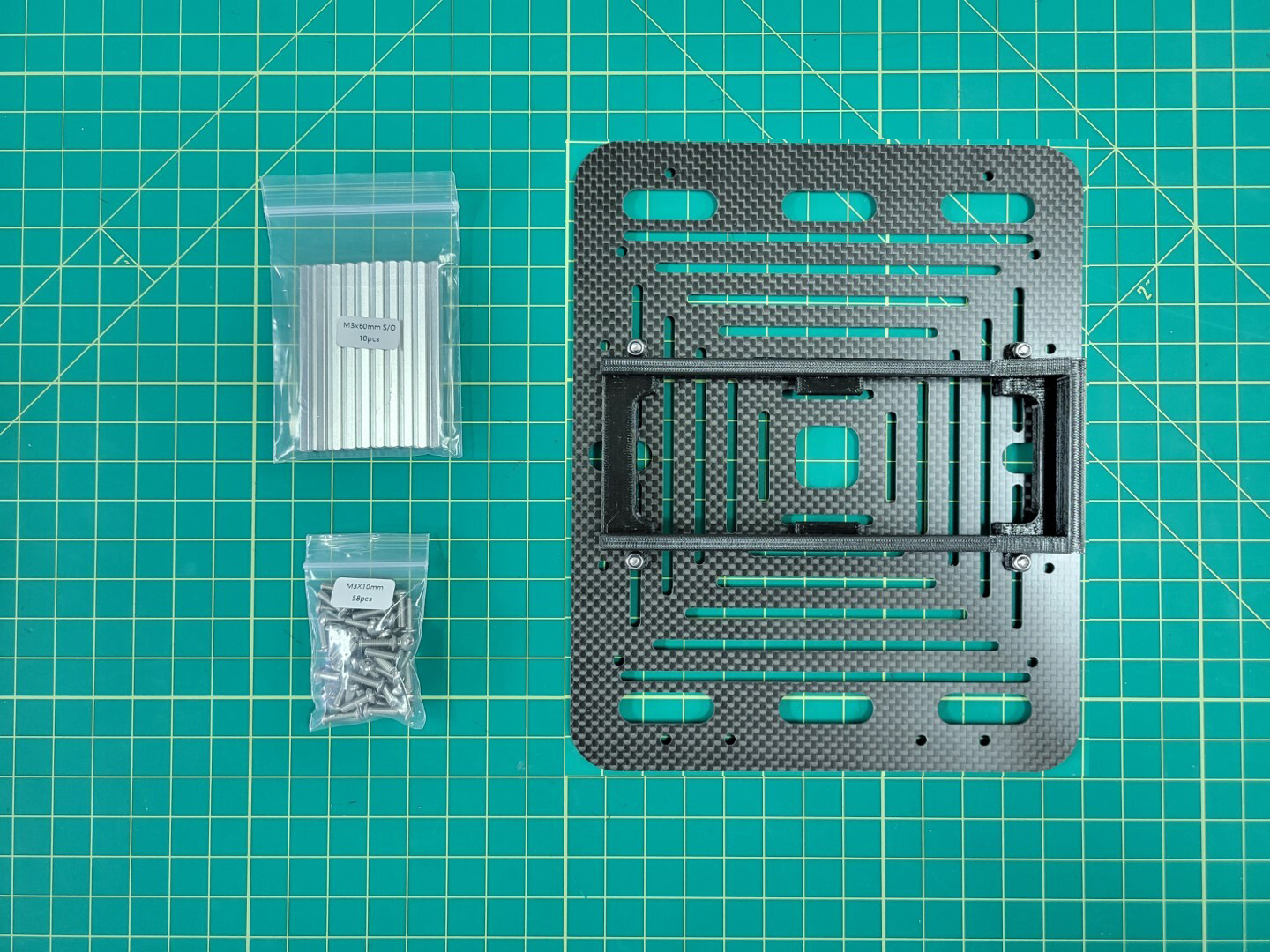
Standoff Mounting
We will be mounting the mid top plate to the bottom plate using M3x8mm standoffs and M3x6mm screws. Make sure your parts match up with the photo below.
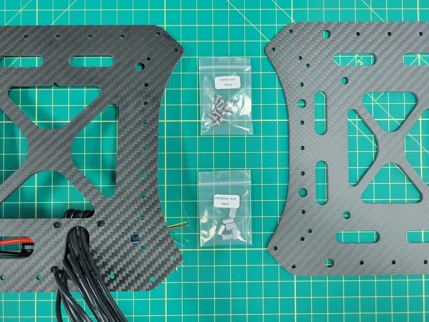
Mid plates with 8mm standoffs and 6mm M3 screws
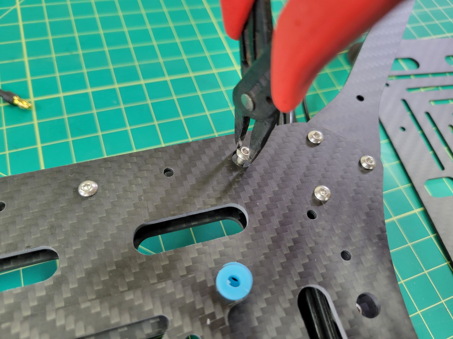
The mid bottom plate has several mounting holes around the outside edge. Locate the center hole on each edge of the plate. Place a screw in each hole.
Note
Make sure you are placing the screws through the plate on the same side as the ESC. Take a close look at the photo below for more guidance.
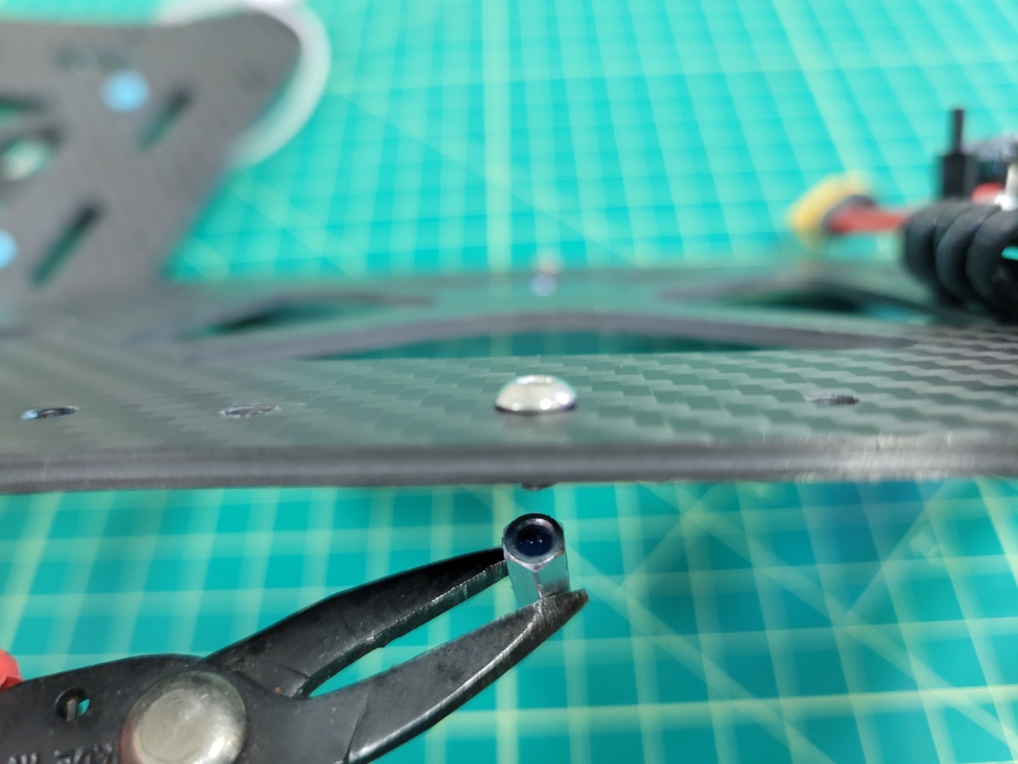
Standoff with Loctite
A small dab of Loctite in each of the standoffs will help keep the plates secure. Screw each of the standoffs into place with a 2.0mm hex driver.
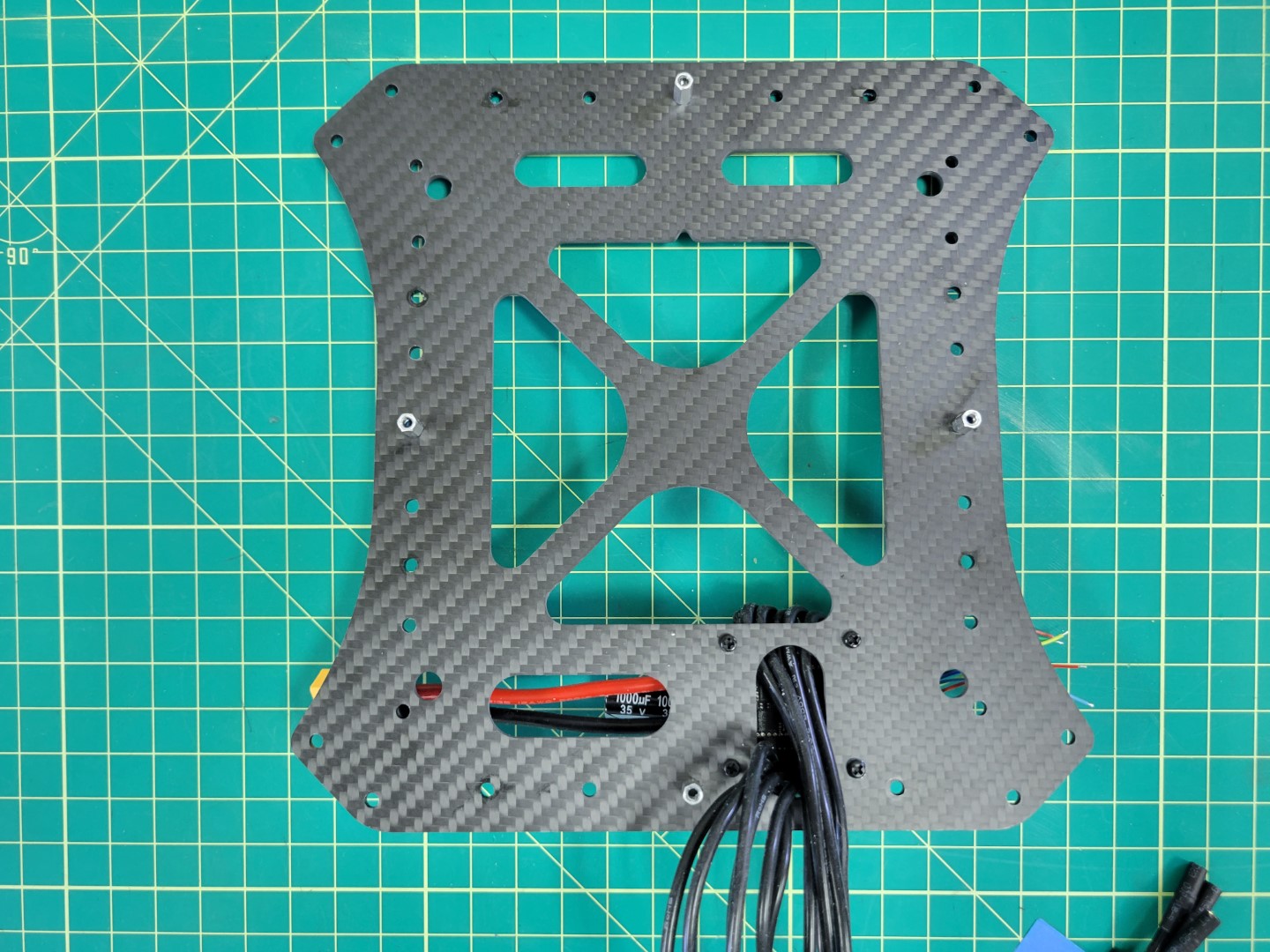
All four standoffs secured to mid bottom plate
Pixhawk FC Tray Mounting
Before securing the mid top plate we will mount the Pixhawk Flight Controller (FC) tray with four rubber dampeners. This is necessary to help isolate the FC from vibrations that are generated from the propellers.
FC tray, dampeners, and mid top plate
The following steps show installing the dampeners in the top plate first, but some prefer installing them in the tray and then attaching the tray to the top plate. Choose whatever method makes the most sense to you.
Use the same procedure as mounting the ESC dampeners. Pinch the dampener, push it into the hole, and use your 2mm hex driver to feed it through the plate. Do this for all four dampeners.
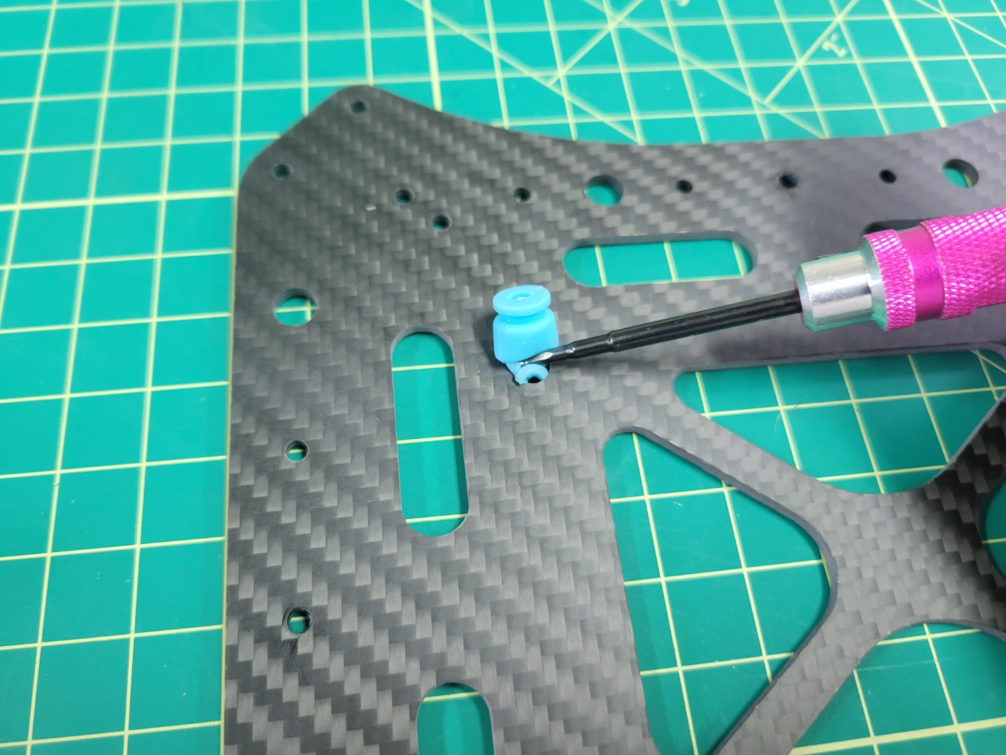
Dampener installation with 2mm hex driver
The photo below shows all four dampeners installed into the mid top plate. Proceed with installing the FC tray onto the dampeners.
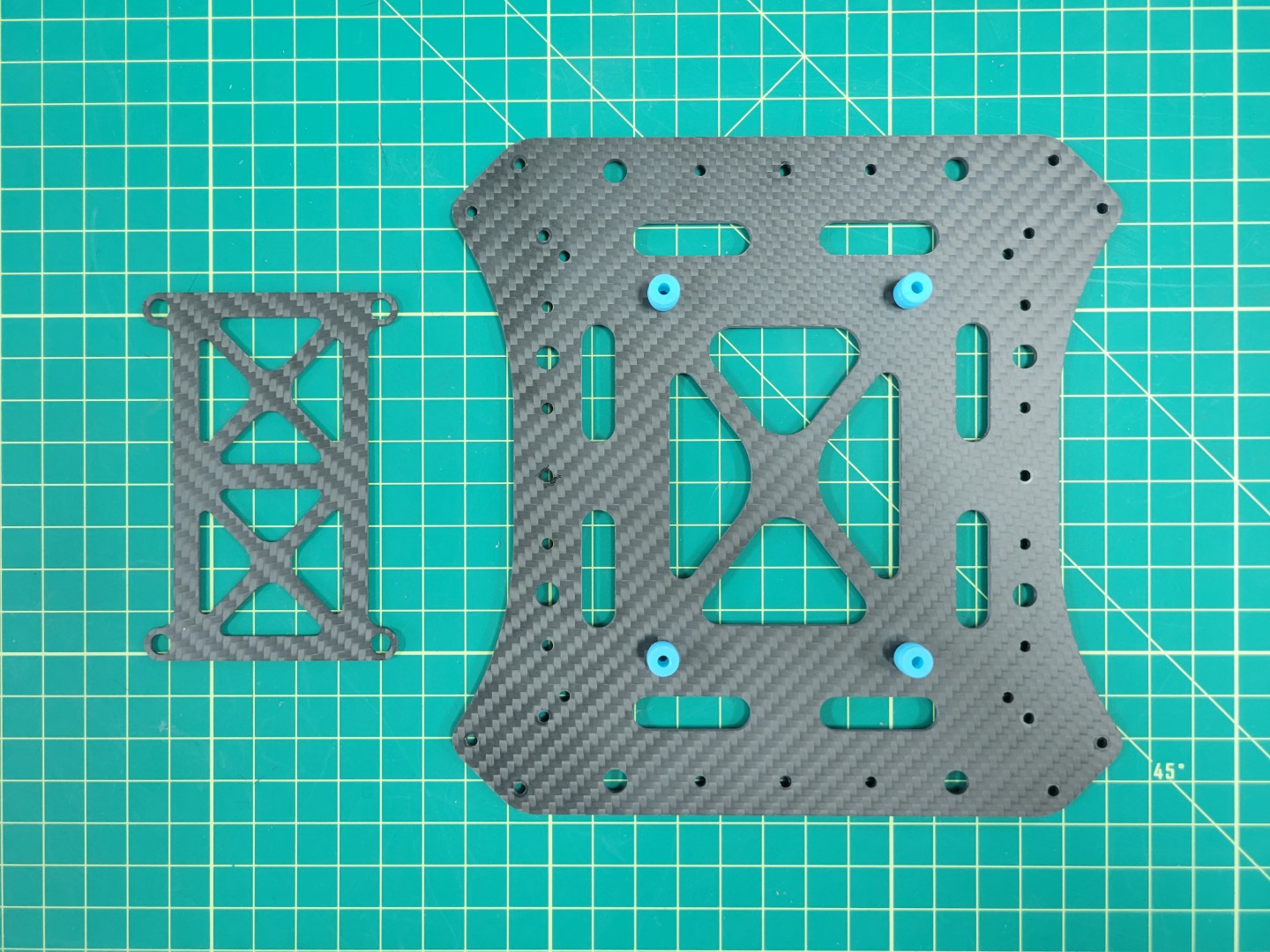
FC tray ready for installation onto dampeners
You will have limited wiggle room when installing the FC tray onto the dampeners. Be patient. In a matter of no time you will become a dampener installation pro!
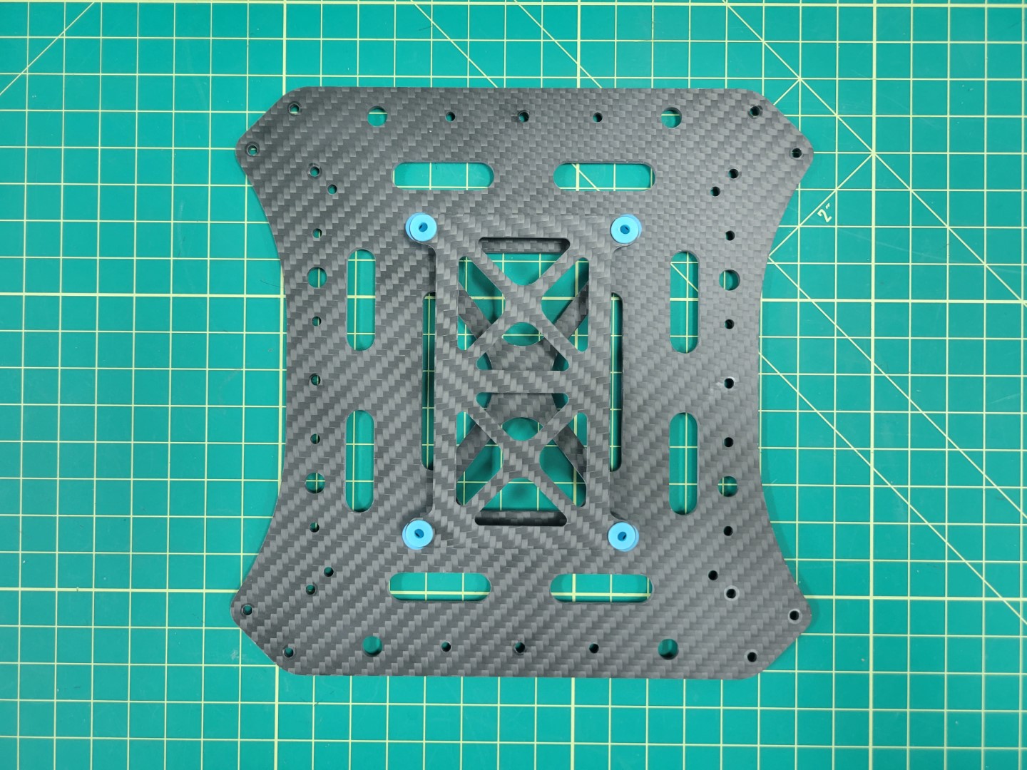
FC tray mounted onto mid top plate
Assembling Top and Bottom Plates
Place your mid top and bottom plates side by side as shown in the photo below.
Mid top and bottom plates ready to be secured
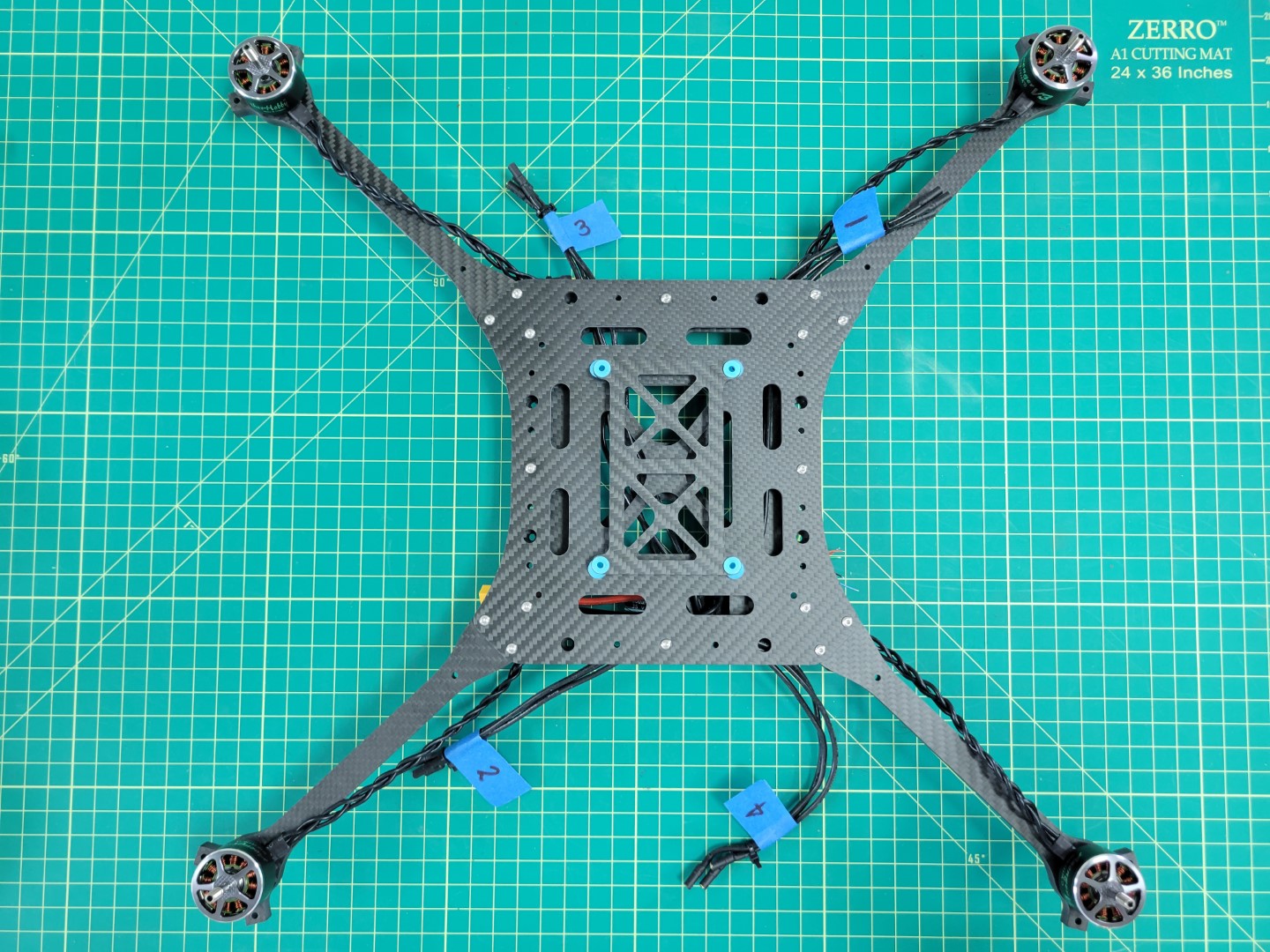
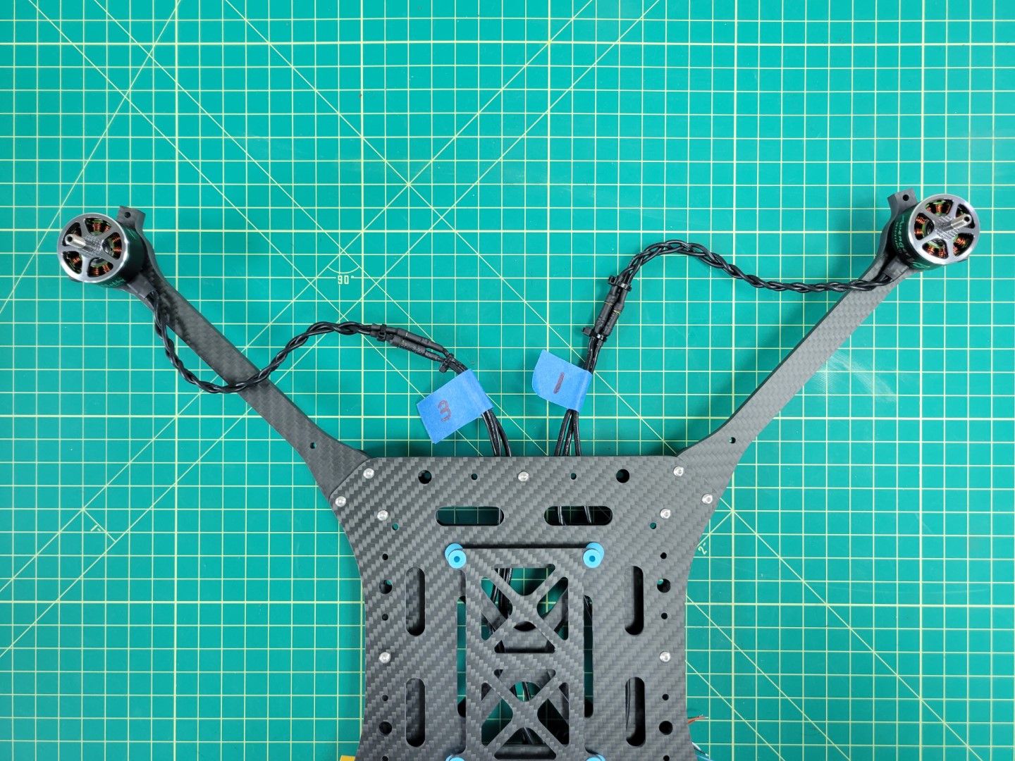
As we discussed in the previous section, motor order is incredibly important for you to have a successful flight test. Look at the motor position diagram below. Lay out each of your ESC leads in this same order.
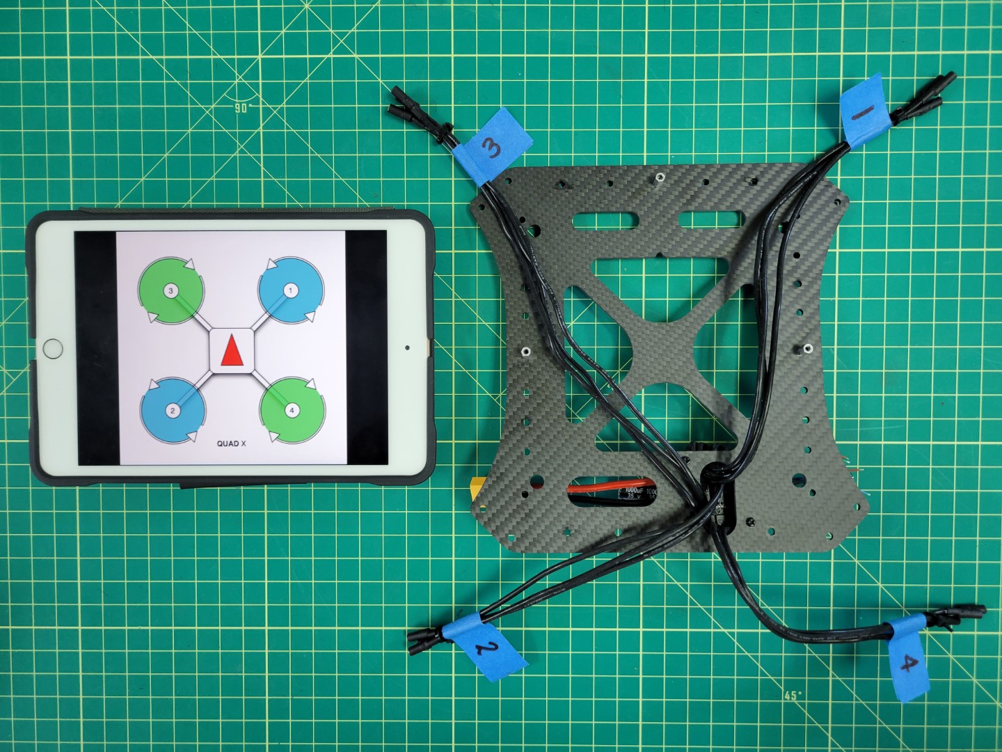
Matching up ESCs with their motor position
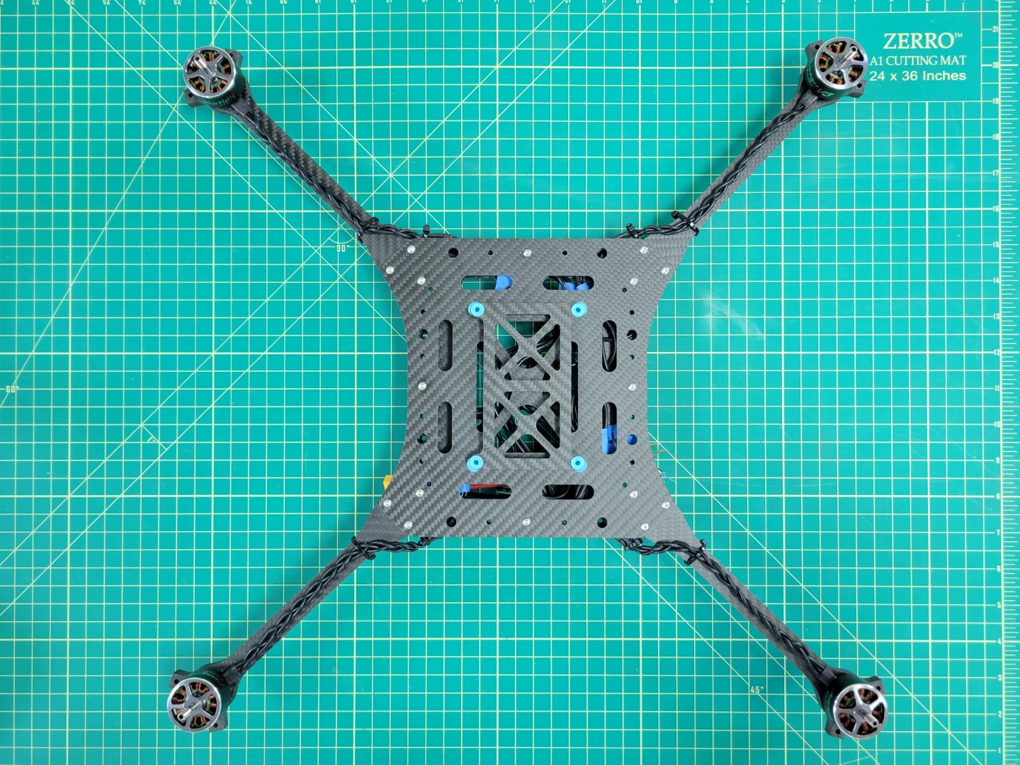
Place Loctite in each of the standoffs and secure the mid top plate with four 6mm screws. Your mid plate assembly is now complete!
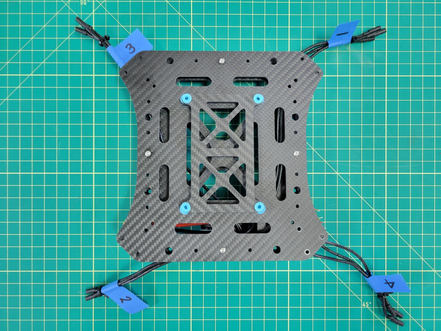
Completed mid plate assembly
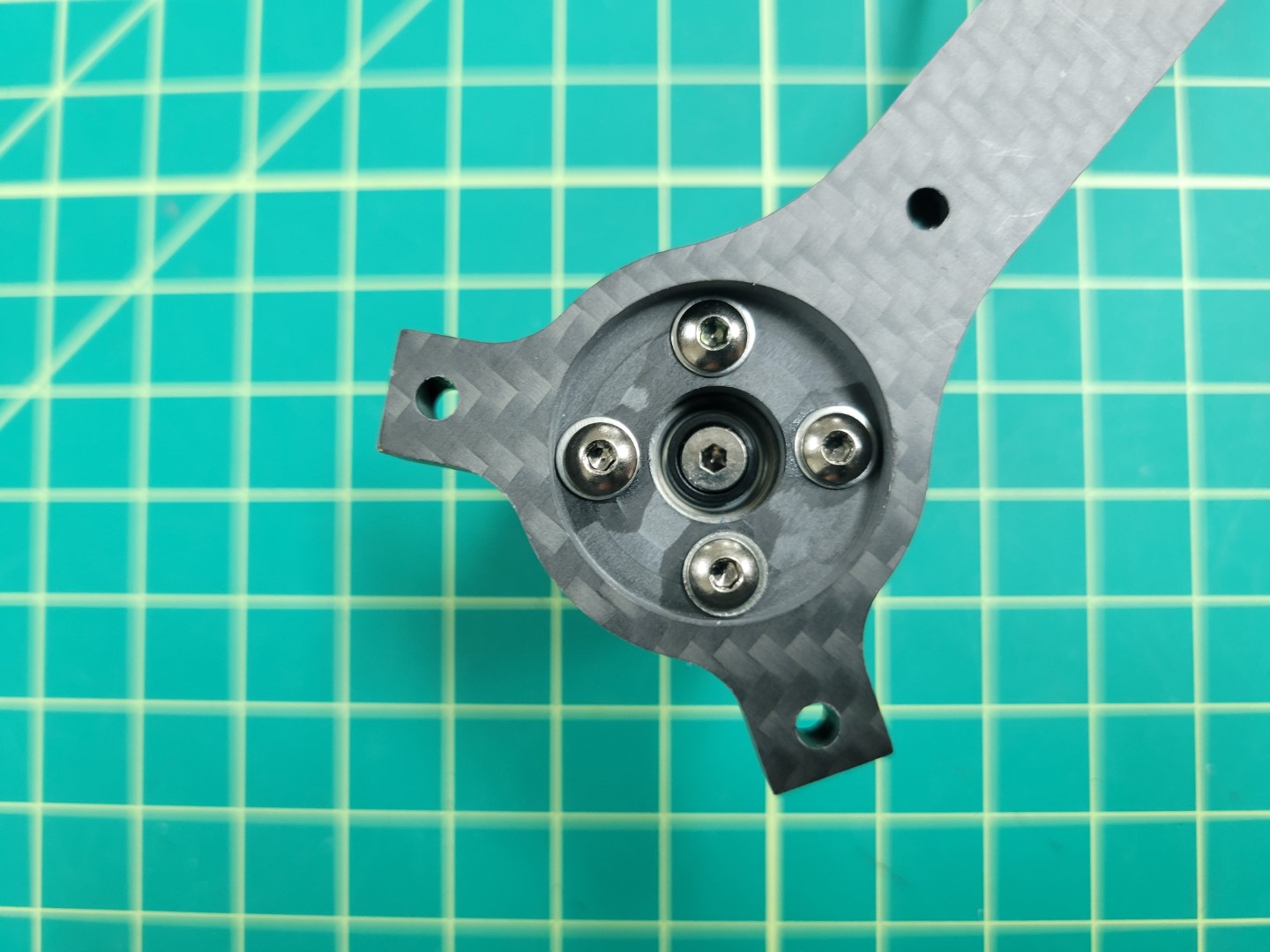
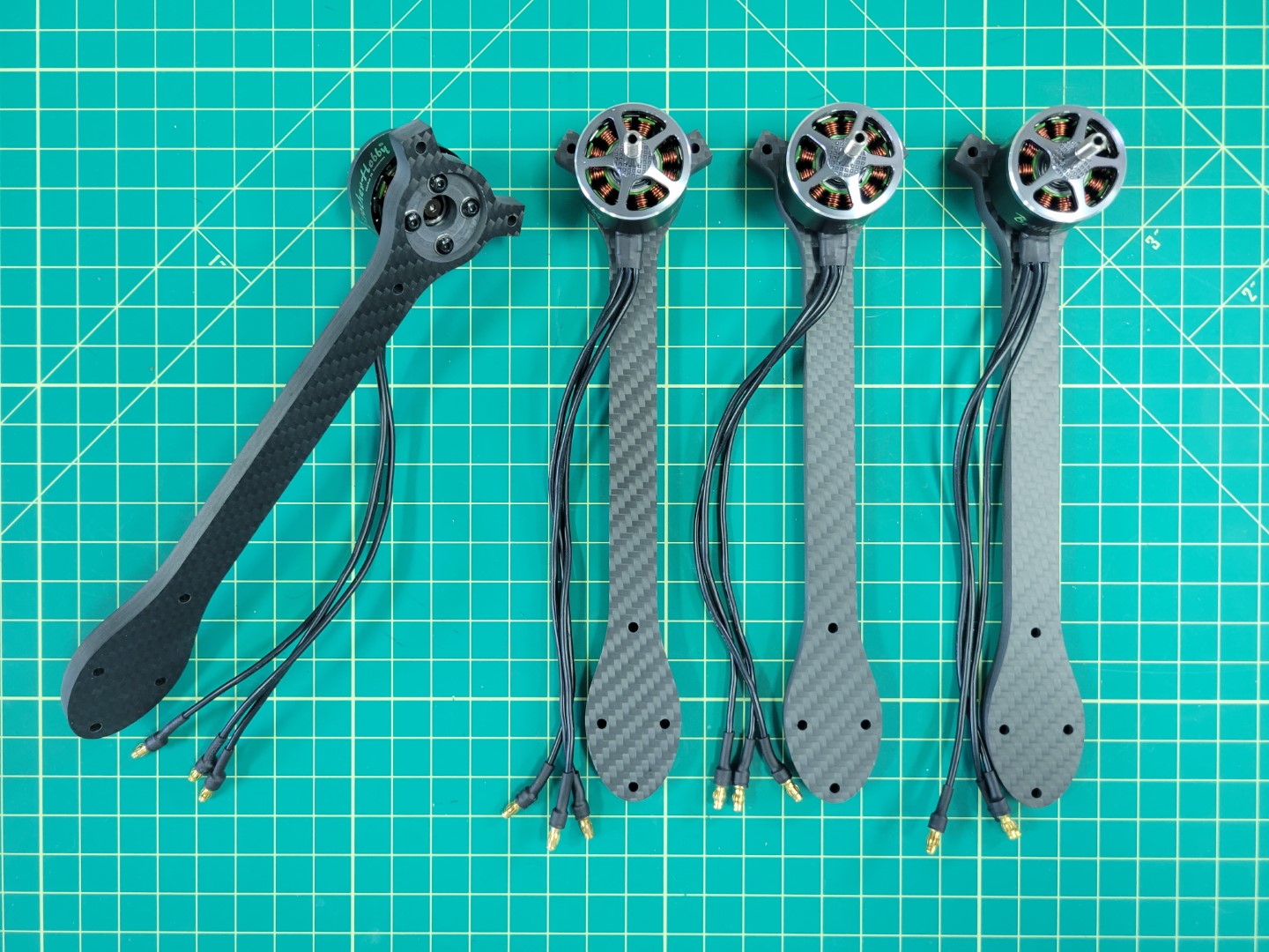
4.3 - Motors and Arms
In this section we will walk through the process of mounting the drone motors to the arms of the frame
Overview
Motor position and rotation are incredibly important for any drone to fly properly. In your kit you will notice two motor boxes labeled CW (clockwise) and two CCW (counter clockwise). This represents the direction of rotation for each motor. Let’s revisit motor position and rotation in the image below:

PX4 motor position and rotation
Motor positions 1 and 2 require CCW rotating motors and motor positions 3 and 4 require CW rotating motors.
You may be wondering how to determine the rotation of each motor. There are two ways to determine this. The first, and less intuitive in our opinion, is to look at the motor can. The photo below shows the motor size (2812) and kV rating (900) printed in two different formats. The kV rating for the CCW rotating motor is printed before the motor size. The kV rating for the CW rotating motor is printed after the motor size.
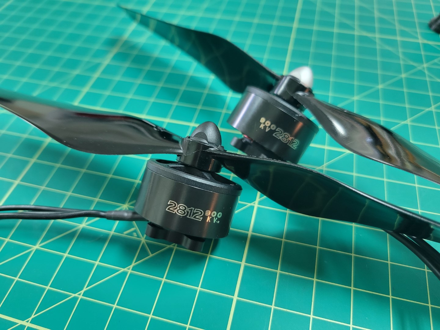
CW (black cap) and CCW (silver cap) motors
With that out of the way let’s cover a much more intutive (in our opinion) way to determine motor rotation. It requires using the propellers included in your kit. The silver capped propeller is a CCW rotating propeller and is threaded in a way that it will only screw onto the CCW motors. The black capped propeller is a CW rotating propeller. It is threaded in a way that it will only screw onto the CW rotating motors.
The photo below shows an example of installing a CW rotating propeller. Hold the propeller in place and rotate the motor in a clockwise direction. If the thread pattern is correct the propeller will screw onto the motor shaft and lock into place.
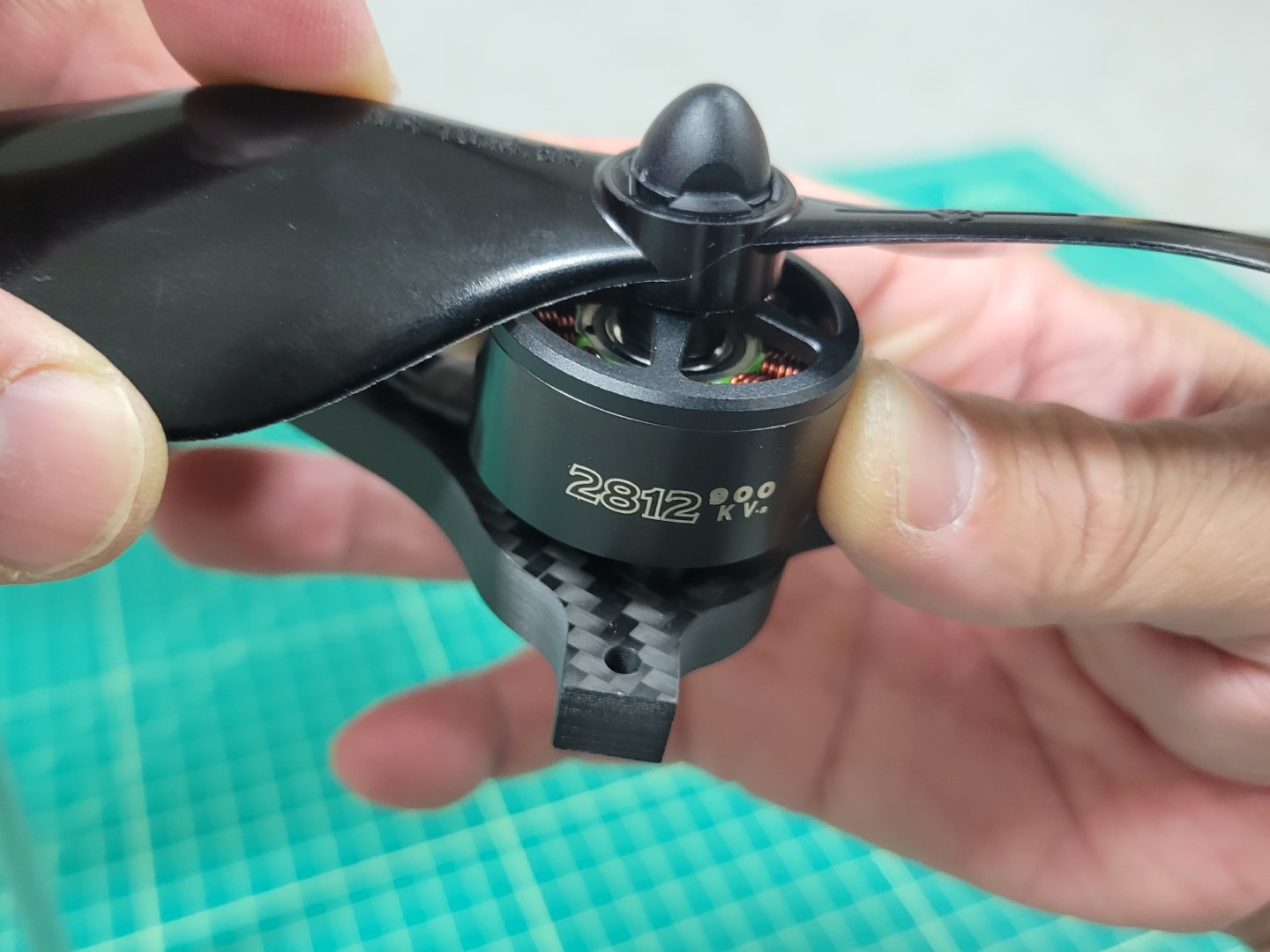
CW propeller mounting
Repeat this process for each of the four motors and then use tape to label them, just like you did with your ESC leads. You will be glad you did later!
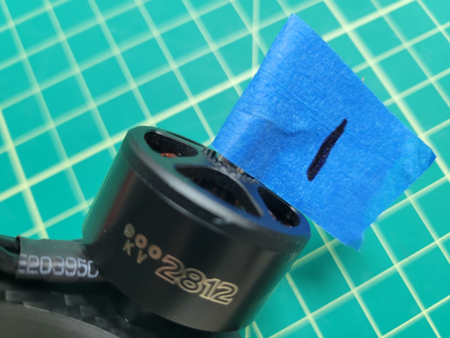
Label each of your four motors
You should have the following:
- Motor 1: CCW
- Motor 2: CCW
- Motor 3: CW
- Motor 4: CW
Attaching Motors to Arms
Inside each motor box there is a small ziploc bag of 4 x 8mm screws. In your AVR kit you will also find a ziploc bag of M3 washers.
Warning
Please be sure to use the screws provided in the small ziploc bag inside the motor box. Using longer screws from the kit can end up damaging the motor windings and ultimately prevent the motor from operating.
The photo below shows the necessary parts for mounting the motor to the frame arm. You will follow this procedure for each of the four motor/arm assemblies.
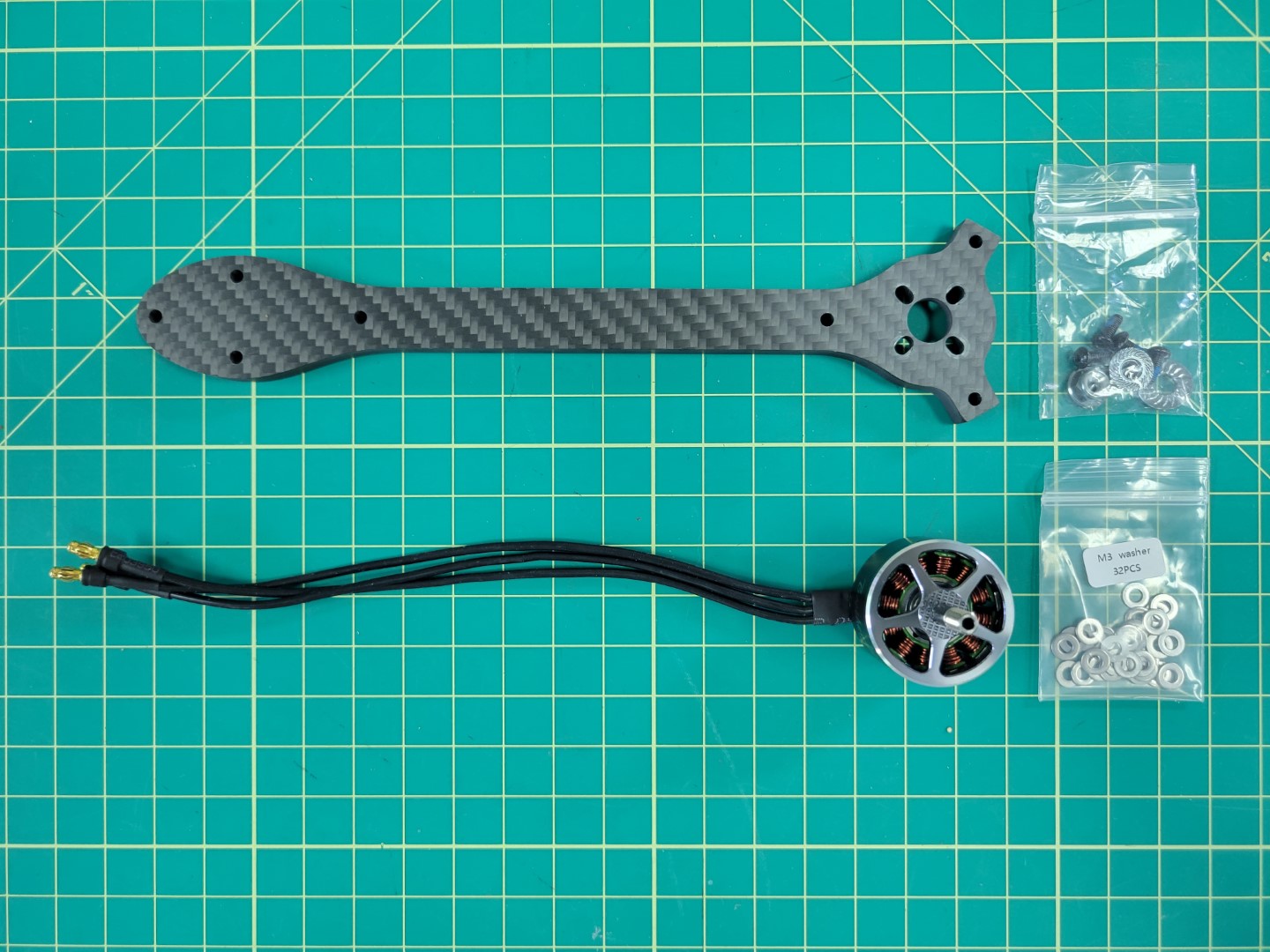
Parts necessary for mounting each motor
A 2mm hex driver is necessary to secure each of the 8mm screws into the motor.
Warning
Don’t forget to use one M3 washer with each screw. This will help reduce stress on the carbon fiber arm.
Place a small drop of blue Loctite on each screw as shown in the photo below.
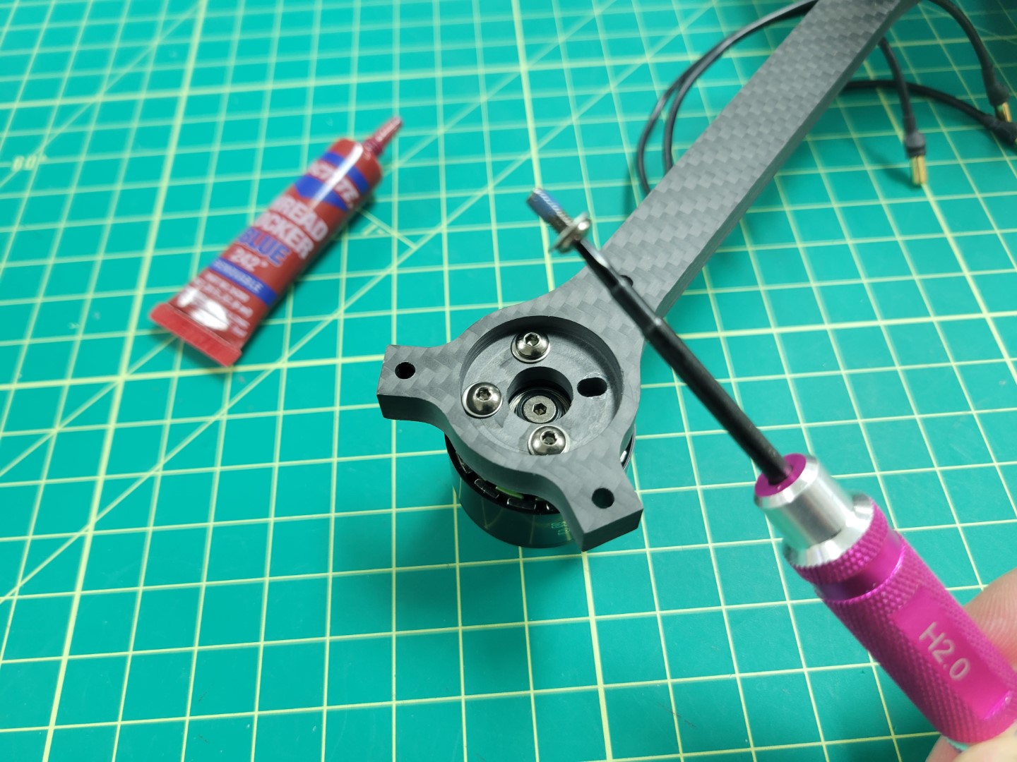
Blue Loctite on motor screw
Loctite is useful in helping secure your screws and prevents them from coming loose.
Motor mounted and secured
Repeat this process for all four of the motors.
All four motor/arm assemblies complete
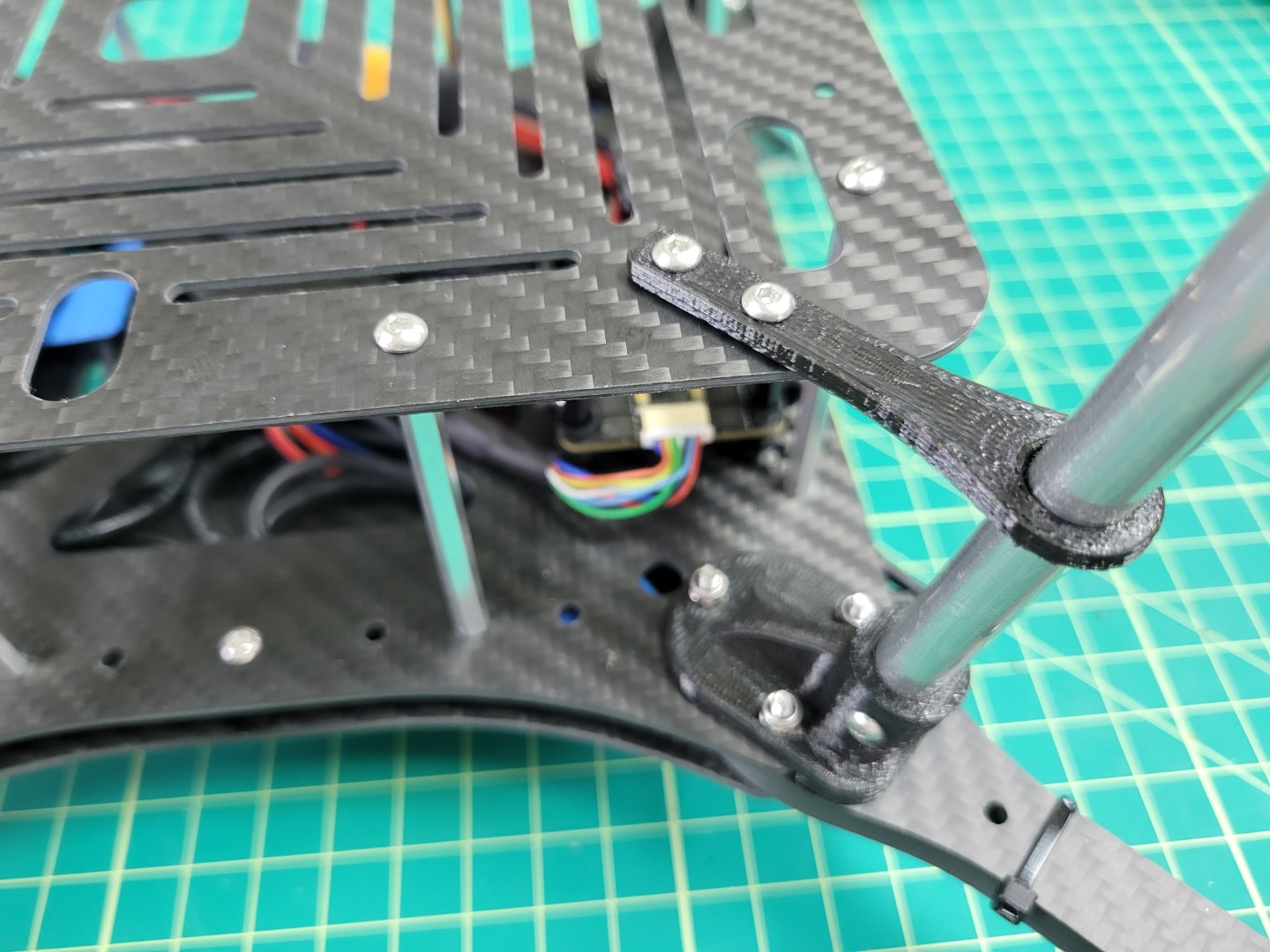
Attaching Arms to Midplate
Note
To proceed with this step you must 3D print four landing gear mounts. Make sure to print with 100% infill as these mounts will experience a lot of stress from the weight of the drone and hard landings.
Locate the M3 22mm screws and lock nuts in your AVR kit. These will be necessary for mounting the motor arms to the midplate and securing the 3D printed landing gear mount.
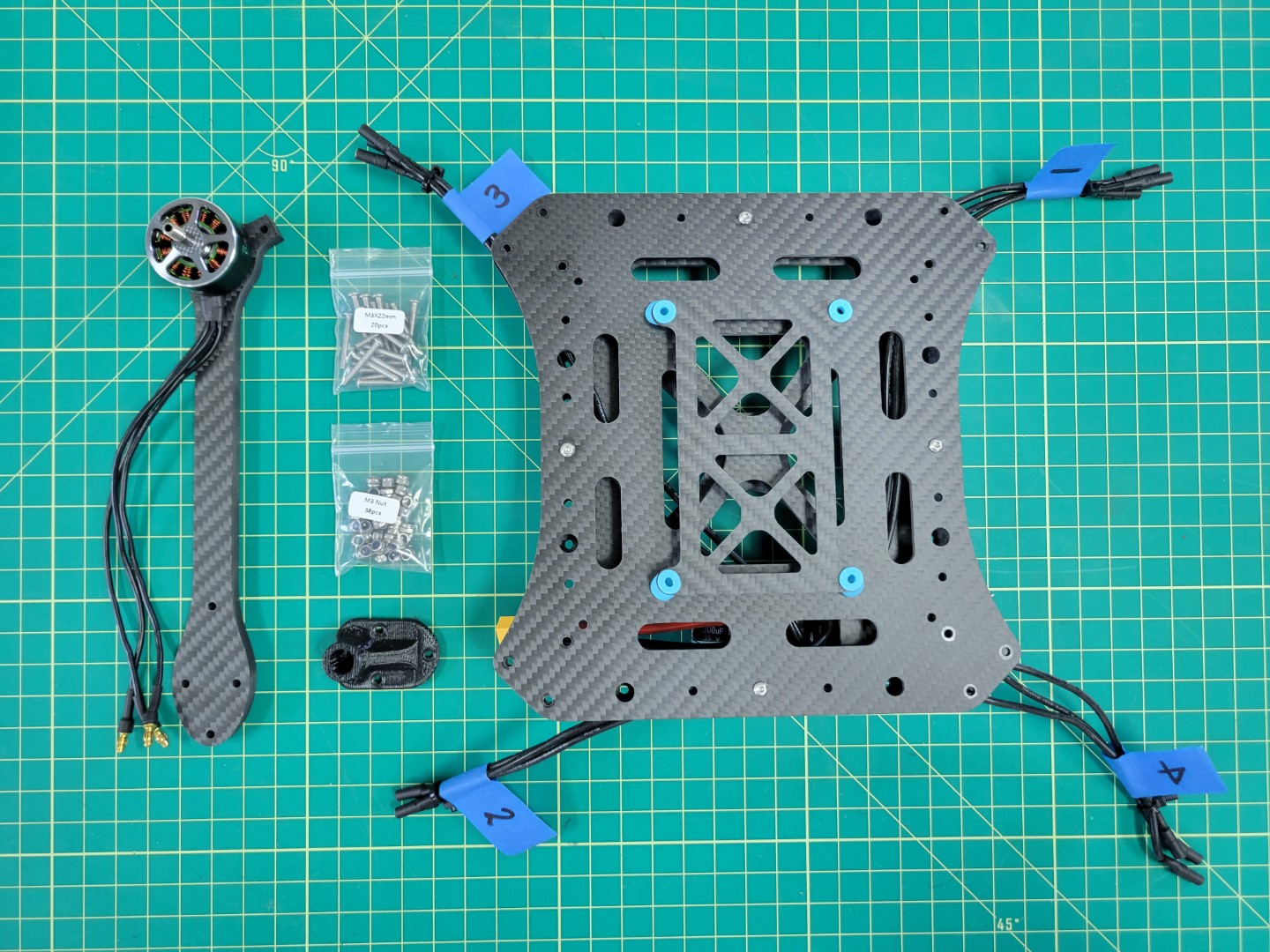
Parts for motor arm mounting
Each arm will require three 22mm screws and lock nuts. You will insert each of the screws through the top plate, arm, bottom plate, and landing gear mount. The lock nut will be secured from the bottom as shown in the photo below. A 5.5mm box driver is necessary for tightening the nut. Be sure to tighten each nut securely.
Tip
Save yourself some trouble and make sure that the motor arms are mounted in the right position. Make sure that the labeled ESC leads match with the motor labels. Refer back to the PX4 motor image above if necessary.
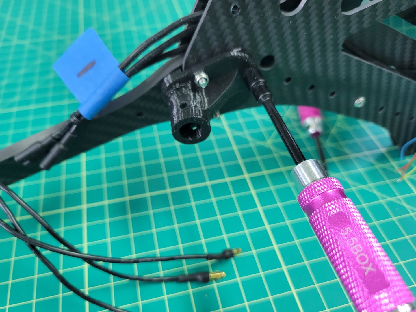
Securing lock nuts with 5.5mm driver
Repeat the installation process for each motor arm.
All four motor arms secured
Flip your AVR drone over and connect each of the motor leads to the corresponding ESC leads.
Motors and ESCs ready to be connected
Be sure to make a good connection between the male leads of the motor to the female leads of the ESC. You should not see any brass between each of the connections. This is important so that nothing comes loose or causes a potential short.
Motors and ESCs all wired up
Feed any excess cable slack between the top and bottom plates. You can use zip ties to clean up your cabling as shown in the photo below.
Zip ties keep you build nice and tidy
Motor position and rotation is an important part of any drone build. The photo below is a gentle reminder. It won’t be long before you have this photo memorized!
Motor position and rotation
4.4 - FC to ESC Wiring
We will walk through creating the FC and ESC cable
FC Wiring
Note
This section of the build requires some additional tools not included in your AVR kit such as a soldering iron, heat shrink tubing, wire strippers, and a hobby knife.
You may have noticed that the ESC has a connector with several flying leads coming out of it. These leads are what we will be connecting to the FC. The FC will send PWM (Pulse Width Modulation) signals to each of the motors to keep the AVR drone hovering in the air.
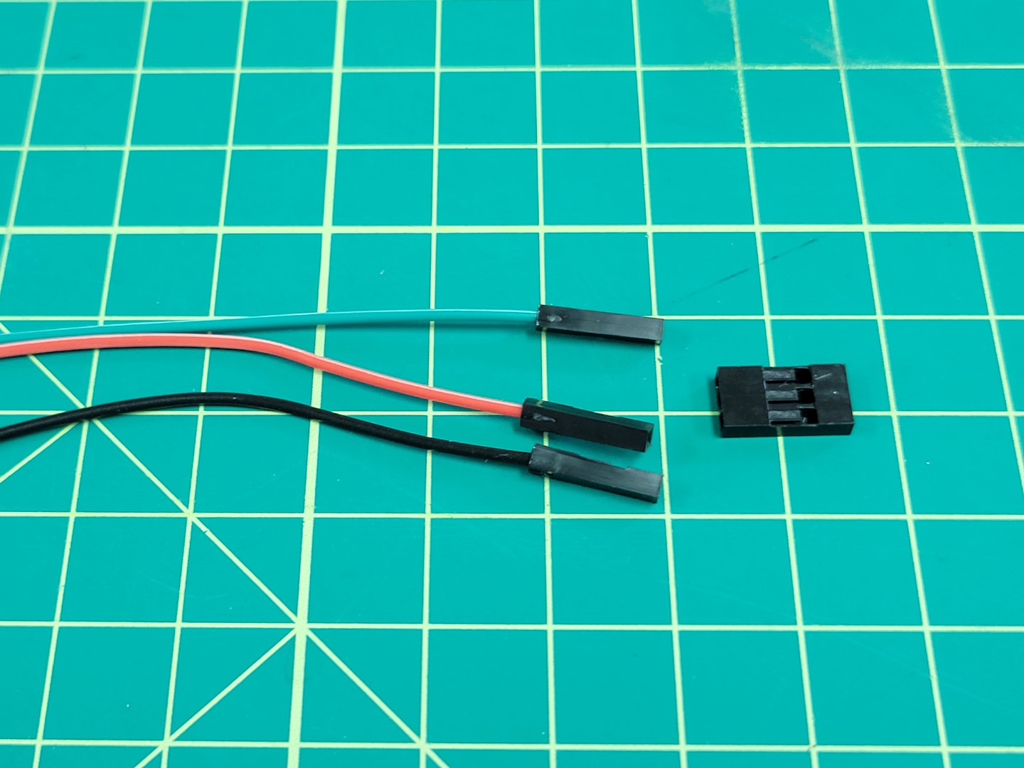
Remove the small white cable adapter from the ESC and gather the necessary parts for this phase of the build as seen in the photo below.
Parts for wiring FC to ESC
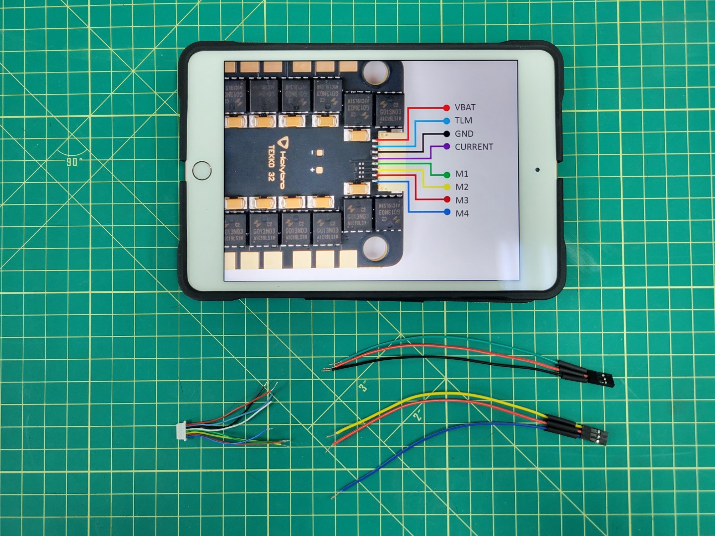
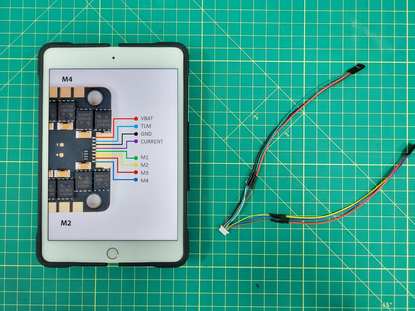
The image below shows the pinout for the ESC connector. We will be focused on wiring each of the motor leads (M1-M4) as well as VBAT and GND to the PWM module of the FC. We will not be using TLM or CURRENT.
Warning
Each of the leads has a small amount of wire exposed. Go ahead and clip off the exposed wire of the TLM and CURRENT leads.
Pull out four jumper cables from your AVR kit and to keep things simple make sure they mach up with each of the motor wire colors. They will be green (M1), yellow (M2), red (M3), and blue (M4) as seen in the image below.
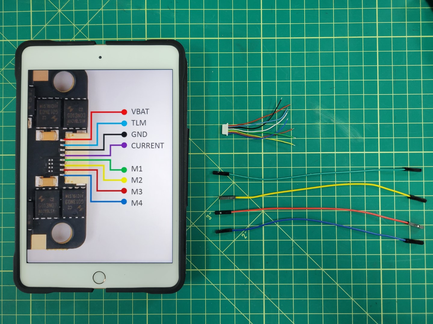
Laying out wires for soldering
Remove the plastic female connector from one end of each jumper cable. This is easy to do once you understand how the connector works. There is a small tab that you can pry up and then slide the cable out. A small flat head screwdriver or tweezers area great tools to assist with this step.
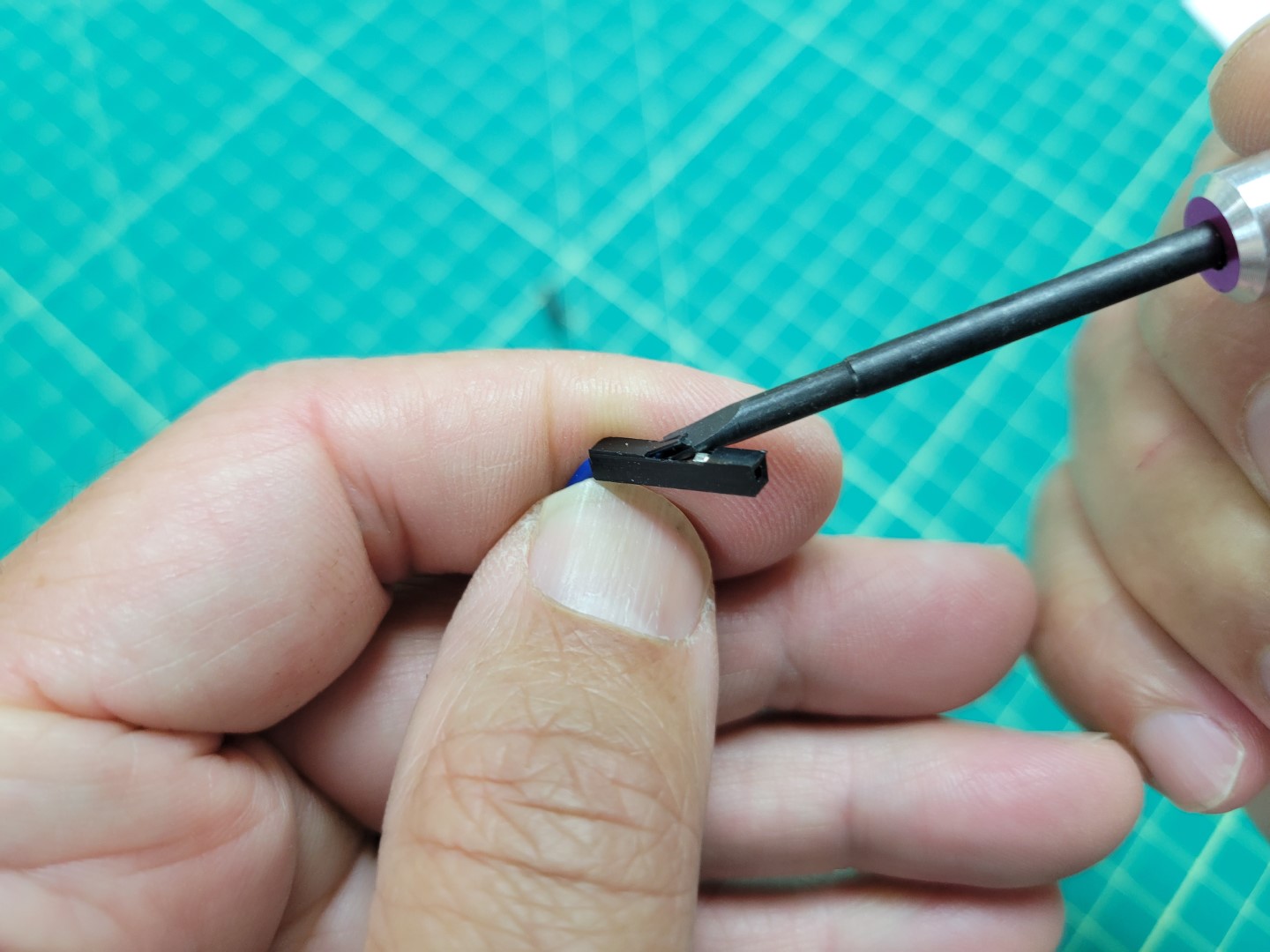
Plastic connector with tab lifted up
Slide the wire all the way out and get rid of the plastic connector.
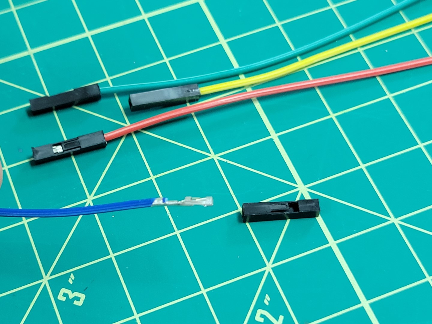
Wire removed from plastic connector
Slide the wire into the servo connector housing as shown in the photo below. Servo connectors can be found in a small envelope of miscellaneous parts in your kit. Refer back to the first photo in this section to see it.
Note
Make sure that you listen for a click sound when sliding the wire into the servo connetor. Pay attention to the orientation of the wire in the photo below. When the wire is secure you can lightly pull on it and it will not come out.
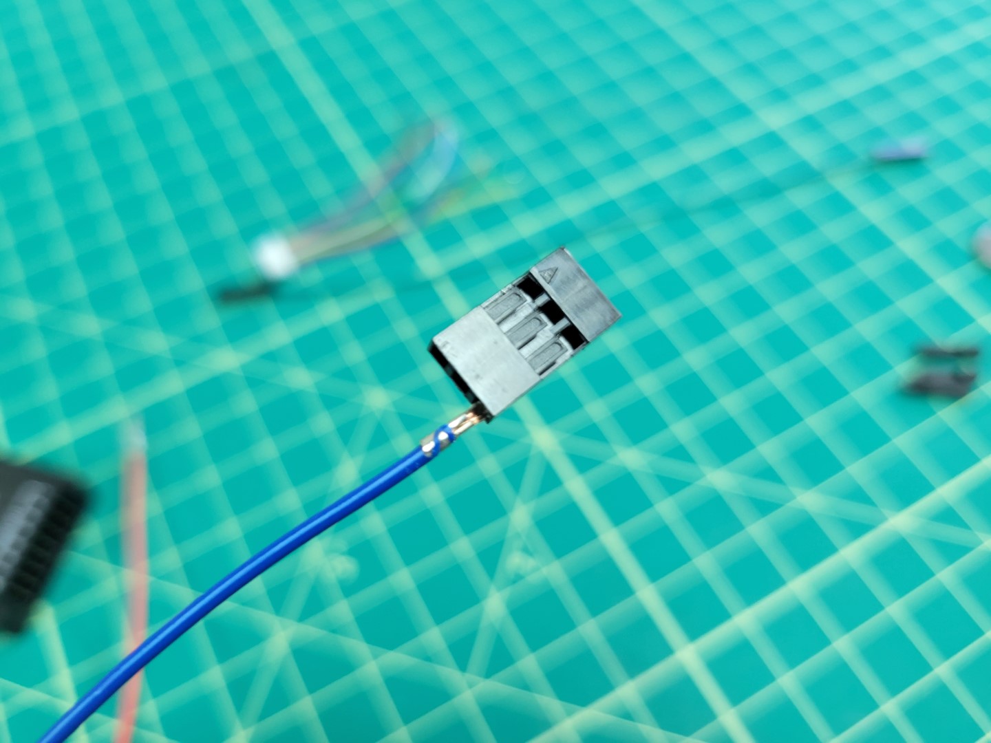
Sliding wire into servo connector
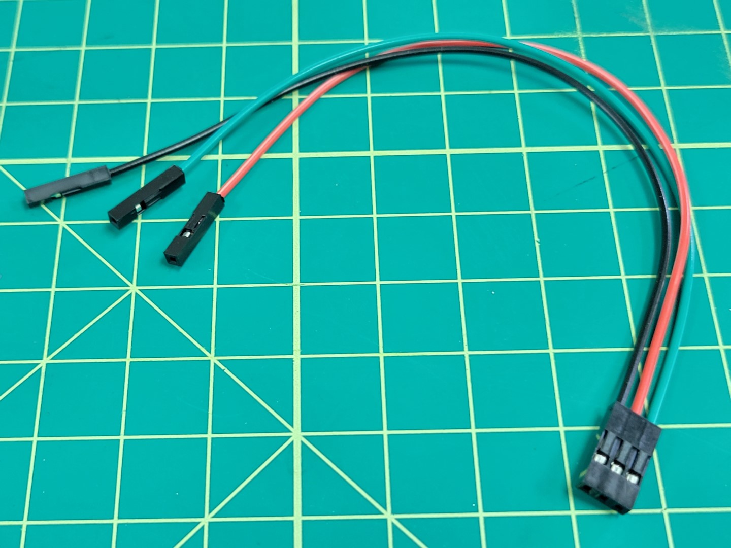
The blue wire is now secured into the connector and represents motor #4 (M4).
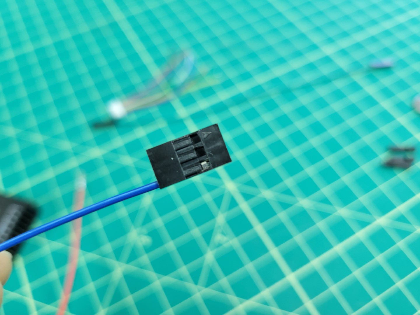
M4 wire securely in place
We will repeat this step for M2 (yellow wire) and M3 (red wire).
Warning
Motor order is incredibly important! Pay close attention to make sure your wire colors correspond with the correct motors.
The photo below shows how the cable will be attached to the PWM module from the Pixhawk. You will notice that the connector is plugged in horizontally across the top row of pins 2, 3, and 4. Pixhawk can support up to 8 motors (an octocopter) and each number represents a specific motor.
Tip
If you look closely at the PWM module you will see S, +, - labeled on the right side. This means the top row of pins are SIGNAL pins, the middle are POWER pins, and the bottom are GROUND pins.
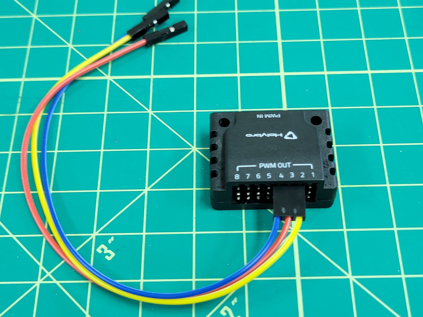
M2, M3, and M4 connector
Let’s repeat the same process for M1 (green), VBAT (red), and GND (black). You will remove each of the plastic female connectors and secure the wires into the servo connector.
M1, VBAT, and GND wires
Once again, pay attention to the ordering of your wires. Your second cable should look identical to the one below.
M1, VBAT, and GND in servo connector
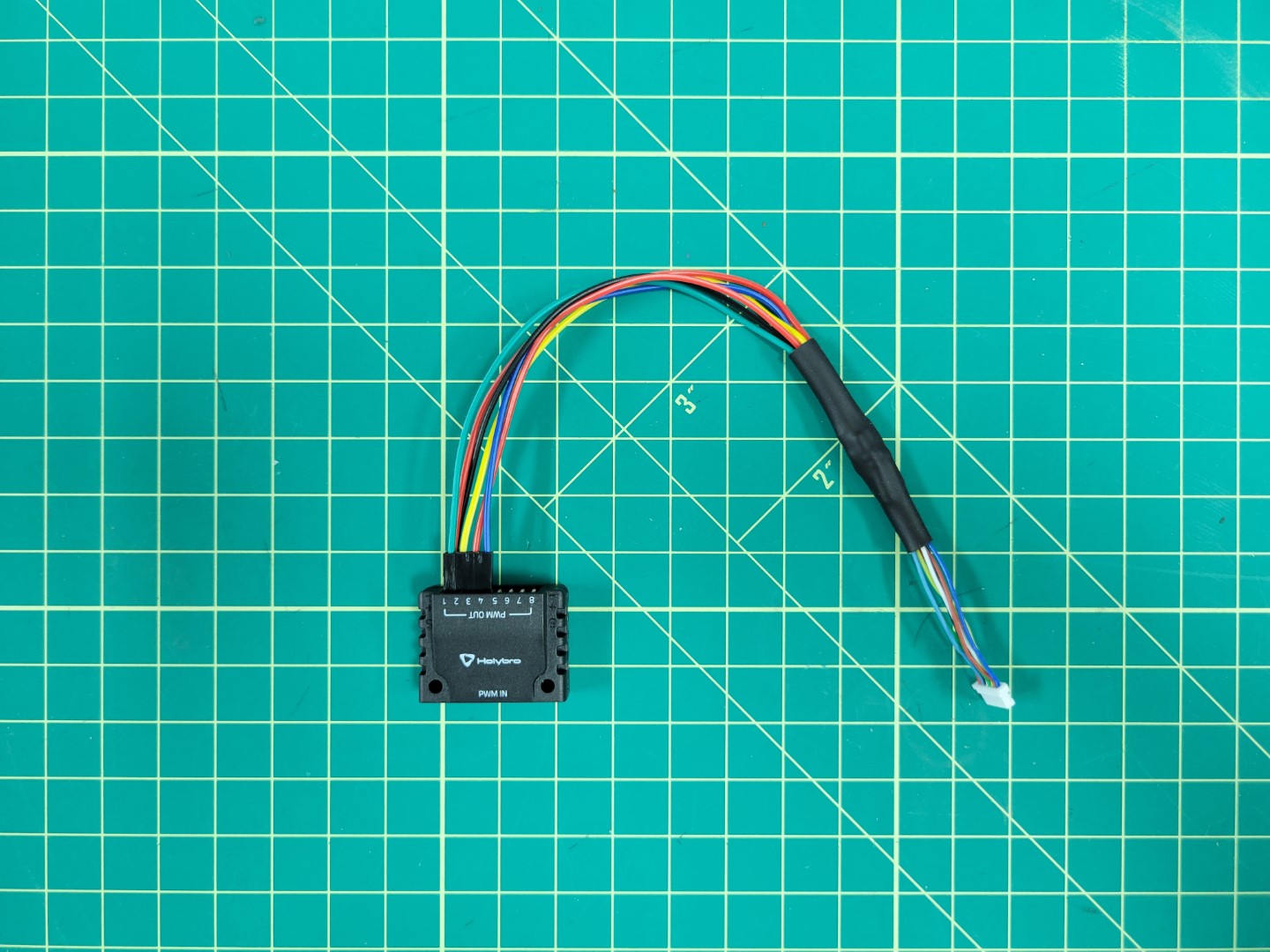
Make sure your cables are plugged into the PWM module as shown below.
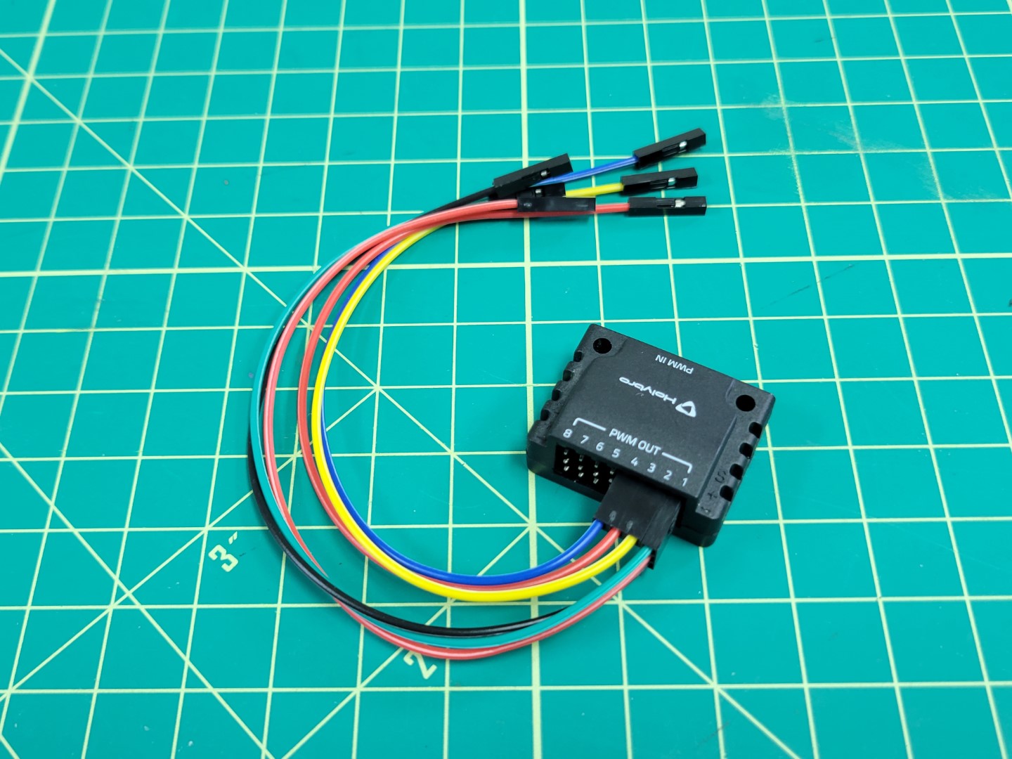
PWM module wired up
Here is a close up of the connections. This represents the FC side of the wiring. Now we will proceed with the ESC side.
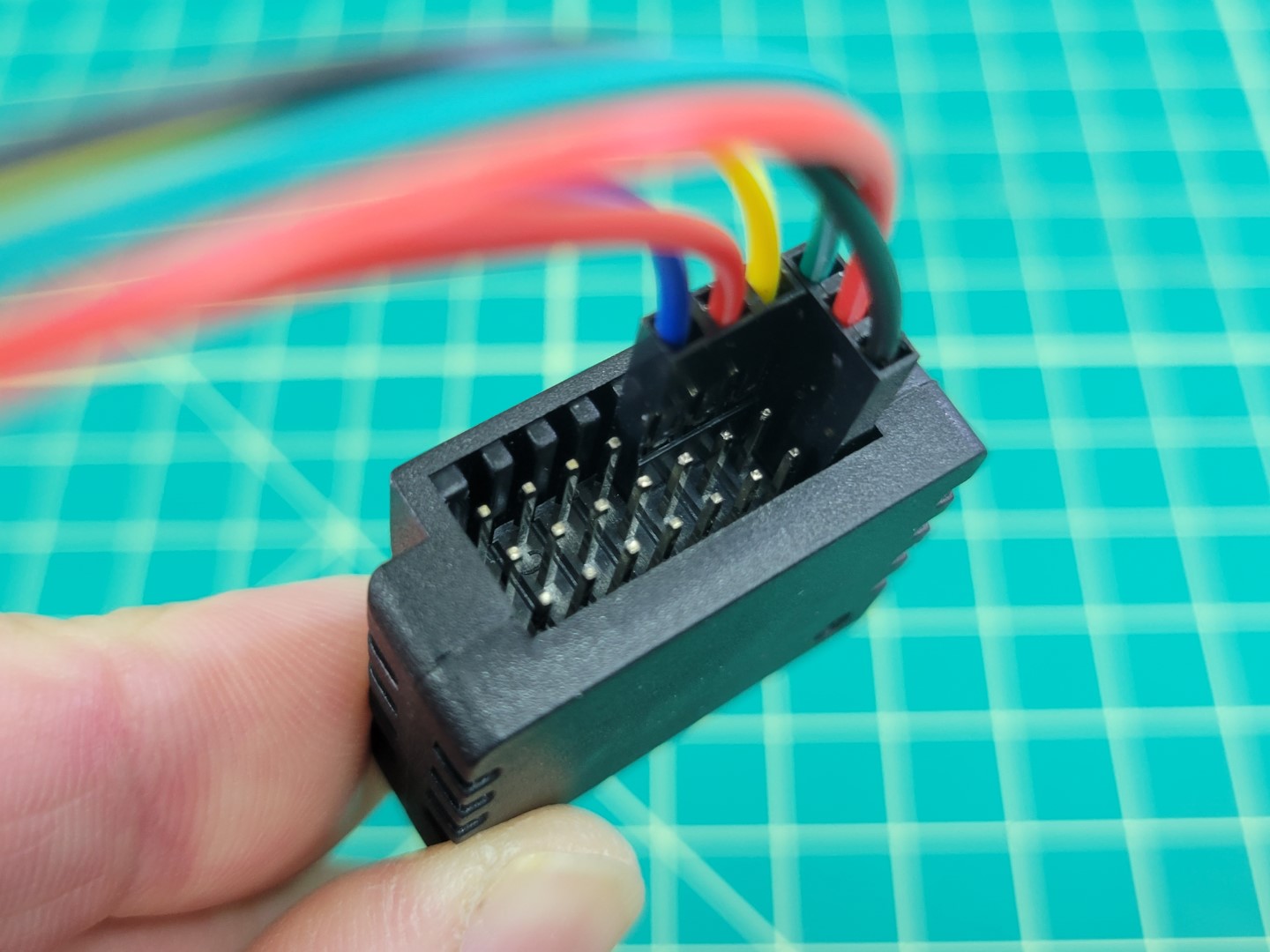
PWM module close up
ESC Wiring
Go ahead and unplug your cables from the PWM module. Let’s take one last look at the ESC side connections before we solder.
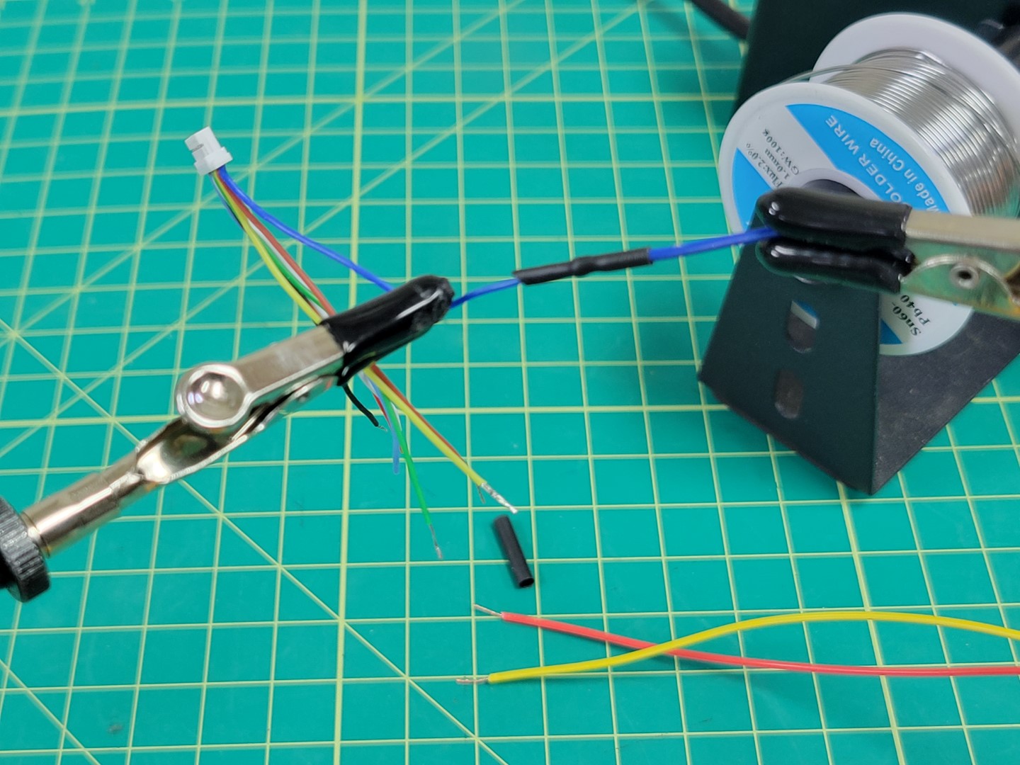
Use wire cutters to cut off the plastic female connectors from the other end of the colored leads. Proceed with stripping off about 1/2" of the wire insulation.
Remove about 1/2" of insulation from the ESC leads. You will notice that the ESC leads already have some wire exposed.
Tip
The ESC leads are very thin. We have found it easiest to pinch with your fingernails and pull the insulation away. Use caution as you do not a lot of spare wire on the ESC side!
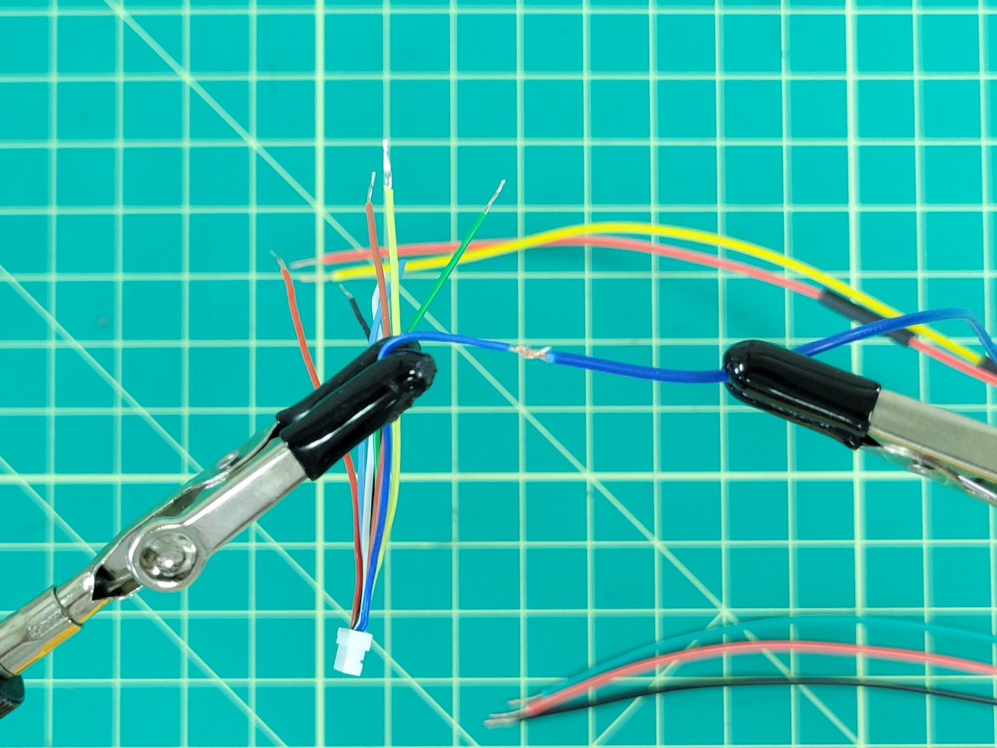
Match up the wire color on the FC side with the same color on the ESC side. Twist the wires together using the “Twisted Helix” method described in the video below.
Warning
Don’t forget to add heat shrink tubing before twisting your wires together! The heat shrink will be necessary to keep the connections from shorting after you solder.
The photo below shows the blue M4 wire from the ESC connected to the M4 wire of the FC. The wires are secured using the “Twisted Helix” method.
Wires twisted and ready for soldering
Tip
A helping hands device makes the soldering process 100x easier. Whatever method you use take care not to pierce the insulation of the wires. You can see in the photo below our alligator clips are covered with rubber shields.
Place solder all around the joint to strengthen the connection.
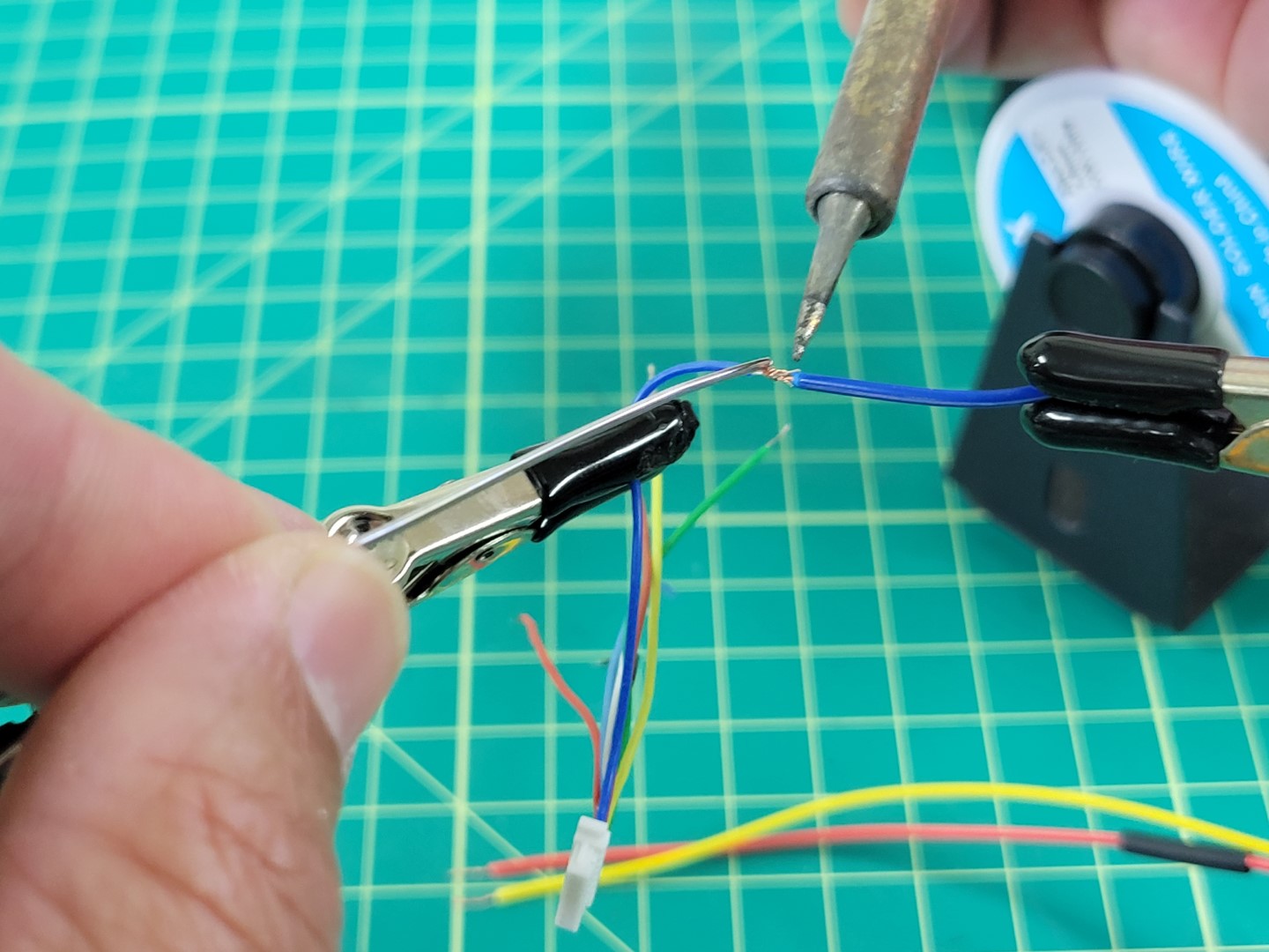
Soldering the ESC and FC M4 wires together
A little solder will go a long way. Don’t overdo it as you will need to slide the heat shrink over the joint next.
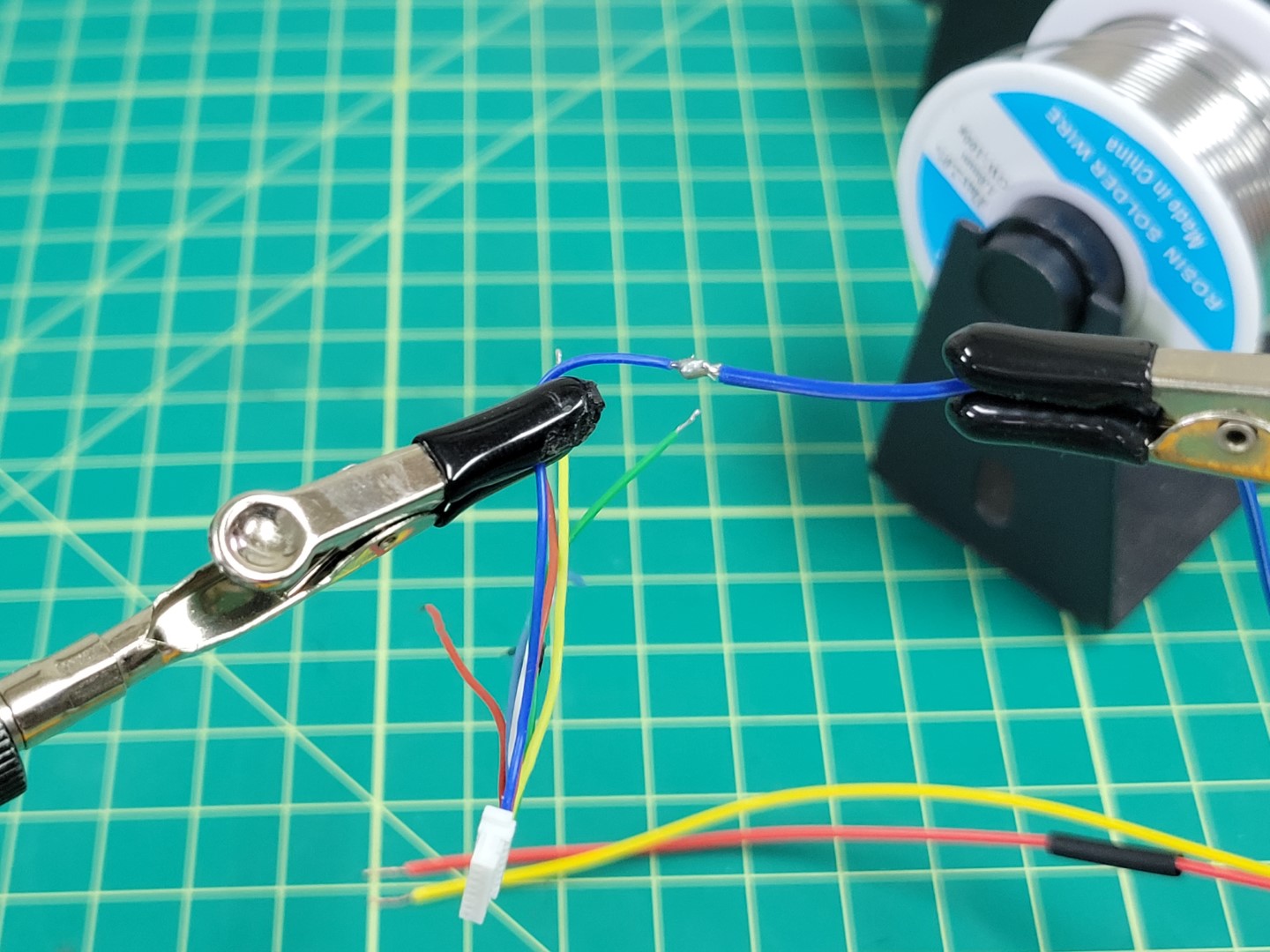
M4 wires soldered together
Slide the heat shrink over the connection and apply heat to it using a heat gun or a lighter.
Heat shrink applied to M4 wire
Repeat this process for the M2 (yellow) and M3 (red) wires.
Warning
Red wire was used for both M3 and VBAT. Make sure not to get these wires mixed up!
M2, M3, and M4 wires soldered
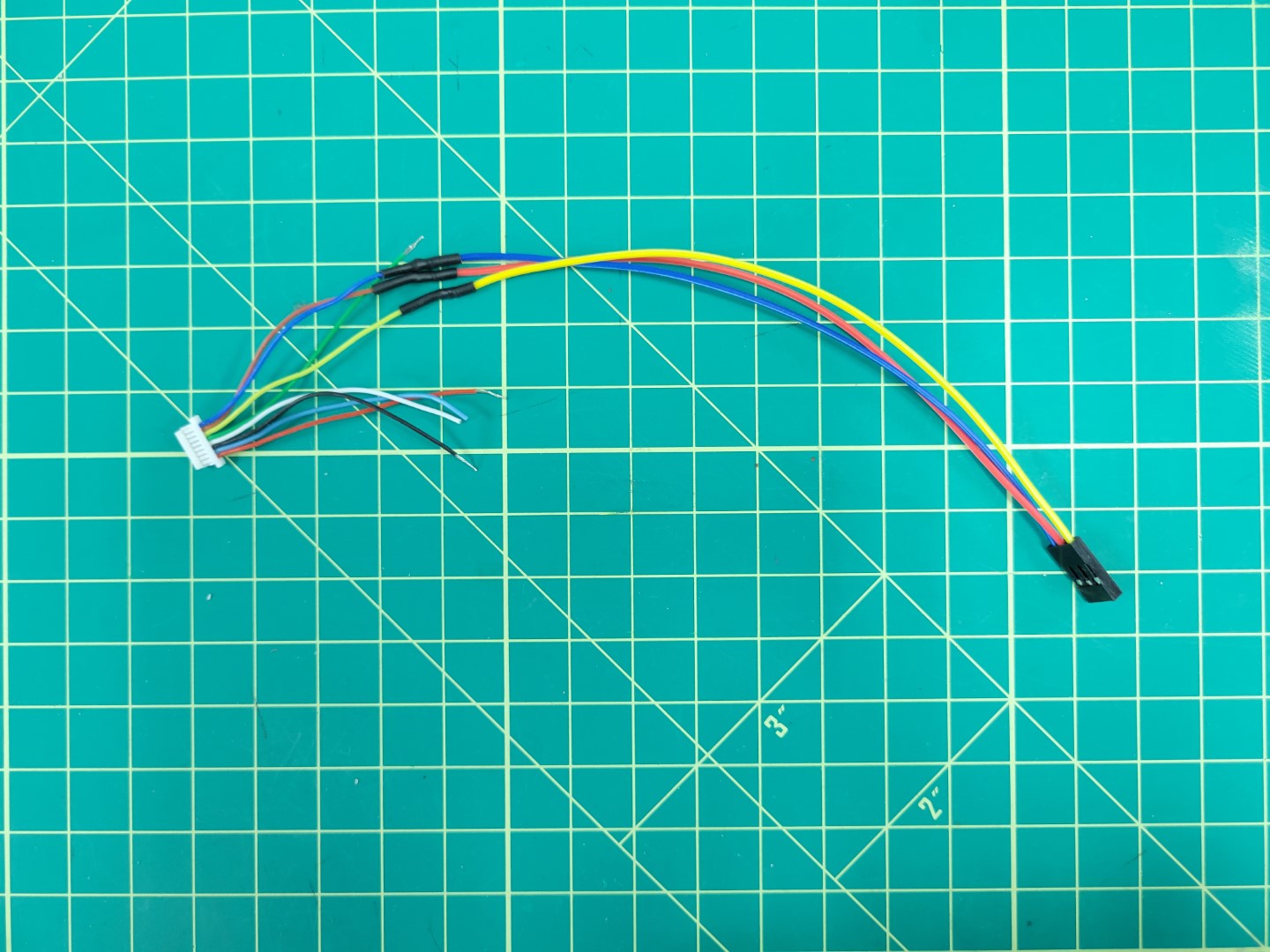
Repeat the soldering process for M1 (green), VBAT (red), and GND (black). Your new cable should look like the photo below.
Warning
One last reminder to make sure you clip the exposed leads from the TLM and CURRENT wires.
All wires soldered
Feel free to apply heat shrink over all your wires to keep things clean. If you don’t have heat shrink you can use electrical tape.
Plug your connectors into the Pixhawk PWM module as shown in the photo below.
The finished FC to ESC cable
In the bag of cables that came with your Pixhawk FC look for the 10 pin connector that attaches to the Pixhawk’s I/O PWM OUT port and the PWM IN port on the PWM module.
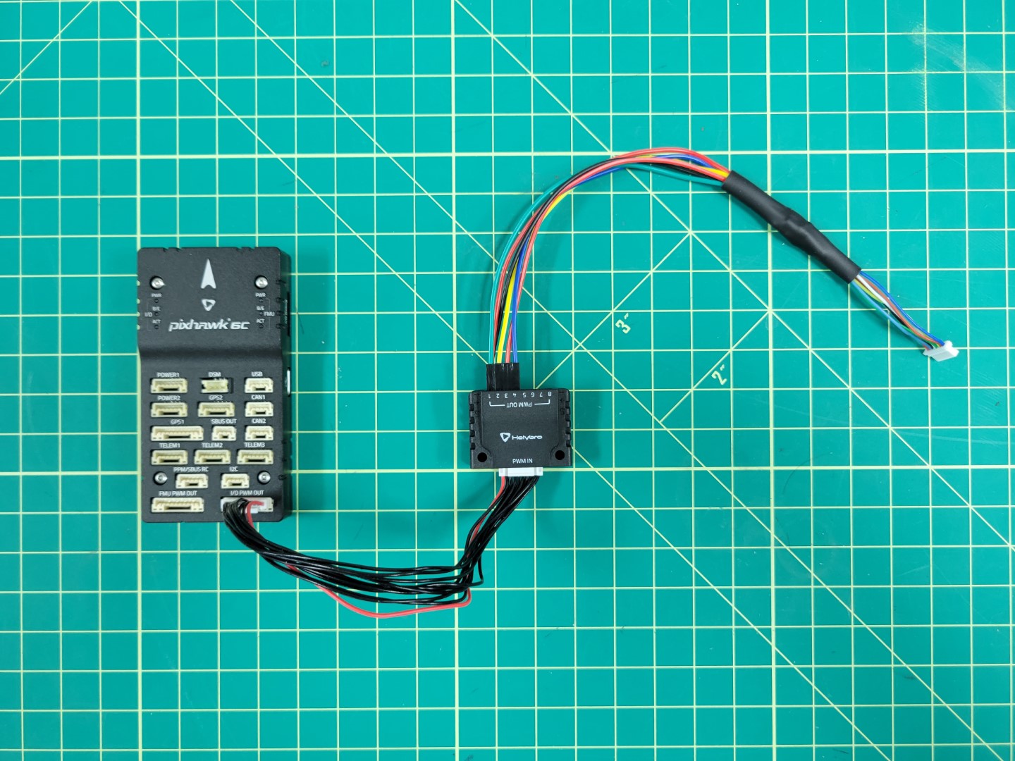
Connecting PWM module to Pixhawk
4.5 - FC Mounting
We will walk through mounting the FC and connecting the RX and power modules
FC Mounting
Locate the sheet of 3M double-sided adhesive pads and cut one out. Then cut it in half.
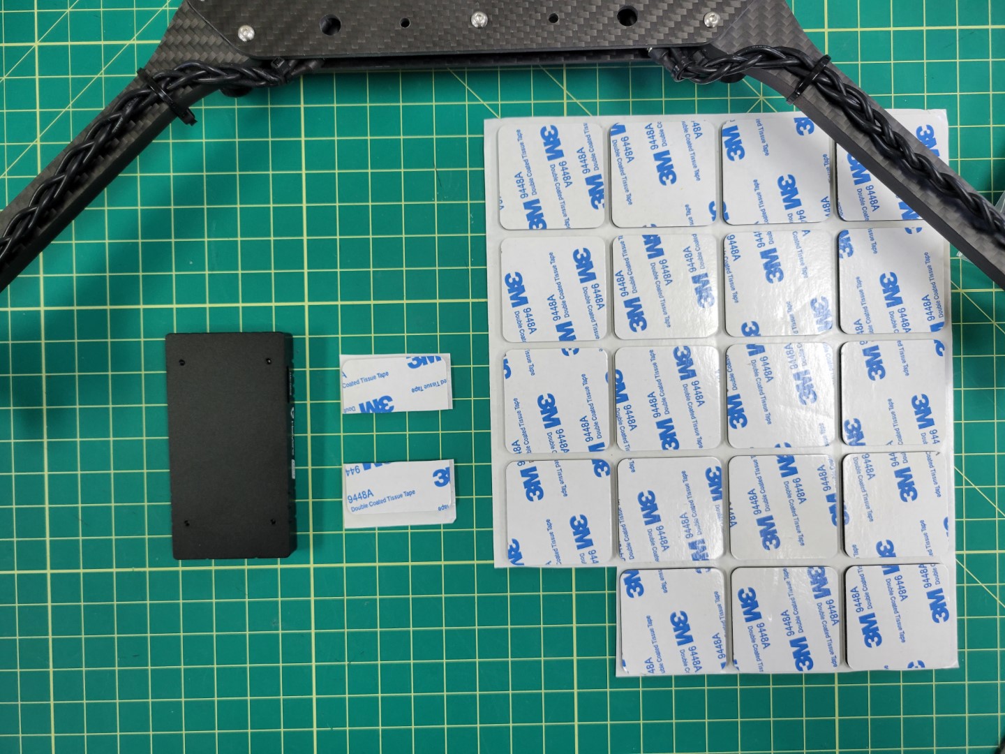
3M double-sided pads
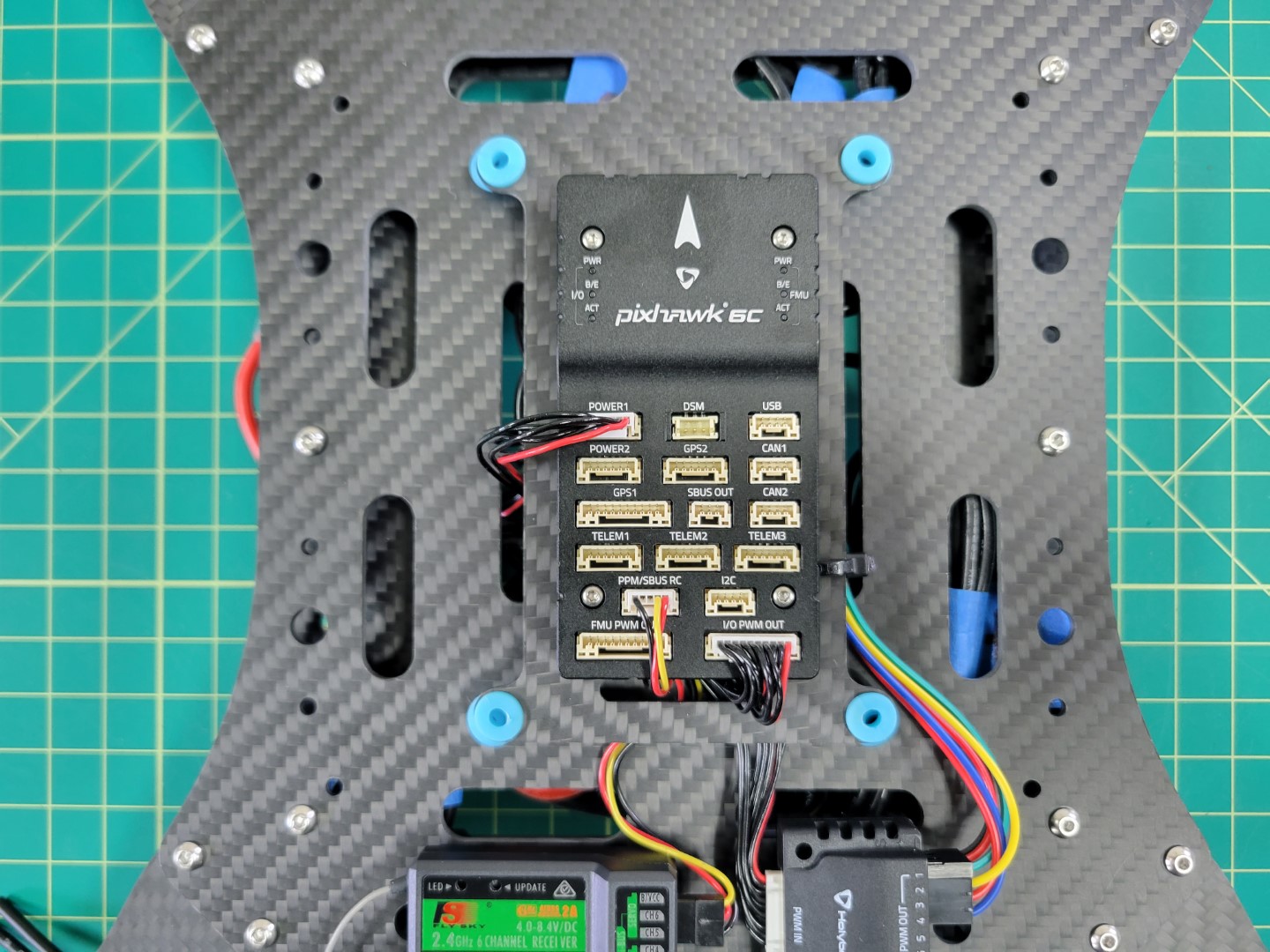
Place each half at the front and back of the Pixhawk FC.
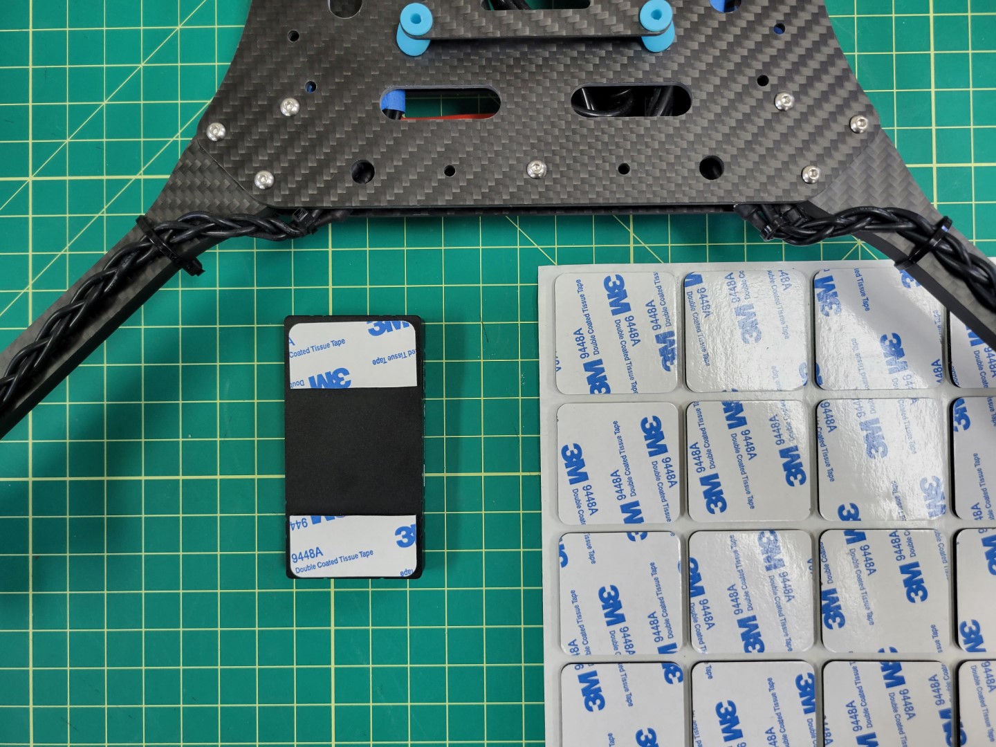
Pad applied to Pixhawk FC
Center the FC over the top tray and press it firmly into place.
Warning
Double check that the arrow on your FC is pointed forward towards motors M1 and M3.
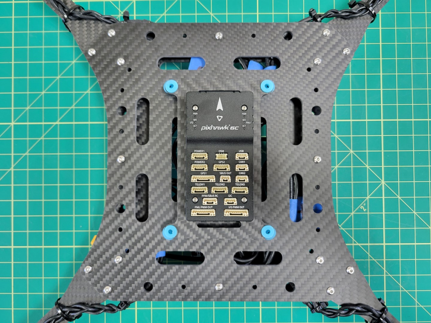
Pixhawk mounted to top tray
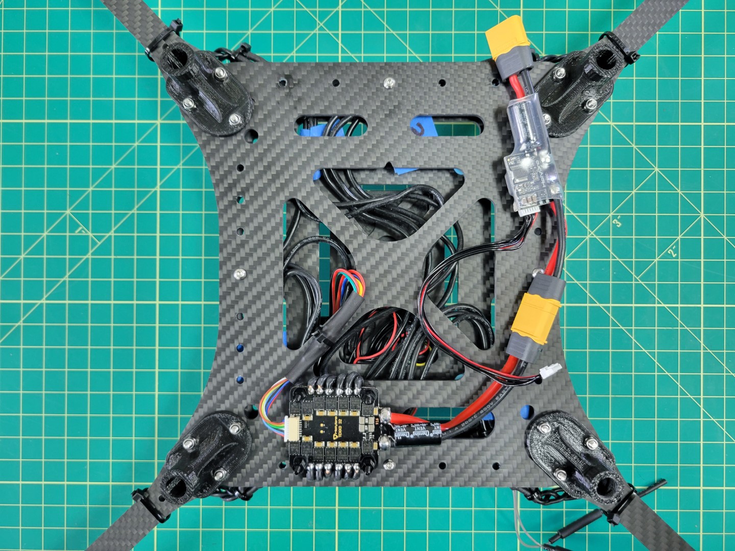
PWM Module Mounting
Let’s connect the cable we previously created to the ESC beneath the frame. You can see in the photo below that we’ve zip tied it to the mid bottom plate to keep it in place. Feed the other end of the cable to the top of the frame.
ESC/PWM cable secured to frame
Cut out a small piece of 3M tape and secure your PWM module to the frame as shown in the photo below. Wire up your connections.
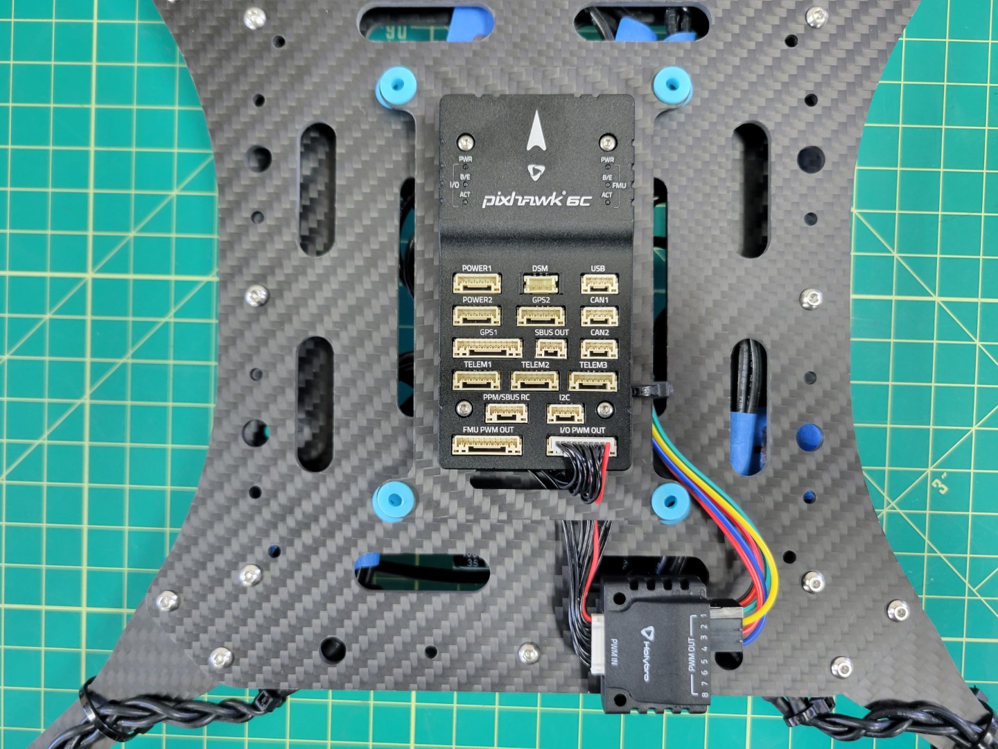
PWM Module mounted and wired
RX Mounting
The radio receiver (RX) will be mounted next. You can find the RX in the FlySky FS-i6S box. The cable to connect the RX will be in the bag of cables inside the Pixhawk box.
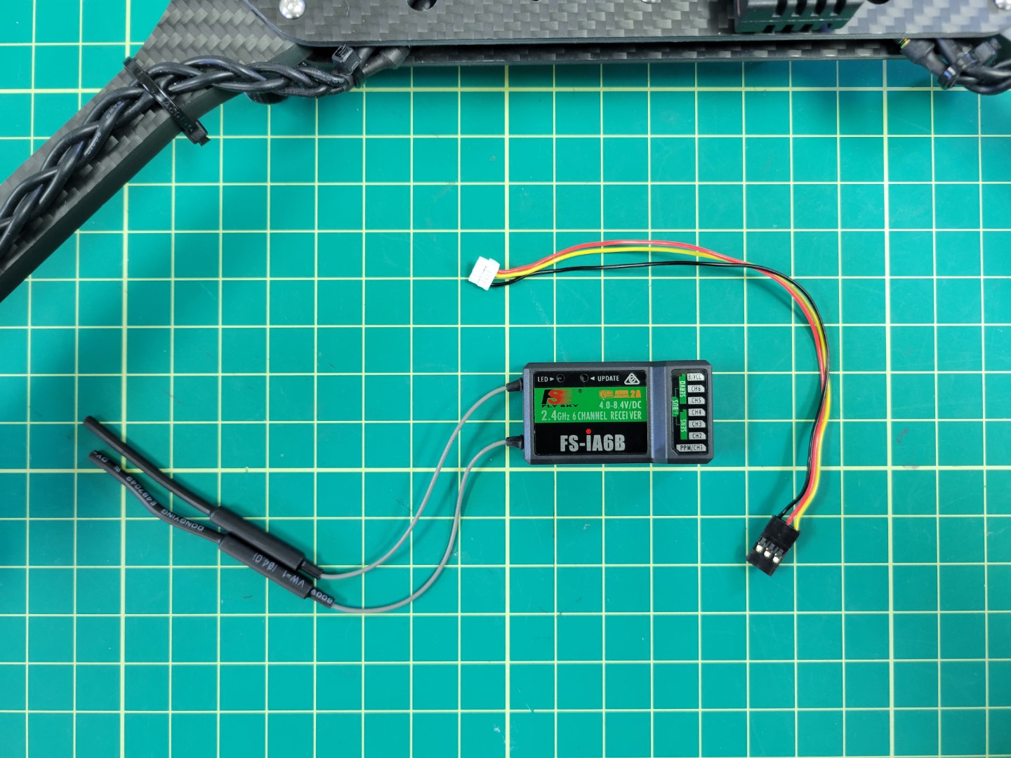
RX module and cable
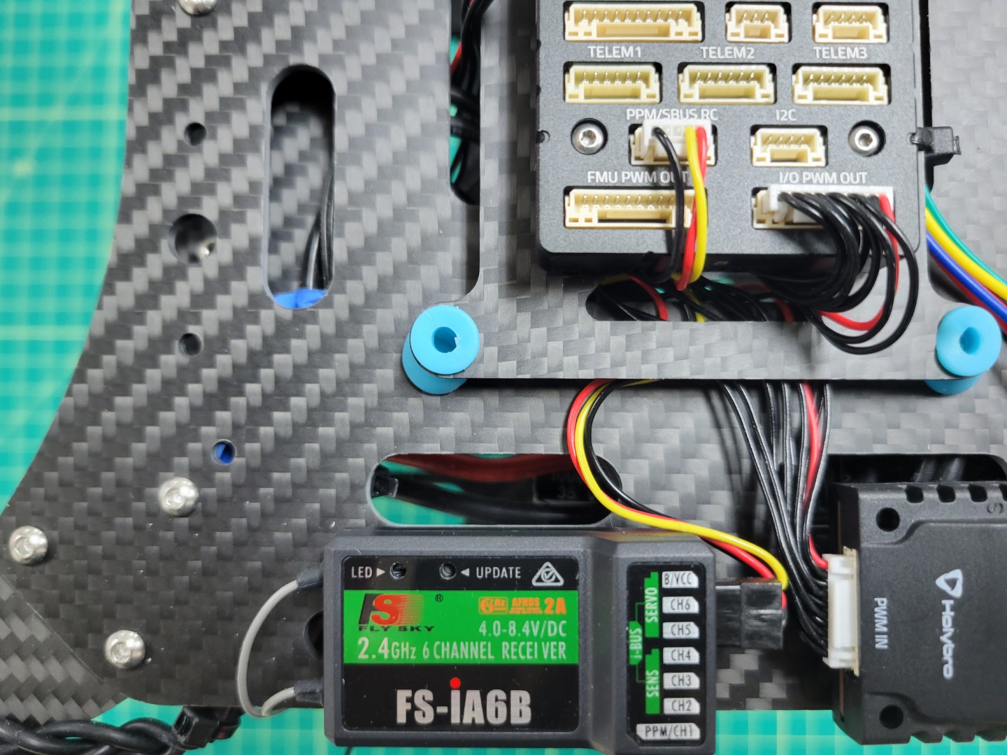
Mount the RX using 3M tape as shown below. Attach the cable to the PPM/SBUS RC port of the Pixhawk and the other end of the cable to the I-BUS SERVO port of the RX.
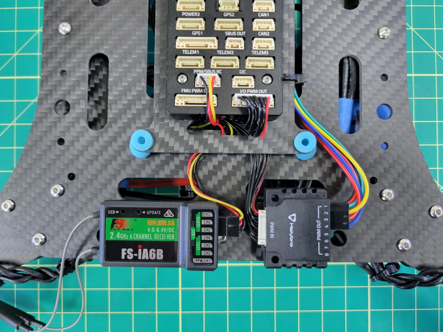
FS-iA6B RX Connected to Pixhawk
Power Module
The Pixhawk Power Module steps down the battery voltage for use by the FC. It also provides voltage and current monitoring. This monitoring will be critical for the AVR competition and will help teams understand the power profile of their drone. Both the power module and cable can be found in the Pixhawk box.
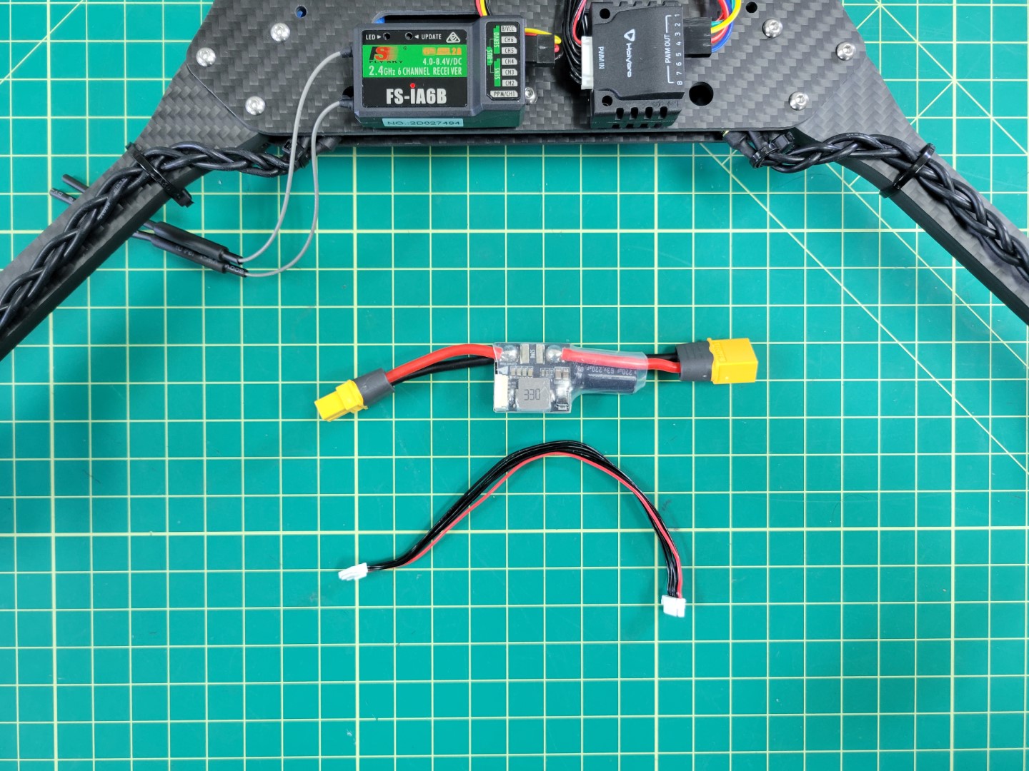
Pixhawk power module and cable
Plug the female XT60 connector of the power module into the male XT60 of the ESC. Then plug the FC cable into the port of the power module as shown in the photo below.
Connecting FC power module to ESC
Feed the power cable from the module to the top of the frame and plug it into the POWER1 port of the Pixhawk.
Pixhawk power connection
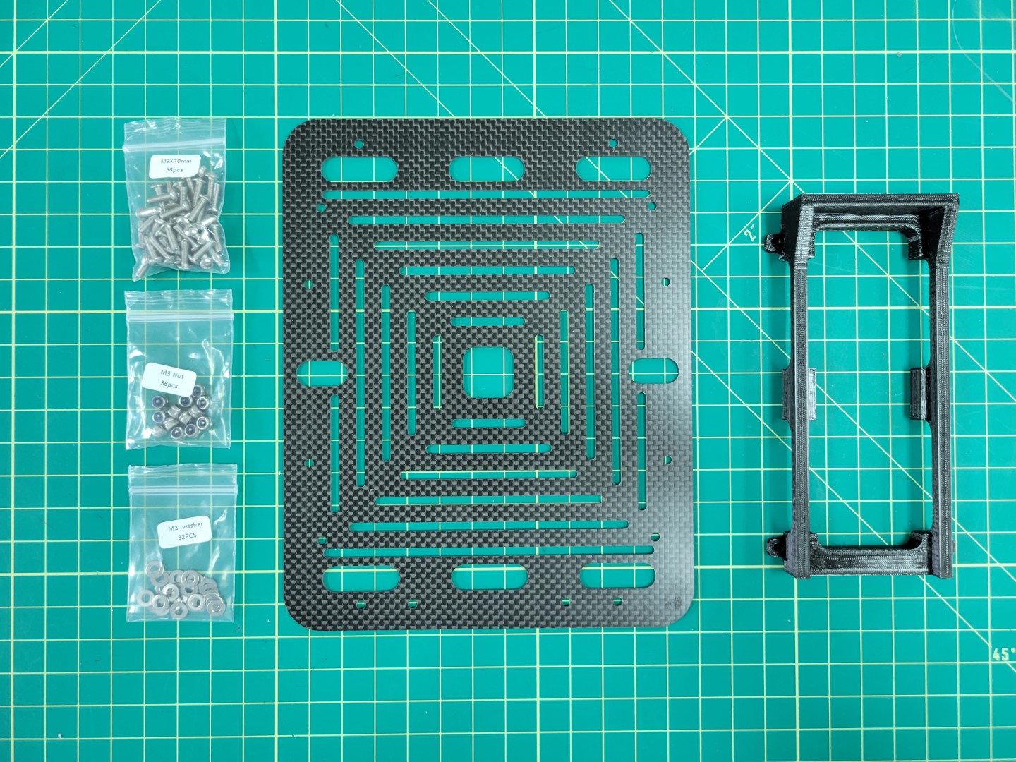
4.6 - Bottom Accessory Plate
This page walks through mounting the battery tray and attaching the accessory plate to the AVR frame
Battery Tray Assembly
Note
To proceed with this step you must 3D print the battery tray. An infill of 15% should be sufficient.
The parts necessary to mount the battery tray to the accessory plate are 10mm M3 screws, lock nuts, and washers.
Bottom accessory plate and battery tray
Insert the screws and washers from beneath the plate coming up through the battery tray. Secure each corner with a lock nut as shown in the photo below.
Battery try mounted to accessory plate
Attaching Accessory Plate
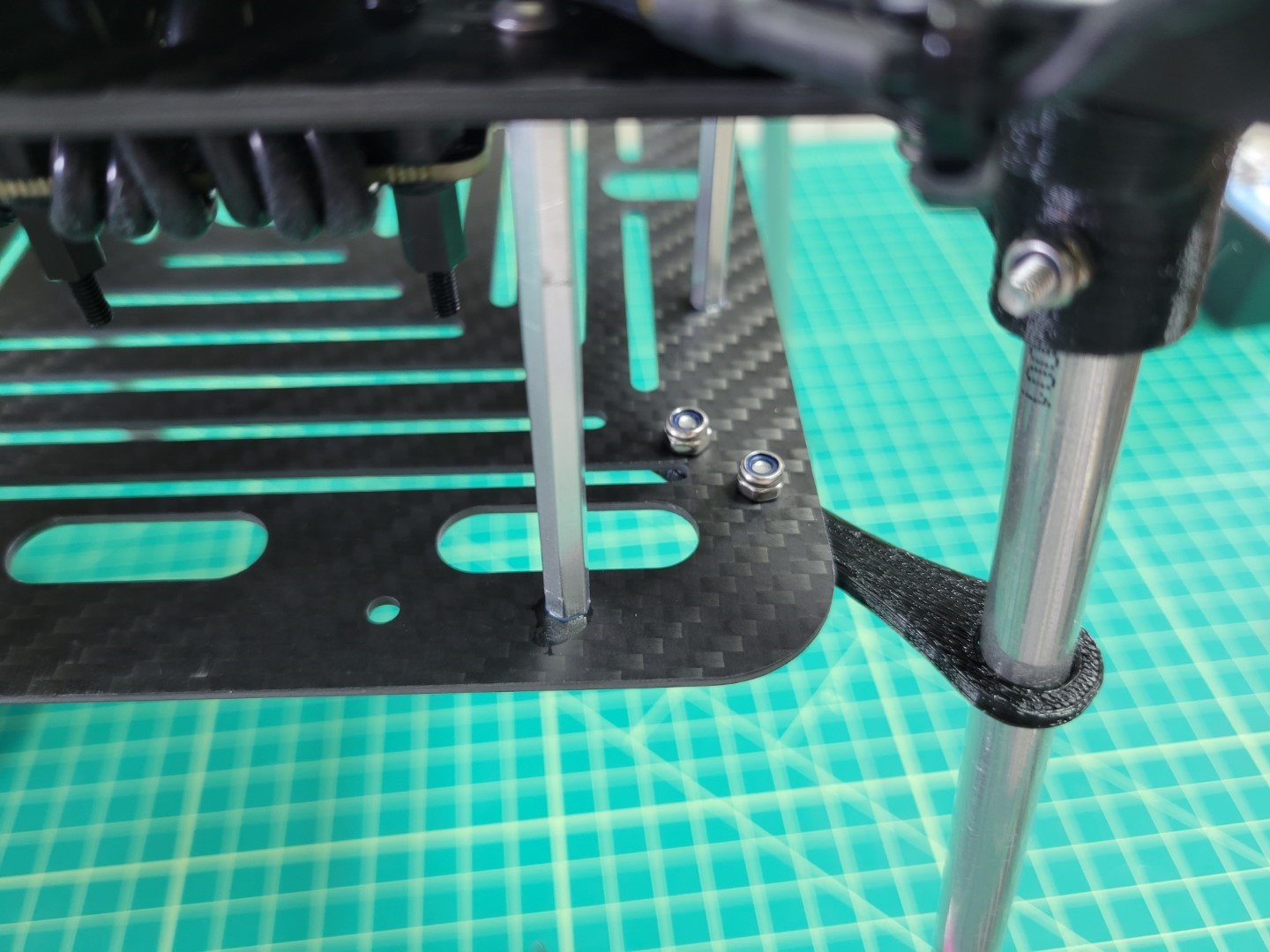
Let’s attach the bottom accessory plate to the mid plate assembly of the AVR frame. You will need the 60mm standoffs and 10mm M3 screws that come with your kit.
Standoffs and screws for accessory plate mounting
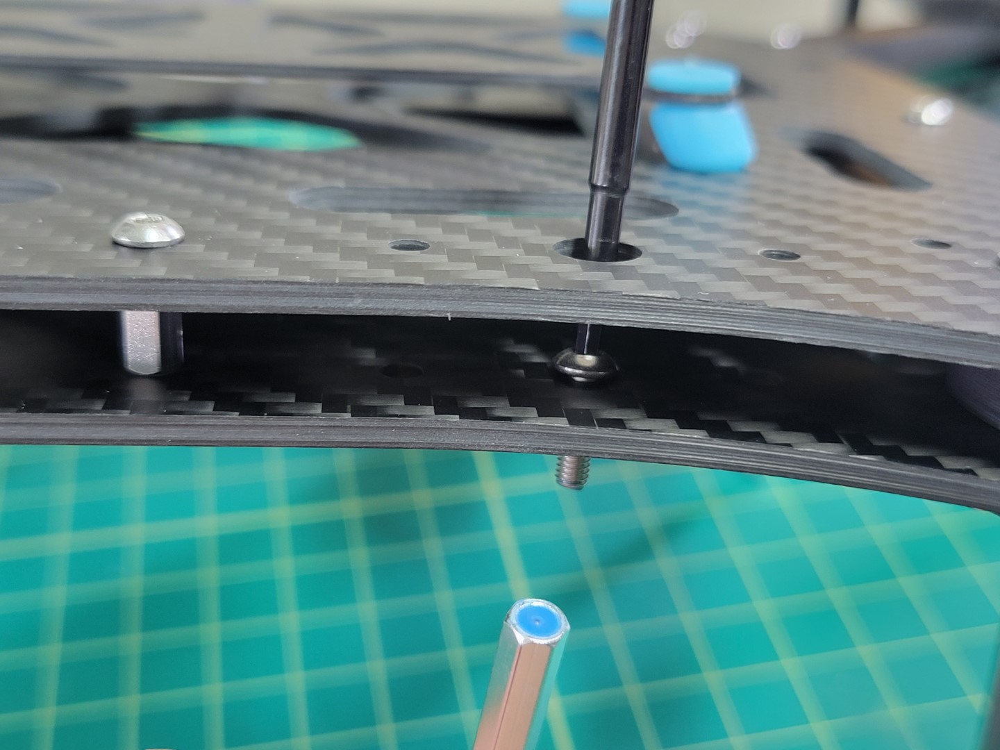
From the top of the midplate assembly locate the eight larger access holes. Place a 10mm screw through each access hole into the mid bottom plate. A pair of needle nose pliers are very helpful for this step.
Access hole for 10mm screw
Place a small drop of Loctite into the standoff and screw into place using a 2.0mm hex driver.
Loctite applied to 60mm standoff
Repeat this process for all eight standoffs. Flip your AVR frame over so that the standoffs are facing up. Place a drop of loctite into each of them.

Standoffs with Loctitue
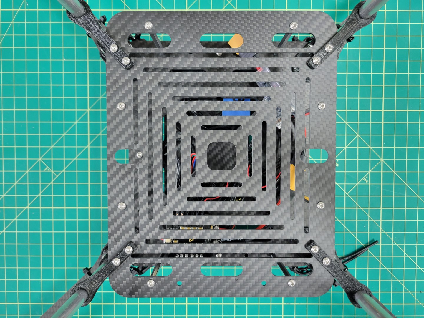
Place the bottom accessory plate onto the standoffs and secure with 10mm screws.
Warning
Make sure that the two holes denoted by the yellow circles below face the front of the drone. These holes will be essential when mounting the ZED Mini camera during advanced drone assembly.
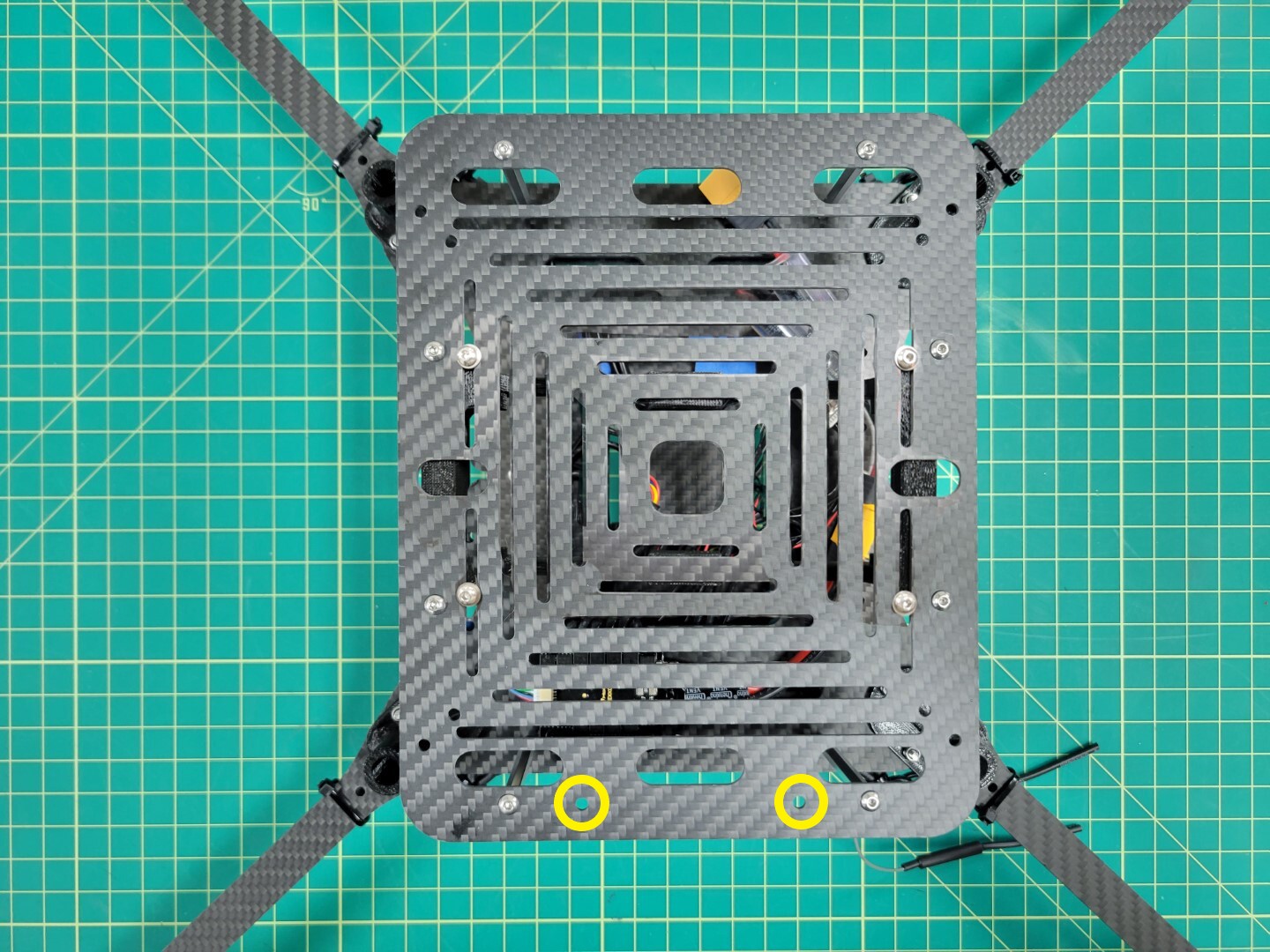
Bottom accessory plate secured and ZED Mini holes facing front of frame
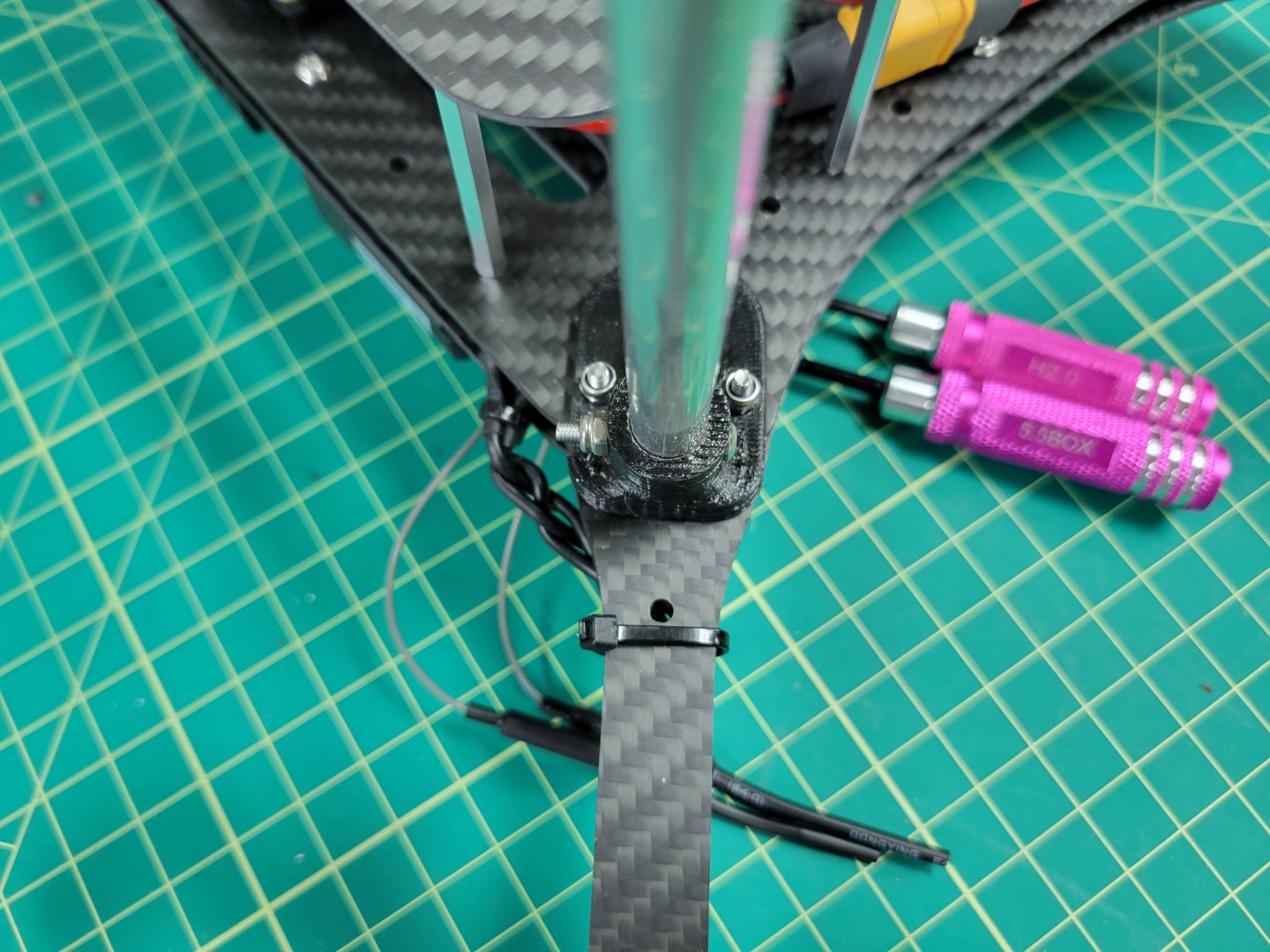
4.7 - Landing Gear
This page will guide you through the process of drilling and installing your landing gear
Landing Gear Drilling and Mounting
Note
To proceed with this step you must have 3D printed the landing gear brace and foot (x4).
Your AVR kit ships with 4 x 9" aluminum rods that are used for landing gear. As you get further into the advanced part of the build you can shorten these rods with a metal hacksaw. Customization is largely dependent on what accessories you have mounted to your drone.
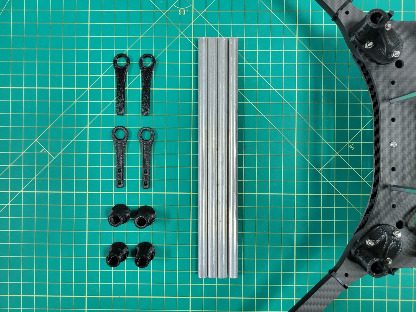
3D printed parts and aluminum rods for landing gear
Attaching the aluminmum rods to the landing gear mounts will require drilling holes in each rod. We will walk through this process in detail to ensure success and minimize frustration. You will need a drill, 1/16" bit, 1/8" bit, screw (or nail), and a Sharpie.
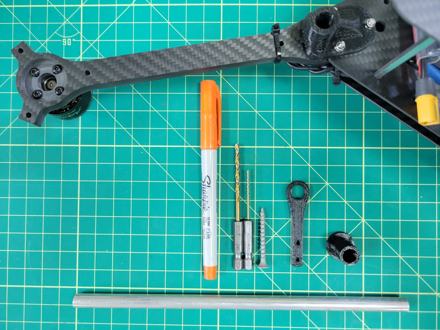
Tools necessary for drilling aluminum rod
The first thing you will need to do is place an aluminum rod into the landing gear mount as shown below. In most cases this will be a tight fit so we recommend using a bit of force and rotating the rod clockwise and counterclockwise. This will cause some of the plastic from inside the mount to wear away.
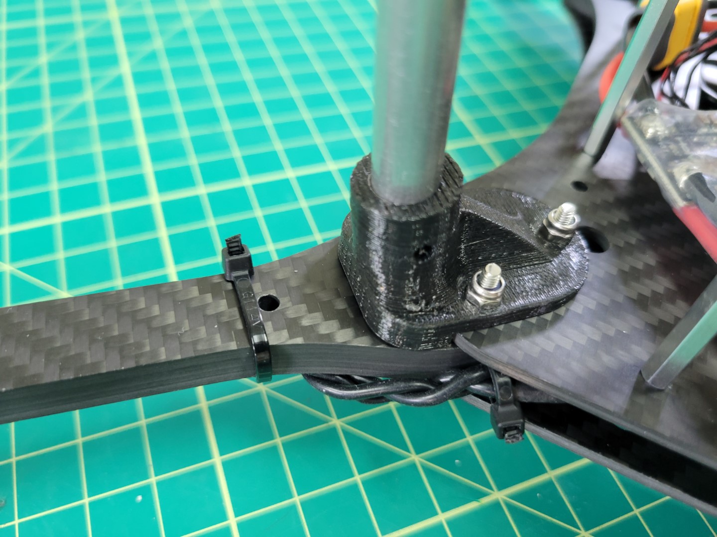
Placing the aluminum rod into the mount
In the photo below you can see some of the plastic shaved off inside the mount.
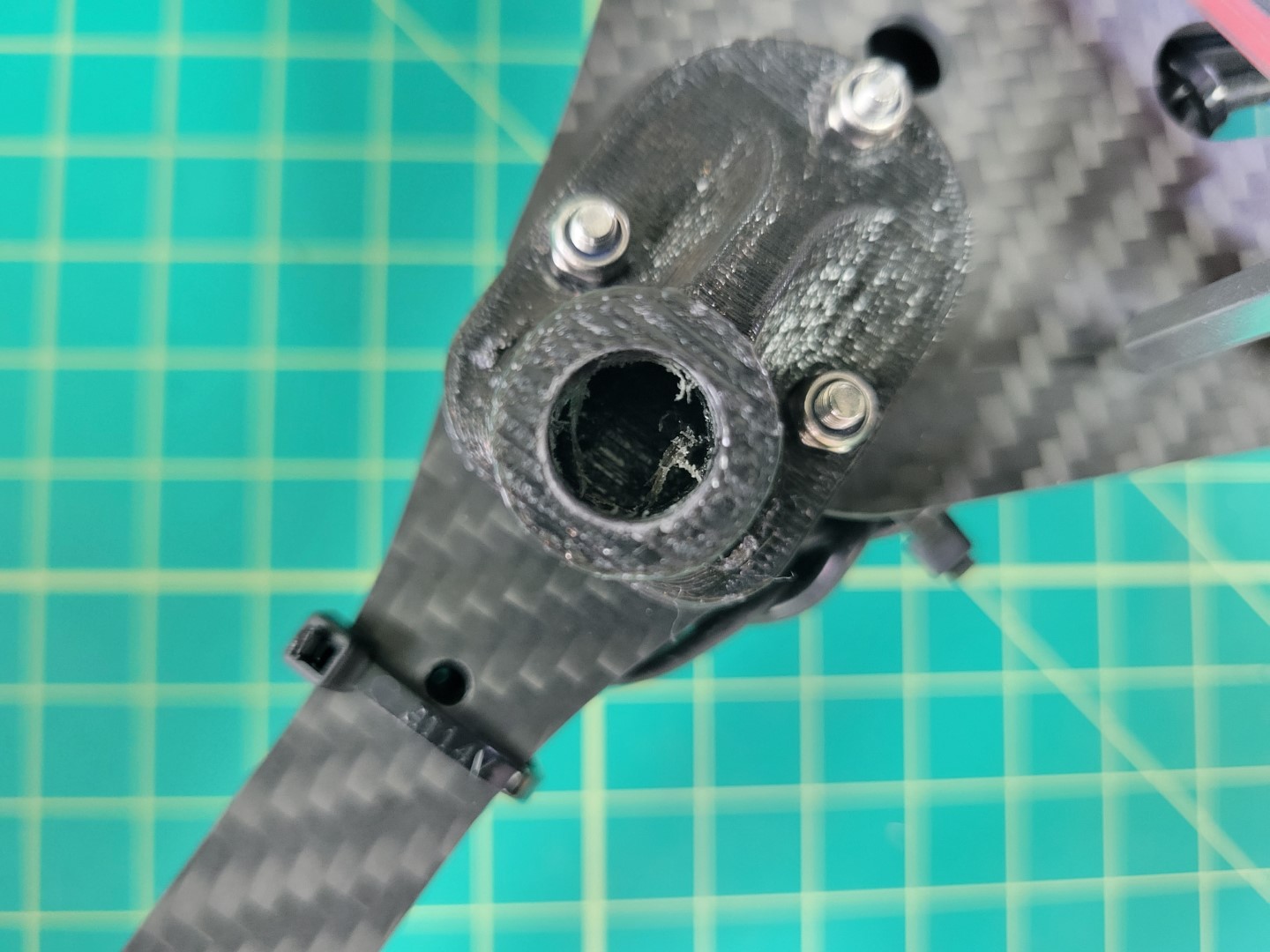
Repeat this process until the rod is flush with the bottom of the mount.
Warning
Use caution as you rotate the rod into the mount. Only use a force perpendicular to the mount. You don’t want to run the risk of cracking the mount and having to print and install a new one.
Tip
If you find this process cumbersome you can try to use a 3/8" drill bit to hollow out the mount. Once again, use caution to prevent the mount from cracking.
Landing gear mount with rod inserted
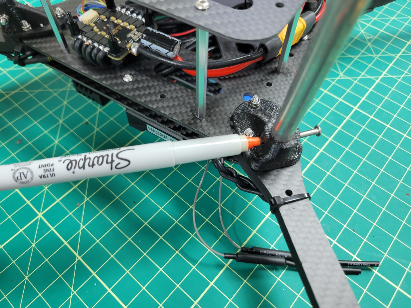
Use a Sharpie to mark a hole on one side of the rod. Do not mark both sides. There is little margin for error so we will drill one side and repeat this process for the other.
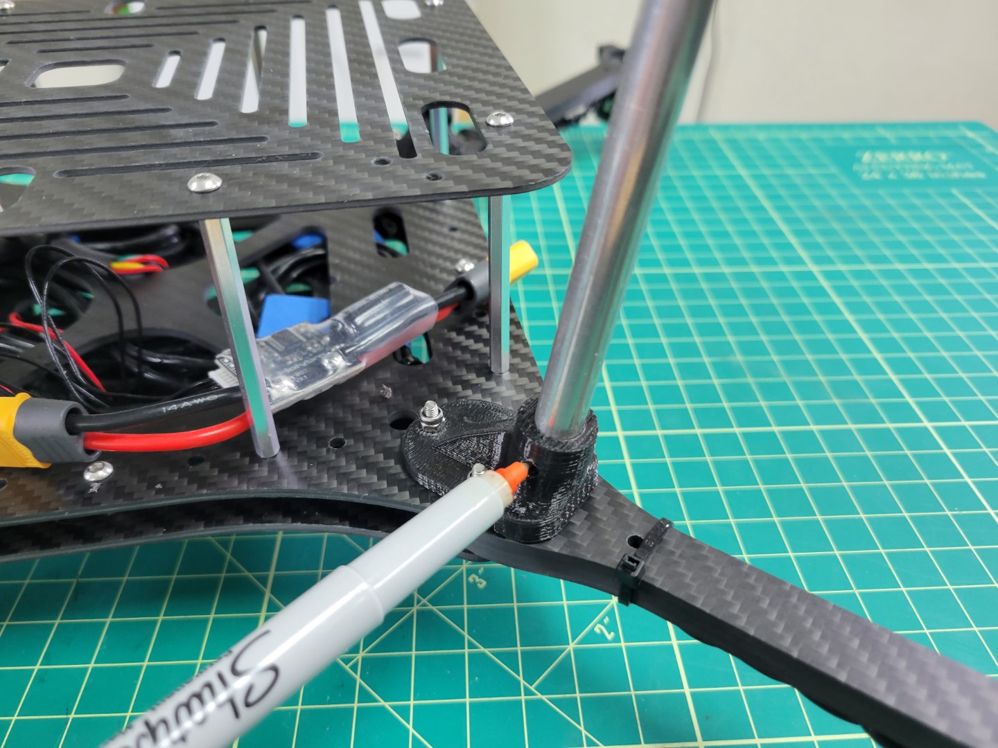
Marking a hole for drilling
It can be challenging to accurately drill a hole in the aluminum rod. Clamp the rod to a piece of wood and then place a screw or nail in the center of the Sharpie mark. Tap the screw several times with a hammer to create an indentation in the metal.
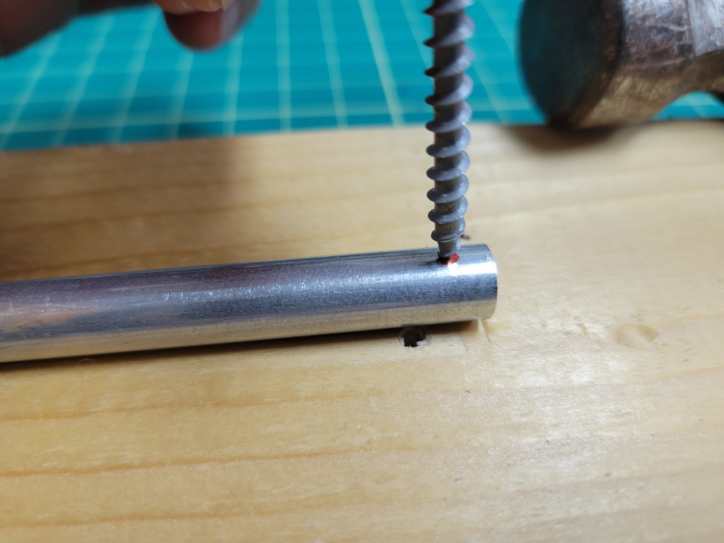
Tapping the screw into the rod
Use the 1/16" bit to drill a starter hole. The indentation you created will keep the bit from slipping around. This drill bit is very fragile so don’t use too much force.
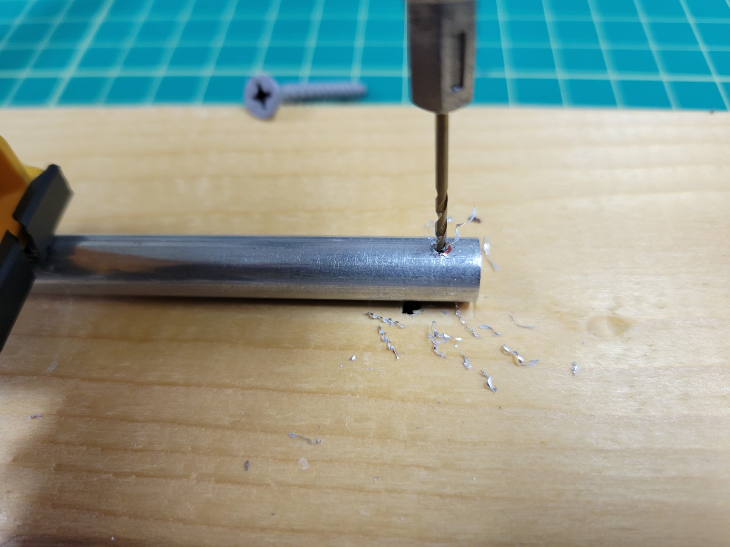
Drilling 1/16" hole in rod
Now use the 1/8" drill bit to enlarge the hole. This will be the final size necessary for our M3 22mm screws.
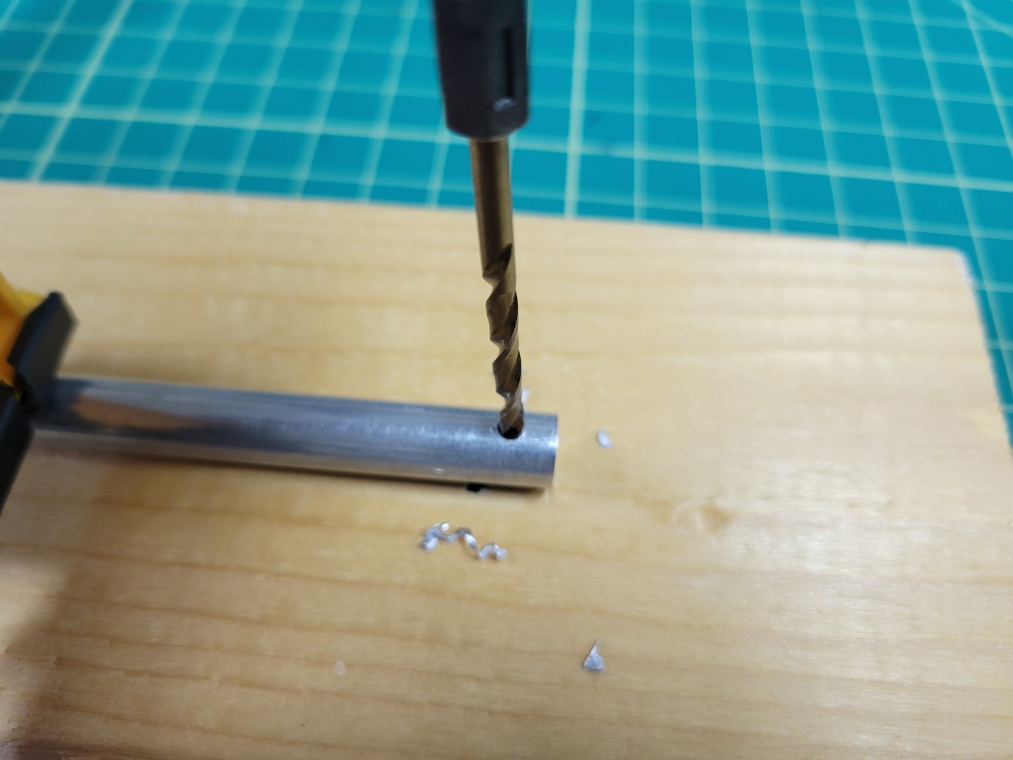
Drilling 1/8" hole in rod
Place the rod back into the mount make sure it’s all the way in. Slide a 22mm screw through the mount and into the hole you just drilled. Make sure everything fits well and then mark the other side with your Sharpie.
Marking other side of rod for drilling
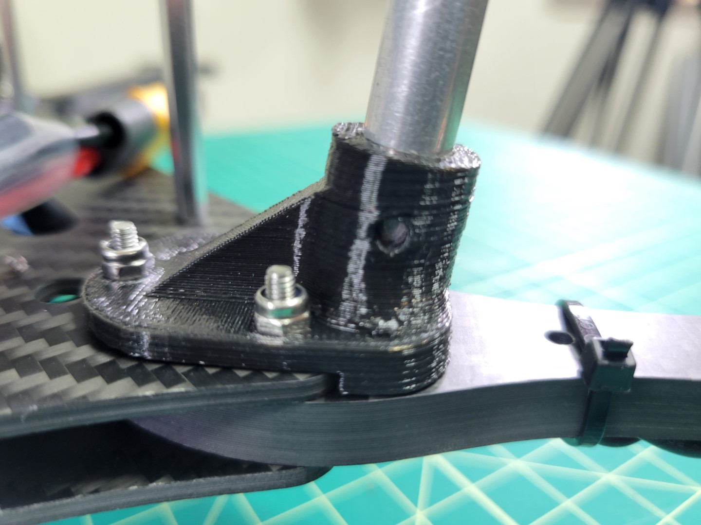
Repeat the tapping and driling process for the other side of the rod. Once that’s complete place the rod back into the mount, slide the 22mm screw all the way through, and secure the rod with a lock nut.
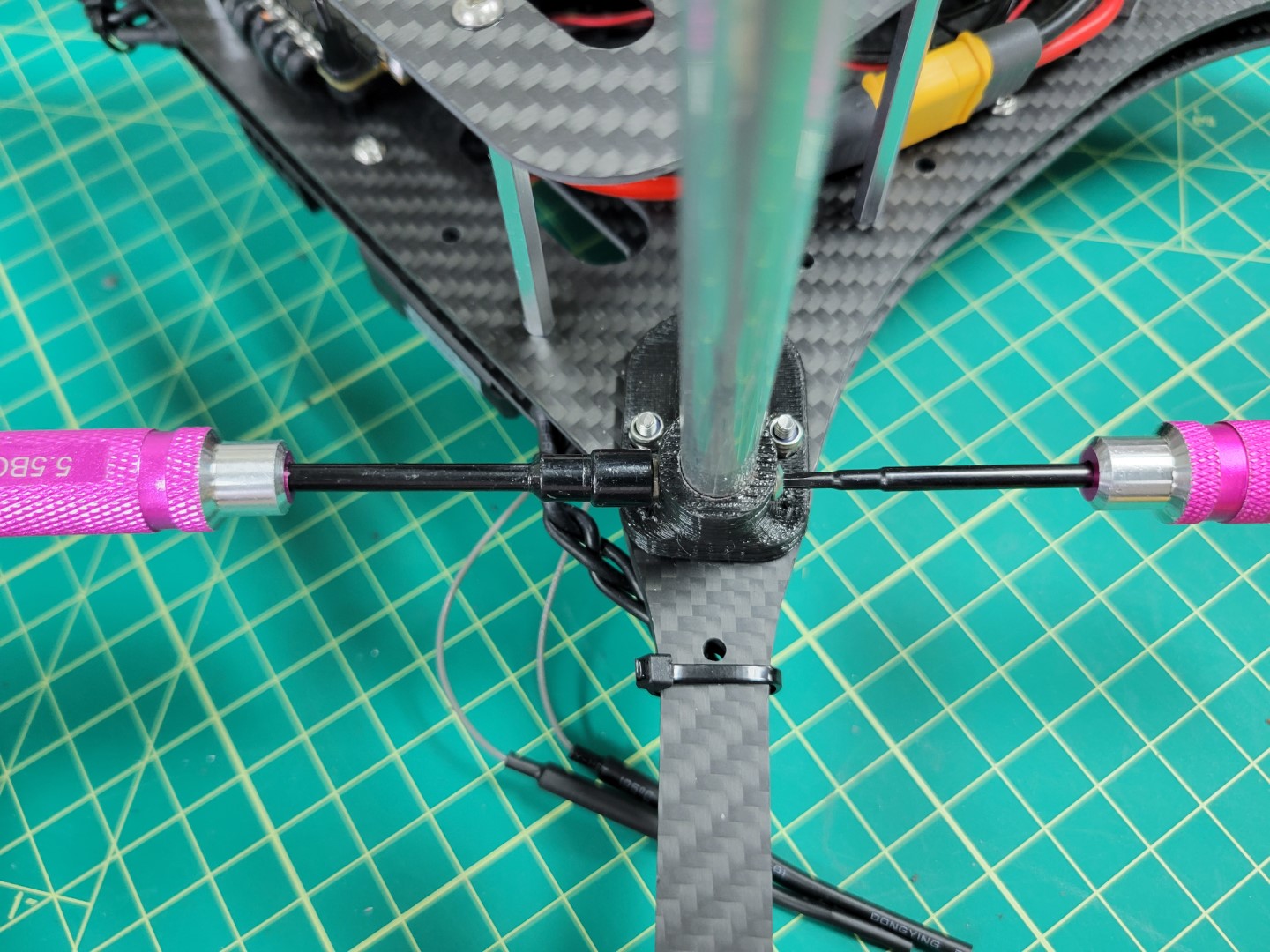
Screwing landing gear into the mount
Once all four rods are mounted we will proceed to attaching the landing gear braces which provide extra support.
Landing gear securely mounted
Landing Gear Brace Mounting
The landing brace provides additional support by securing the rod to the bottom accessory plate. Use two 8mm screws and lock nuts as shown in the photos below. Repeat this process for all four legs.
8mm screws through landing brace and accessory plate
Lock nuts securing landing brace
Landing brace installation complete
There’s a good chance that the feet of the landing gear will require press fitting onto the rod. You can use a 3/8" drill bit to shave some of the plastic from the foot.
Note
The foot has a slight angle to it. Be sure to rotate it so the bottom of the foot is flush with the floor.
If the foot is loose feel free to use a drop of hot glue to hold it in place.
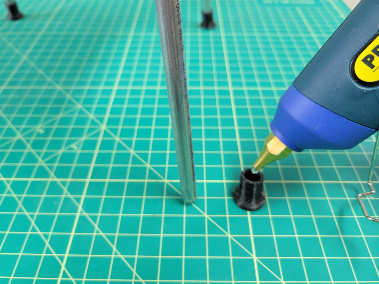
Applying hot glue to landing gear foot
Repeat the process for all four feet.
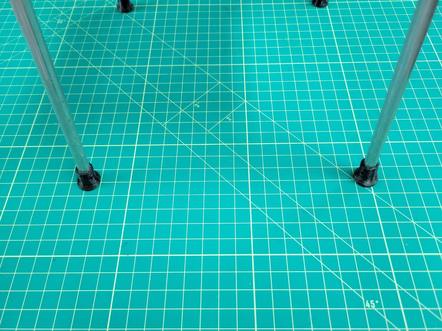
Landing gear feet installed
Congrats!
You have completed the first part of the build process! Let’s move to the next section to gain a solid understanding of battery management.
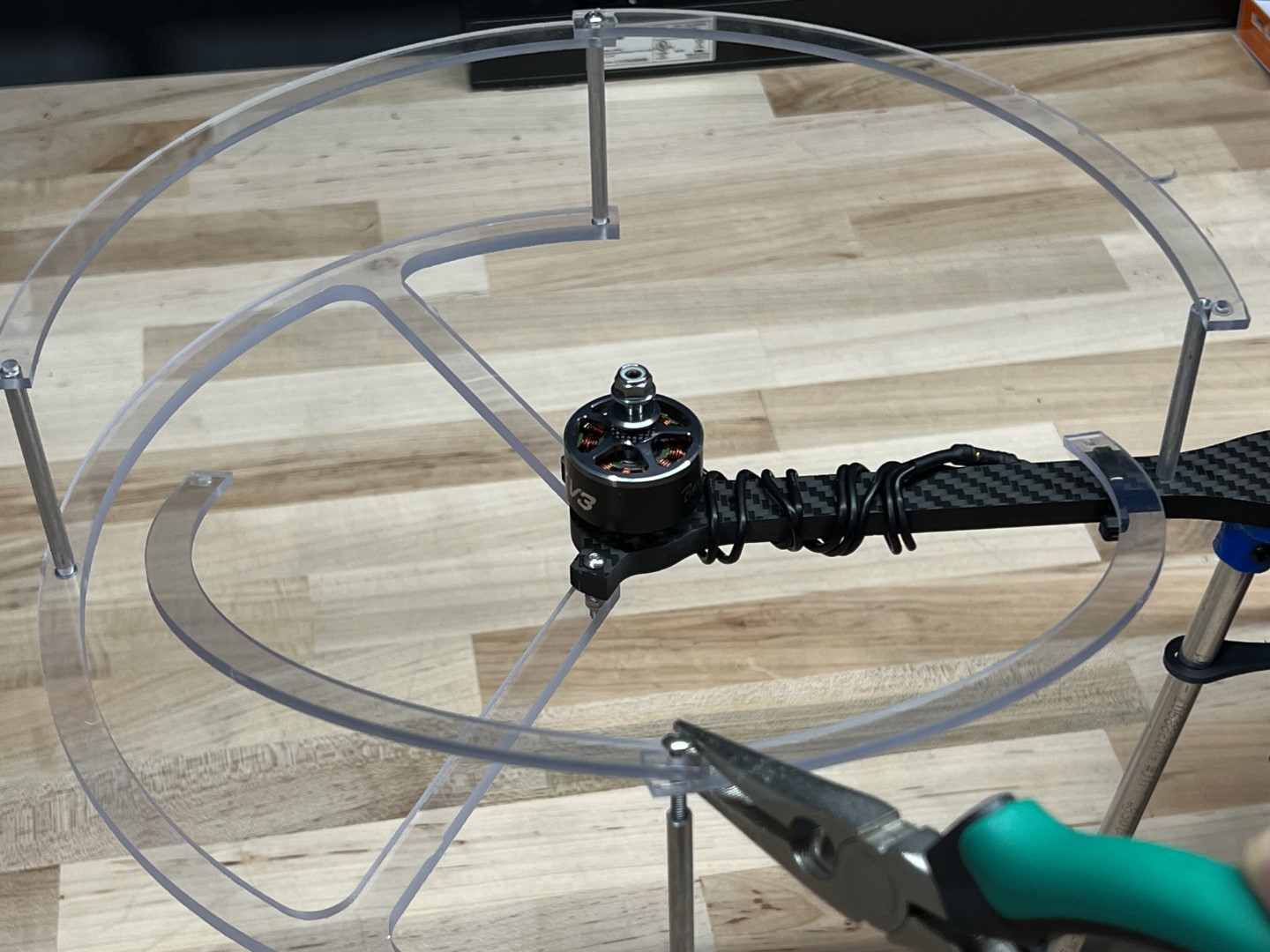
4.8 - Prop Guard Assembly
The prop guards will protect your drone should it inadvertently come into contact with the net.
There are not enough M3 x 22mm bolts included in your kit to assemble the prop guards.
Please refer to notice a bottom of page for solution options.
These instructions use the recommended solution option.
Prop Guard Mounting
This section will guide you through the assembly of the propeller guards.
Warning
Do not attempt to drill or machine carbon fiber motor arms.
Machining will create carbon dust which can cause irritation to skin, eyes, or lungs from fine resin dust particles.
Proper ventilation and respiratory equipment are required to machine carbon fiber components.
Locate the following items below in both your first and second kit shipments.
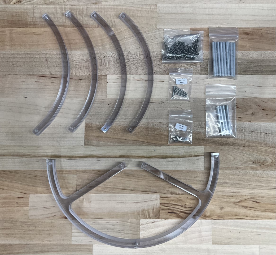
Prop Guard Components and Hardware
Fasten lower prop guard bracket to motor arm using agreed upon method.
Warning
Do not allow wet Loctite to come in contact with the polycarbonate prop guards.
Loctite is caustic to polycarbonate and can cause the prop guards to crack and ultimately fail.
Lower Bracket Fastened to Motor Arm
Fasten a short stand-off to the motor arm hole closest to the drone body arm using the M3 x 15mm bolt.
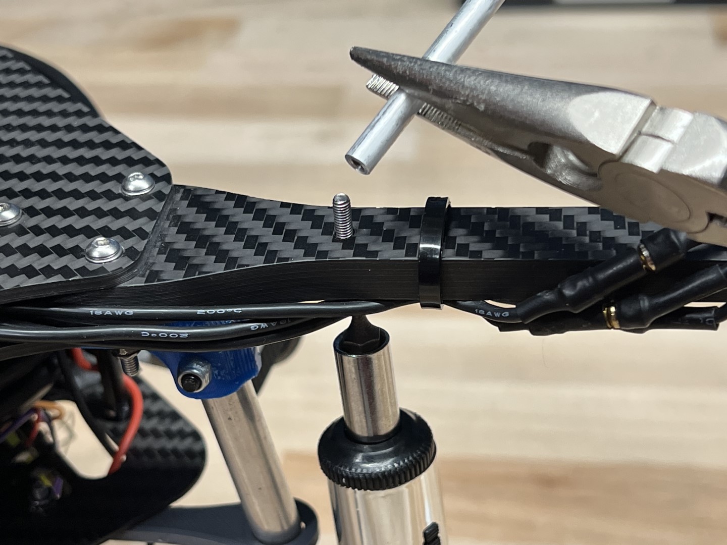
Securing Short Stand-off
Fasten the long stand-offs to the 3 mounting locations on the lower prop guard bracket using the M3 x 15mm bolts.
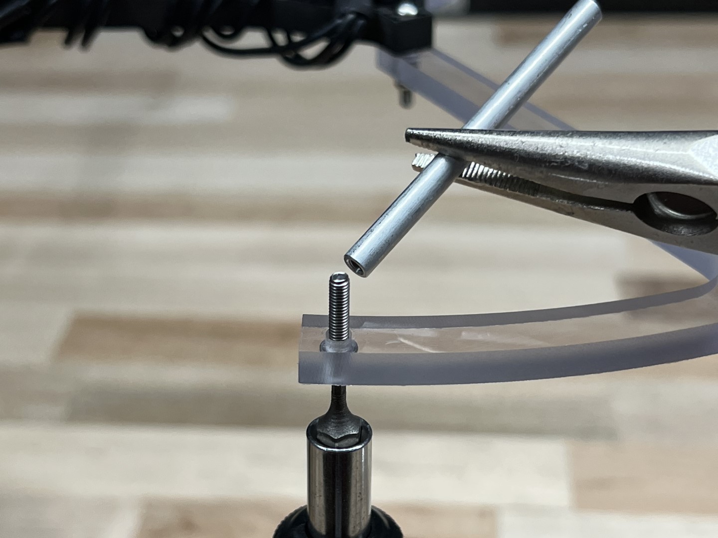
Securing Long Stand-offs to Lower Bracket
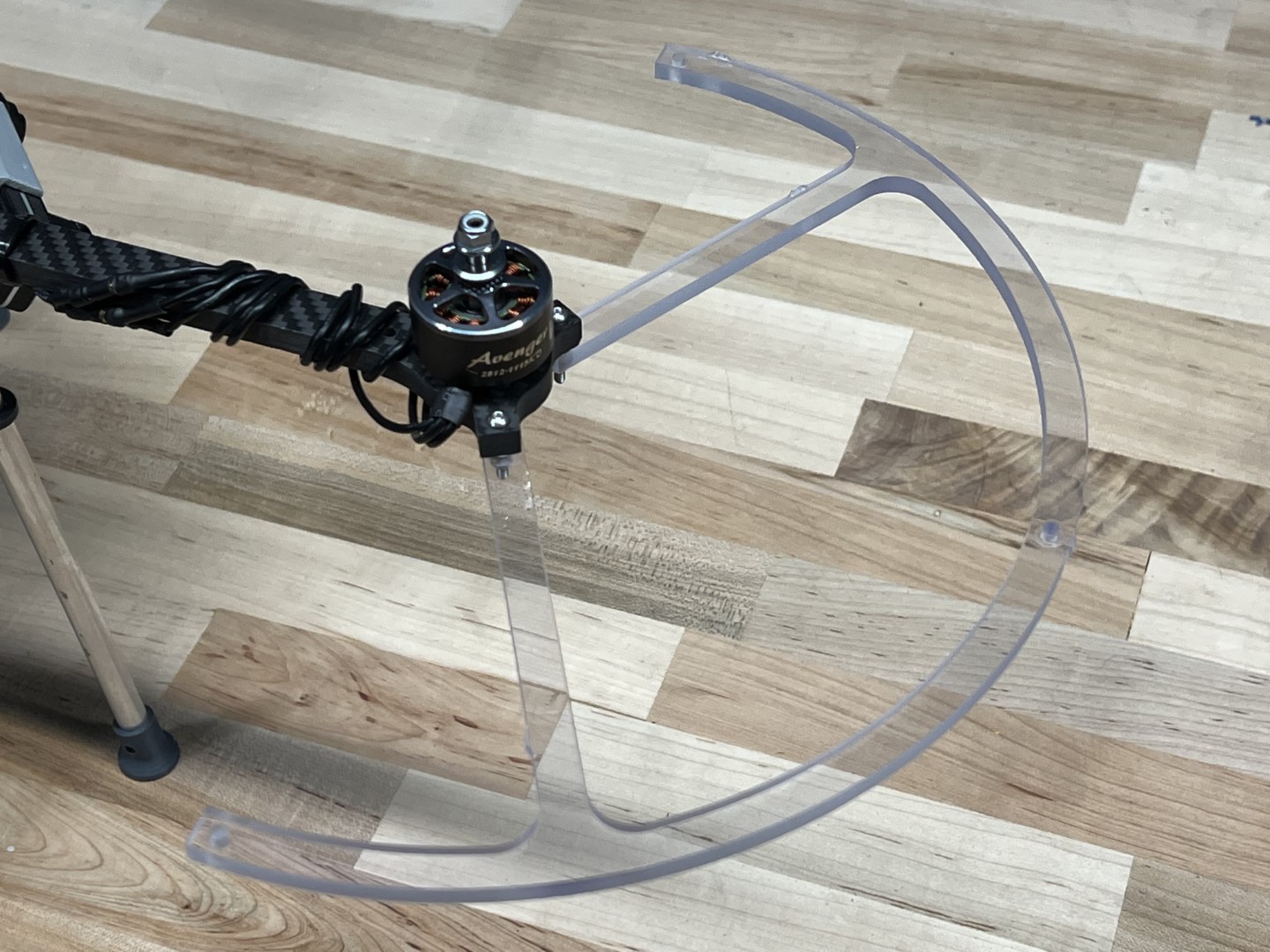
The assembly should match the following photo with the bottom prop guard and all stand-offs mounted.
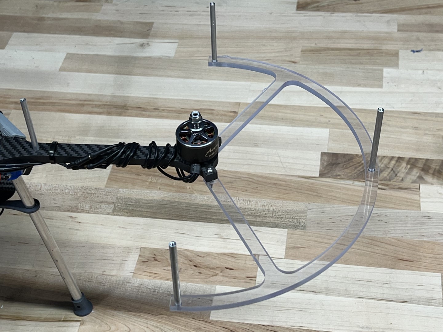
Stand-offs and lower bracket installed
Stack two upper prop guard brackets on top of one another, place a M3 x 15mm bolt through the two holes, and fasten to one of the 4 stand-offs as shown in picture below.
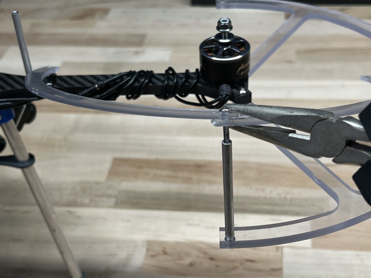
Securing 1st Set of Upper Brackets
Stack the remaining 2 upper brackets such that the upper bracket sits on the lower bracket of the previous step; likewise, the current lower bracket should sit below the upper bracket from the previous step.
Secure the brackets to the stand-off using a M3 x 15mm.
Securing 2nd Set of Upper Brackets
Check that the top brackets are stacked in the correct order and secure to the remaining 2 stand-offs with 2 M3 x 15mm bolts.
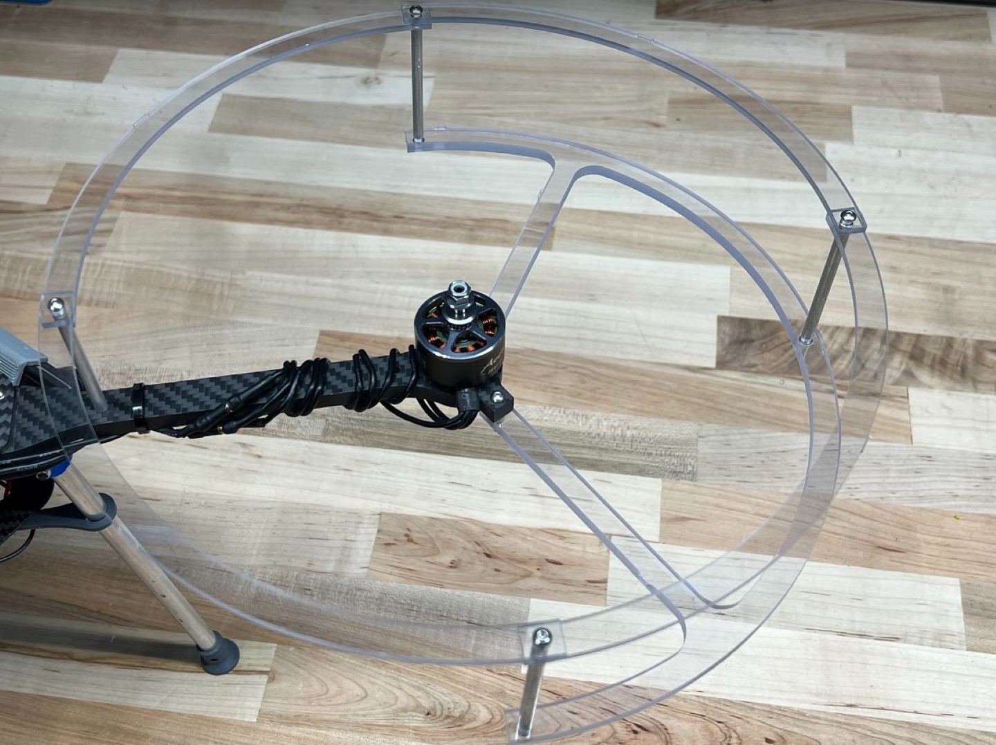
Assembled Prop Guard
Repeat on the remaining three motor arms.
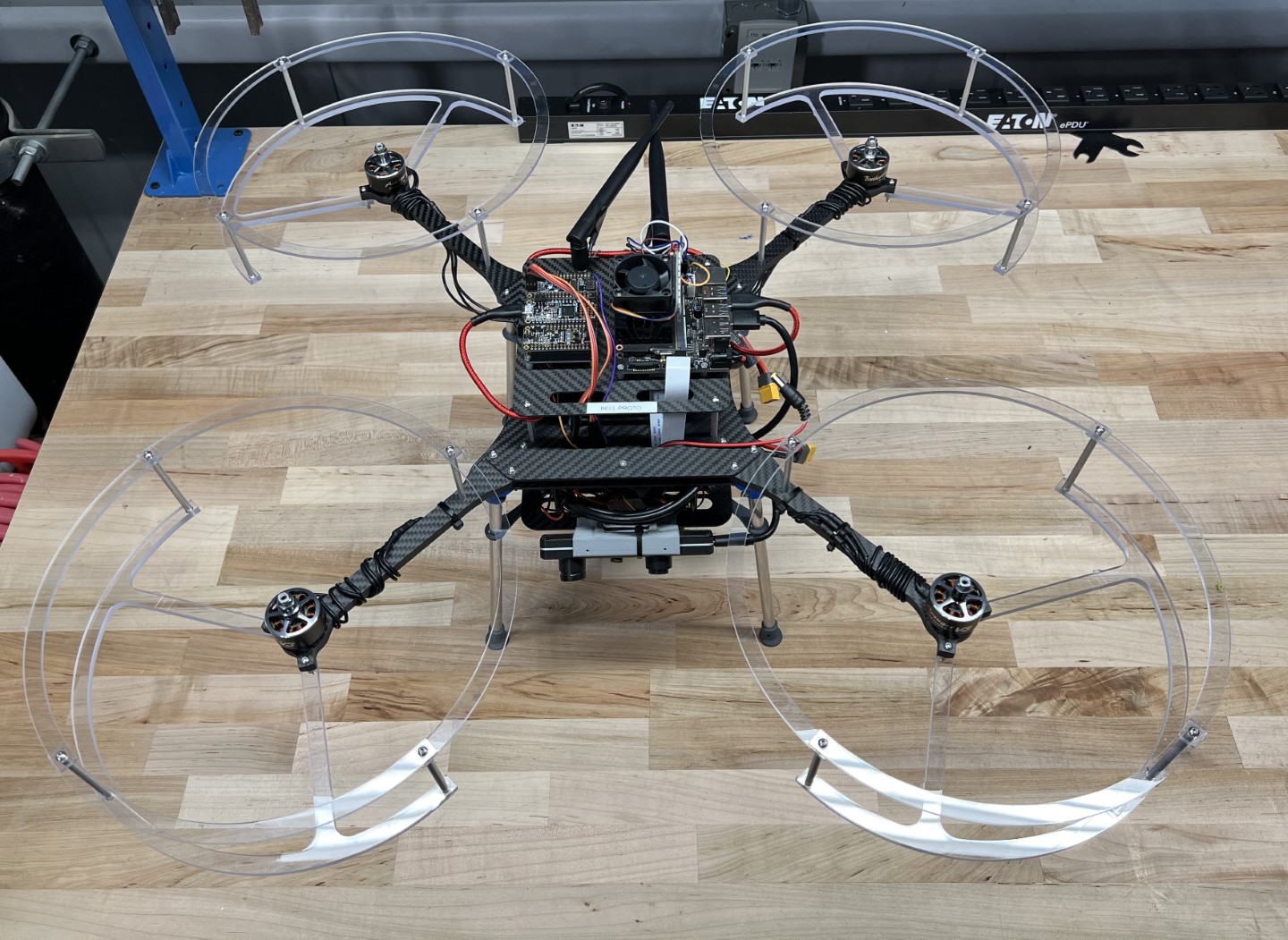
Completed Drone with Prop Guards
Congrats, you have now properly assembled the prop guards to your AVR drone!
Note
There are not enough
M3 x 22mm bolts included in your kit to assemble the prop guards.
Teams may choose from the list of solutions below, but are also encouraged to think of alternative solutions that are not listed.
- Purchase the remaining M3 x 22mm bolts (Recommended solution)
- Pros: Quick fix, doesn’t require any modifications to drone parts
- Cons: Spend money and coordinate travel to store or buy online
- Repurpose the M3 x 22mm bolts currently used on the upper landing gear mounts for mounting the prop guards.
The M3 x 20mm Nylon bolts included in your kit will act as a substitute for the Aluminum bolts on the upper landing gear mount.
- Pros: Does not require purchase of additional supplies
- Cons: Nylon hardware prone to breaking in substitute of Aluminum on landing gear mounting brackets
- Use Nylon M3 x 20mm bolts and nuts included in your kit to fasten prop guards to motor arms
- Pros: Does not require purchase of additional supplies
- Cons: Nylon hardware prone to loosening in a high vibration environment next to the motor.
Loosening can be prevented by using a non-loctite thread locker applied to Nylon nuts and bolts. (See previous note about loctite being caustic to poly carbonate.)
- Counterbore prop guard motor arm mounting holes to accommodate shorter length Aluminum fasteners included in your kit.
- Pros: Does not require purchase of any additional supplies.
- Cons: Run the risk of ruining prop guard components if done improperly, it is aesy. If this approach is attempted, a drill press and appropriately sized end mill are suggested to perform this operation.
5 - Battery Management
5.1 - Overview
Battery safety and care is very important. Please read through these sections thoroughly before your initial flight test.
Safety Overview
Please ensure all team members have read the LiPO guidelines were
included with the SMC battery as well as the manual for the Hitec charger.
You can learn more about these products at the links below:
Key Safety Points
- Always charge batteries using the proper settings.
Improper charge settings may result in a catastrophic failure of the battery.
- Never charge batteries unattended. If, during a charge, you need to leave for
any reason, stop the charge and disconnect the battery from the charger.
You can restart charging when you return.
- If a battery ever becomes warm/hot during charge, or starts to swell, it
should be removed from the charger and taken outside where it cannot cause
damage if it fails. If a battery fails as a result of damage or misuse it
may result in fire.
- Never leave a battery connected to your device or charger when not in active use.
This may cause a parasitic draw on the battery which may lead it
to become over-discharged.
LiPO Battery Voltage Range
- 4.20V per cell represents a fully charged cell.
- 3.00V per cell is the very lowest the battery can go without sustaining damage.
- 3.70V per cell is the “Nominal Voltage” which is the “named” voltage of the cell.
This voltage is used as a standard to identify the cell/battery type.
- 3.5-3.7V per cell is the voltage we would recommend landing at.
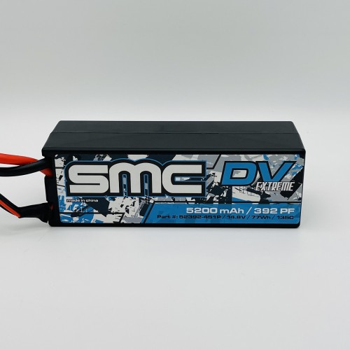
SMC Battery
The battery you will be using is a SMC 14.8V 5200mAh 135C Battery.
Definitions
- Battery: A battery is a device consisting of one or more electrochemical
cells with external connections for powering electrical devices.
- mAh: is an abbreviation for milliamp hour and is a unit that measures
(electric) power over time. It is commonly used to measure the energy capacity
of a battery. In general, the more mAh and the longer the battery capacity or
battery “run time.”
- C-Rating: is a shorthand representation of how many amps the cells can
supply on a continuous basis without failing.
- Cell Count: How many cells are in series to make the overall voltage of
the pack. In this case, 4 cells are in series to make 14.8V nominal, or 16.8V
when fully charged. Sometimes referred to as a 4S battery, the “S” refers to
“series” to tell us how many cells are comprising the battery pack.
The Charger: Hitec RDX1 Pro
The RDX1 Pro is one of Hitec’s most popular single-channel
multi-chemistry battery chargers. It features a 100W Power supply
as well as an integrated 6-cell balancer. The RDX1 Pro is capable of
charging 1S-6S batteries.
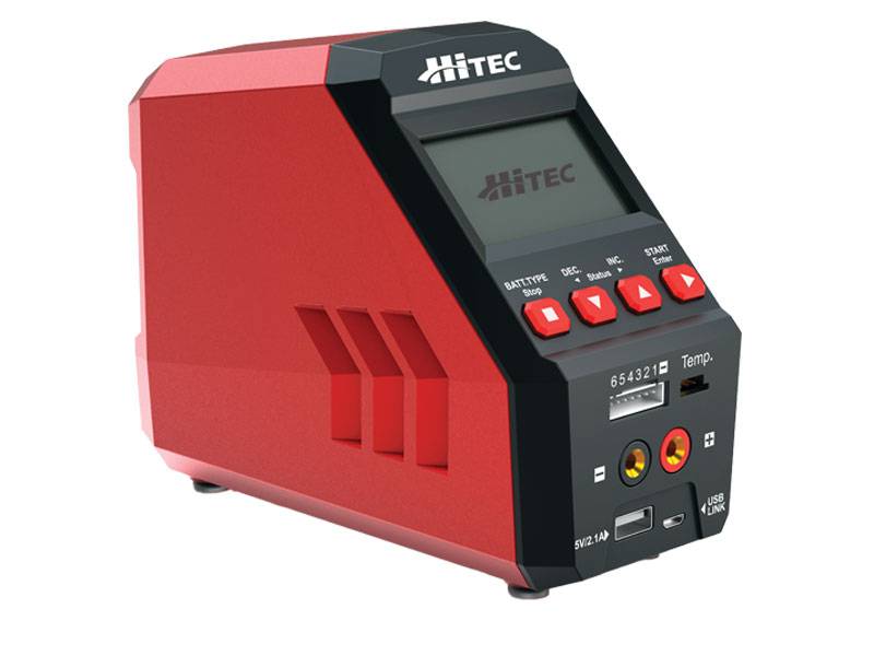
Hitec RDX1 Pro Charger
Battery Storage Bag
Your kit includes a battery storage bag that can be used for storage, transport, and charging.

Lipo storage bag
We recommend you use this bag as a charging mat,
this will give you an added layer of protection between the battery and
the charging surface. Always remember to charge batteries on a
non-combustible surface.
What to Do in Case of Fire
If you follow the safety guidelines provided, you
should be perfectly safe. However, in the event that something has gone wrong,
and there is a battery (LiPo) fire, take the appropriate steps:
Warning
Please read this section, battery fires are serious.
Just look up videos of LiPo fires to see for yourself.
- First, get yourself and those around you to safety.
Drones, computers, etc. are replaceable, while you (and your lungs) are not.
Battery fires produce very toxic smoke, and you do NOT want to breathe it in.
- Get help. This depends on your specific situation, but this may be to pull a nearby
fire alarm (contrary to popular belief, pulling the alarm does not set off
sprinklers), call 911, or call your security department.
After doing the above two steps, and only if you’re comfortable with it and does
not pose any danger to you, you can attempt to fight the fire. Your most effective
tool is a class D fire extinguisher. These are special fire extinguishers that are
meant to put out combustible metals (such as Lithium) and stand out as
being bright yellow.
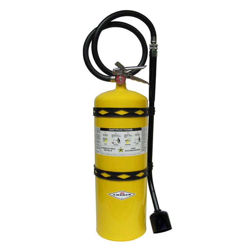
Example class D Copper powder fire extinguisher
However, class D fire extinguishers tend to be uncommon.
If a class D fire extinguisher is available, pull the safety pin, aim the nozzle,
and squeeze the handle. These tend to be quite heavy, so you may need an additional
person to assist.
If a class D fire extinguisher is not available, your next best bet is to throw
a fire blanket over the fire to smother it as much as possible. This won’t put it out
but it will supress the flames. Most labs have a fire blanket.

Example fire blanket
Finally, as a last resort, pour sand or dirt on the fire.
This is generally what we have on hand at competition events for safety and acts
similarly to a fire blanket.

Low-tech solutions can be effective
A normal, red, class ABC fire extinguisher does very little to put out a battery fire.
Don’t waste your time unless you have absolutely nothing else to smother the flames with.
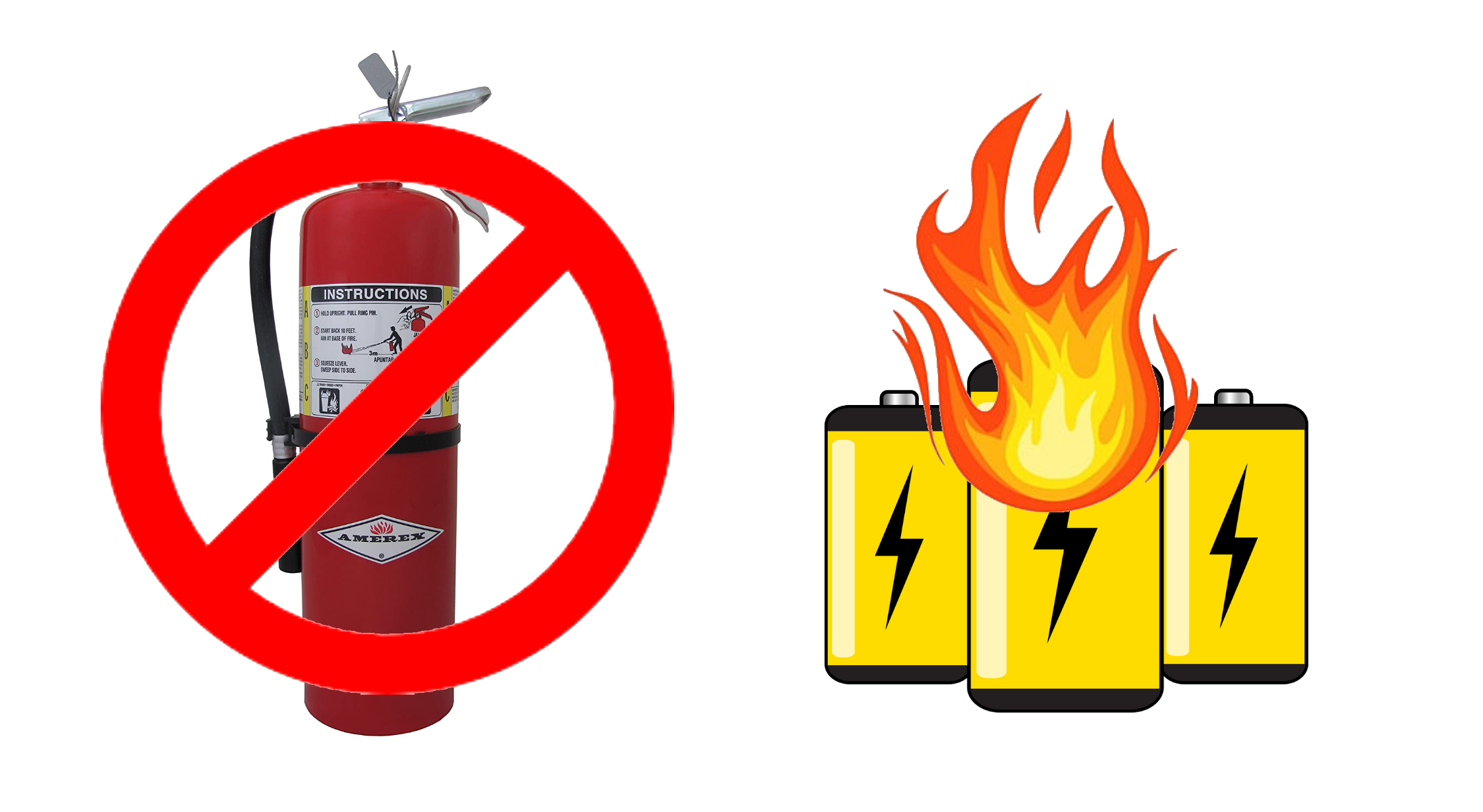
A class ABC fire extinguisher is not effective for a battery fire
5.2 - Charging
Understand how to connect the battery, your charger settings, and how to complete a successful charge.
Charging the Battery
Please read the manual prior to beginning your first charge.
The manual comes with your charger or you can find a
digital version here.
Please watch the video below to understand the recommended LiPo charging process.
Warning
The balance connector should always be used whenever the
battery is being used with the charger.
Note
While the battery has a capacity of 5200mAh, you will likely not put 5200mAh
into the battery on charging. We can only put in what we have taken out.
A LiPO battery cannot be run down to 0.0V per cell, it cannot go lower
than 3.0V per cell without being damaged.
5.3 - Storage
Battery storage is just as important as battery usage. Make sure to follow these steps to keep your battery safe and prolong its life.
Battery Storage
After using the battery, give it approximately 30 minutes to cool down.
Determine when the battery will be used going forward. If the battery will be used
again within 24 hours, proceed to fully charge the battery.
The goal is to minimize the time lithium batteries sit fully charged.
Long periods of maintaining full charge will dramatically reduce the lifespan
of the battery pack, and can lead to swelling/premature failure.
If the battery will not be used in the next 24-48 hours, please proceed with a
storage cycle, as demonstrated in the video below.
Note
Storage charging may take hours to perform properly based on the
starting voltage of the pack. A storage cycle should never be conducted
without direct supervision. In cases where the time for a proper storage
cycle cannot be committed, leave the battery in a discharged state rather
than taking a chance and leaving it unattended while on the storage cycle.
The storage voltage range is typically between 3.70-3.85V per cell.
However, lower voltages, down to 3.4V per cell are unlikely to cause issues,
especially over shorter time periods. If the battery will be in storage for more
than a week, it’s best to perform a proper storage cycle as time permits.
6 - RC Transmitter Setup
This section provides instructions on how to configure the FlySky FS-i6S RC transmitter that is included in the AVR drone kit.
Setup
The FlySky FS-i6S RC transmitter is a highly configurable radio controller with a
touch screen, supporting up to 10 control channels at the same time.
In order to use it with the AVR drone, some setup is required, both for the
RC transmitter and for the FC. On this page, we will go into detail on how to
set up the RC transmitter so that it can be used to safely control the drone.
The radio controller box should include a quick start guide. A
more detailed user manual for the radio controller is available for download below.
The following sections will cover numerous aspects of the transmitter configuration
required to fly your AVR drone.
6.1 - Basic Usage
Overview
To turn on the transmitter, press and hold the two power buttons on the front of
the device until the screen lights up. After you see the logo, you will be presented
with the home screen.
You might see a warning when you turn on the transmitter about switch positions.
Just follow the instructions provided on the screen to continue to the home screen.
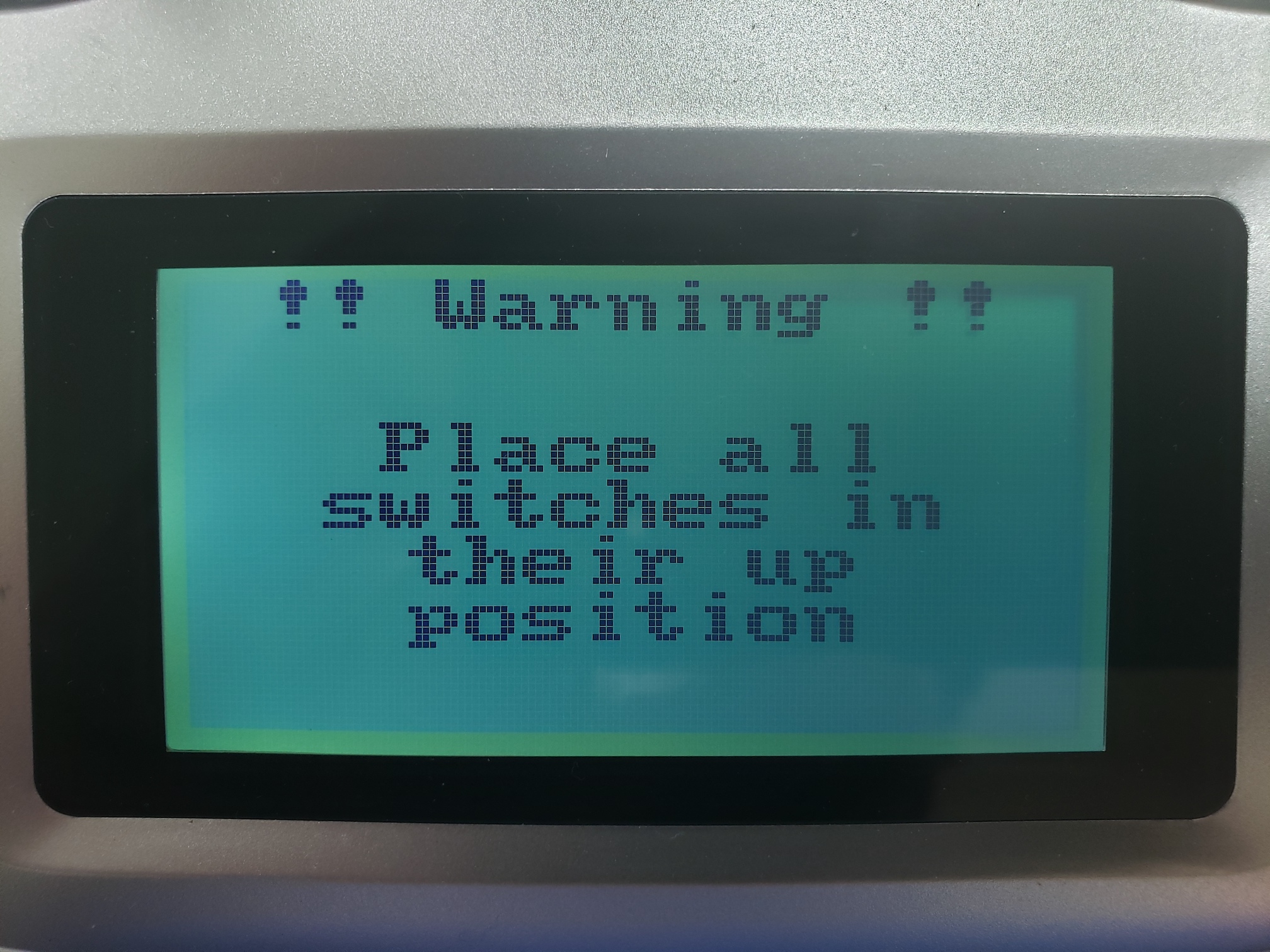
Make sure all switches are in the up position to continue to the home screen
The transmitter contains a touch screen used for displaying status info and for setup
purposes. The home screen has three different views. You can switch views by swiping
left and right, where the bottom indicator shows you which screen you are on
(when you start the transmitter, you see the center screen).
Home screen of transmitter
The left screen shows you the current value sent over all channels,
while the right screen shows information about sensors connected to the transmitter.
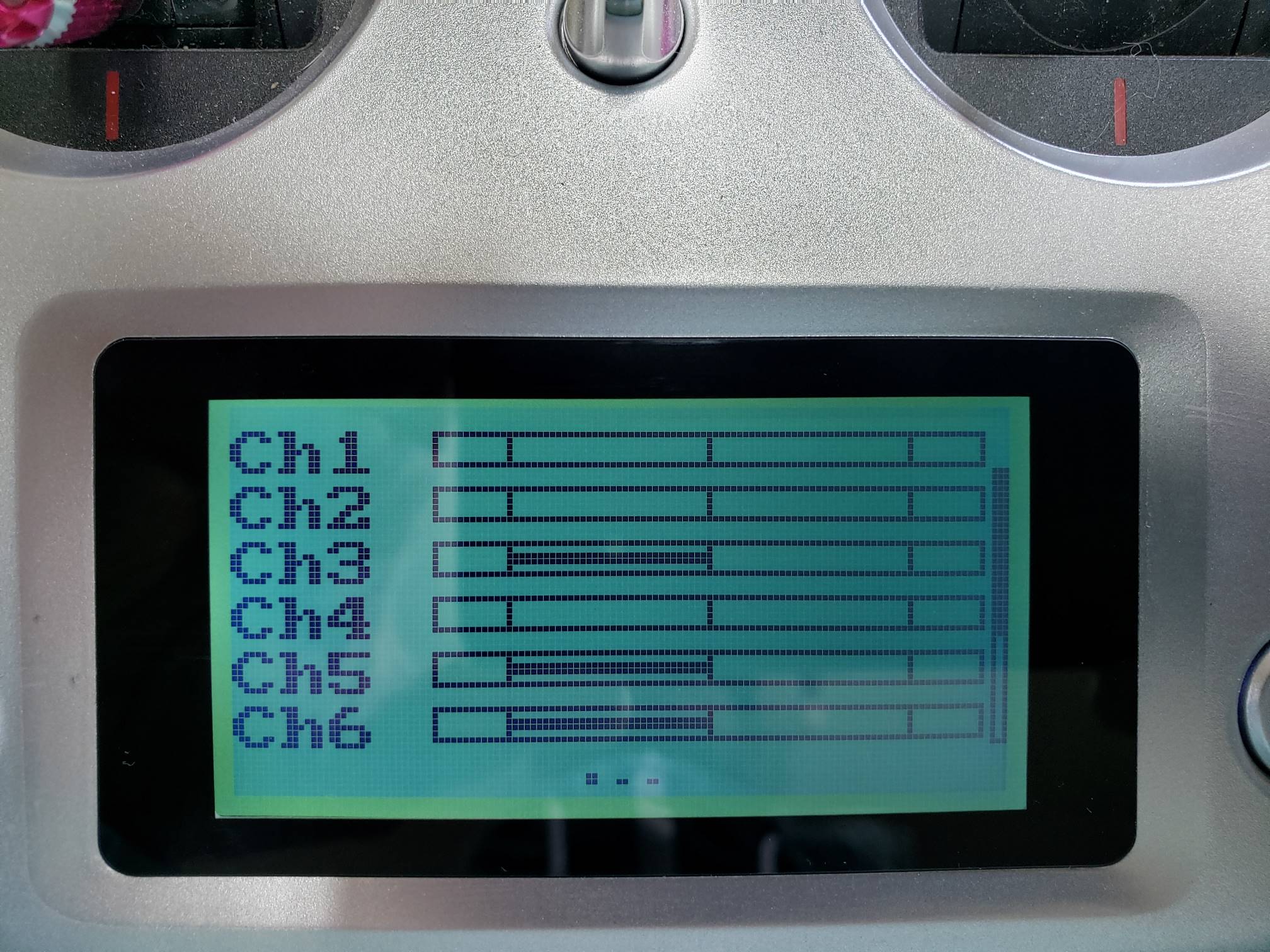
Left screen showing channel values
One thing that is helpful to gain an understanding of how your flight sticks
map to various channels is to swipe to the channel view and move your sticks around.
You should see the channel values update as you move the left and right sticks.
Screen Unlock
By default the transmitter settings will be locked which prevents you from accidentally changing a setting. To unlock the screen press and hold the lock icon for 2 seconds.
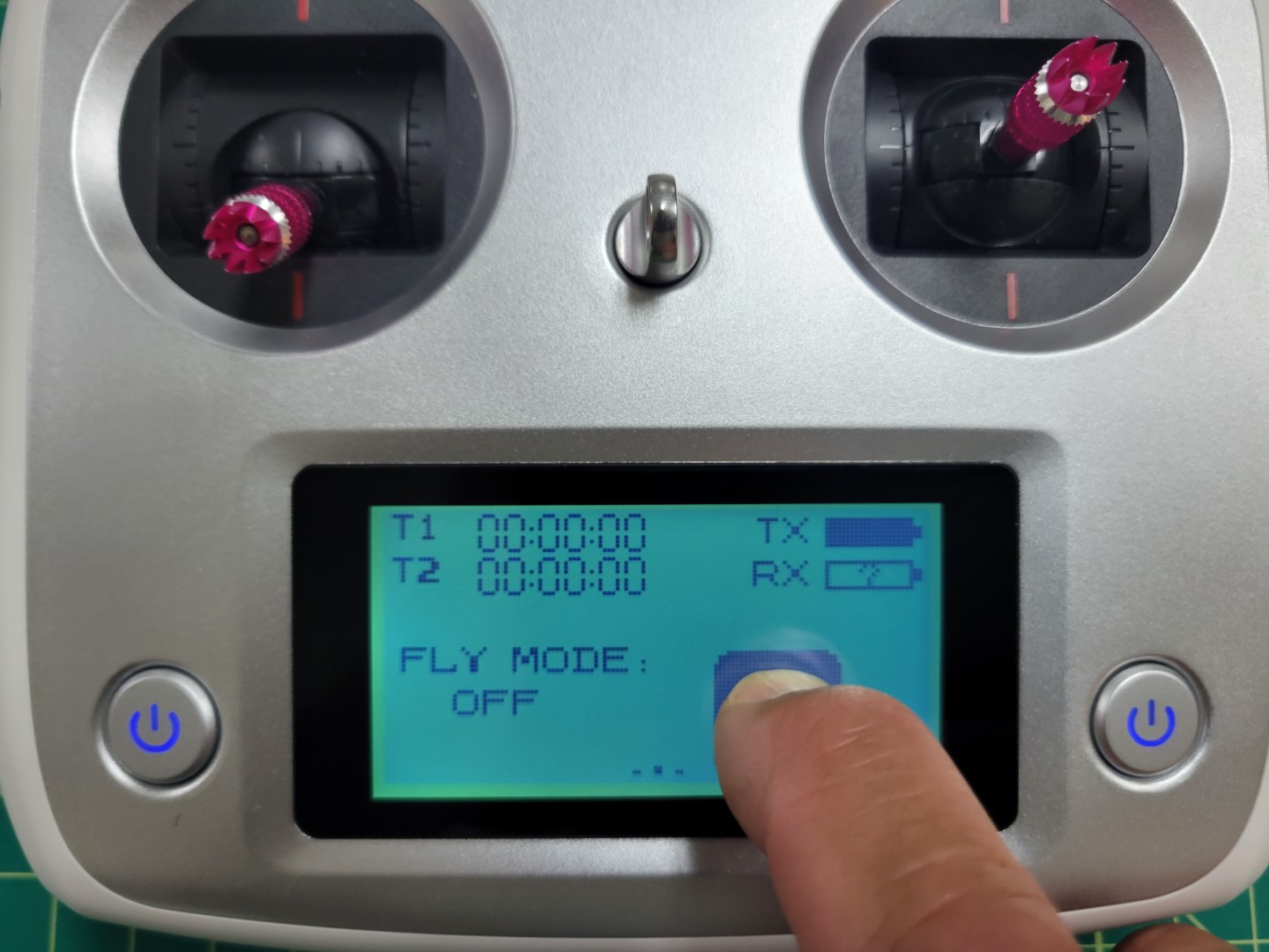
Press and hold 2 seconds to unlock
After unlocking you will see the settings icon with the wrench and screwdriver.
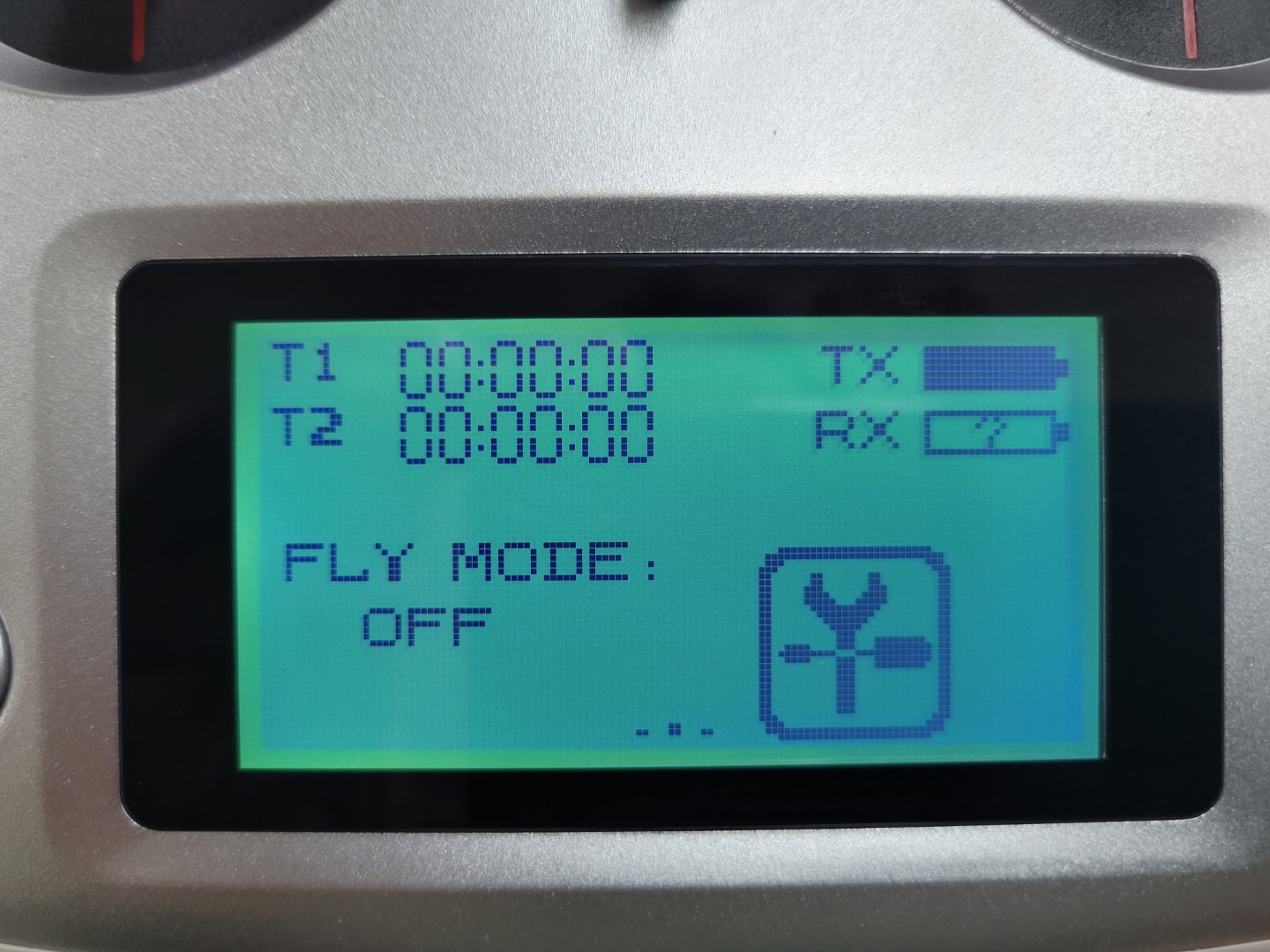
Settings icon on home screen
Configuration
Configuration is done by pressing the settings icon. The next screen has two different views: the
function view and the system view. The function view provides options that
change how the different sticks, buttons, and dials on the transmitter are
transformed to channel values.
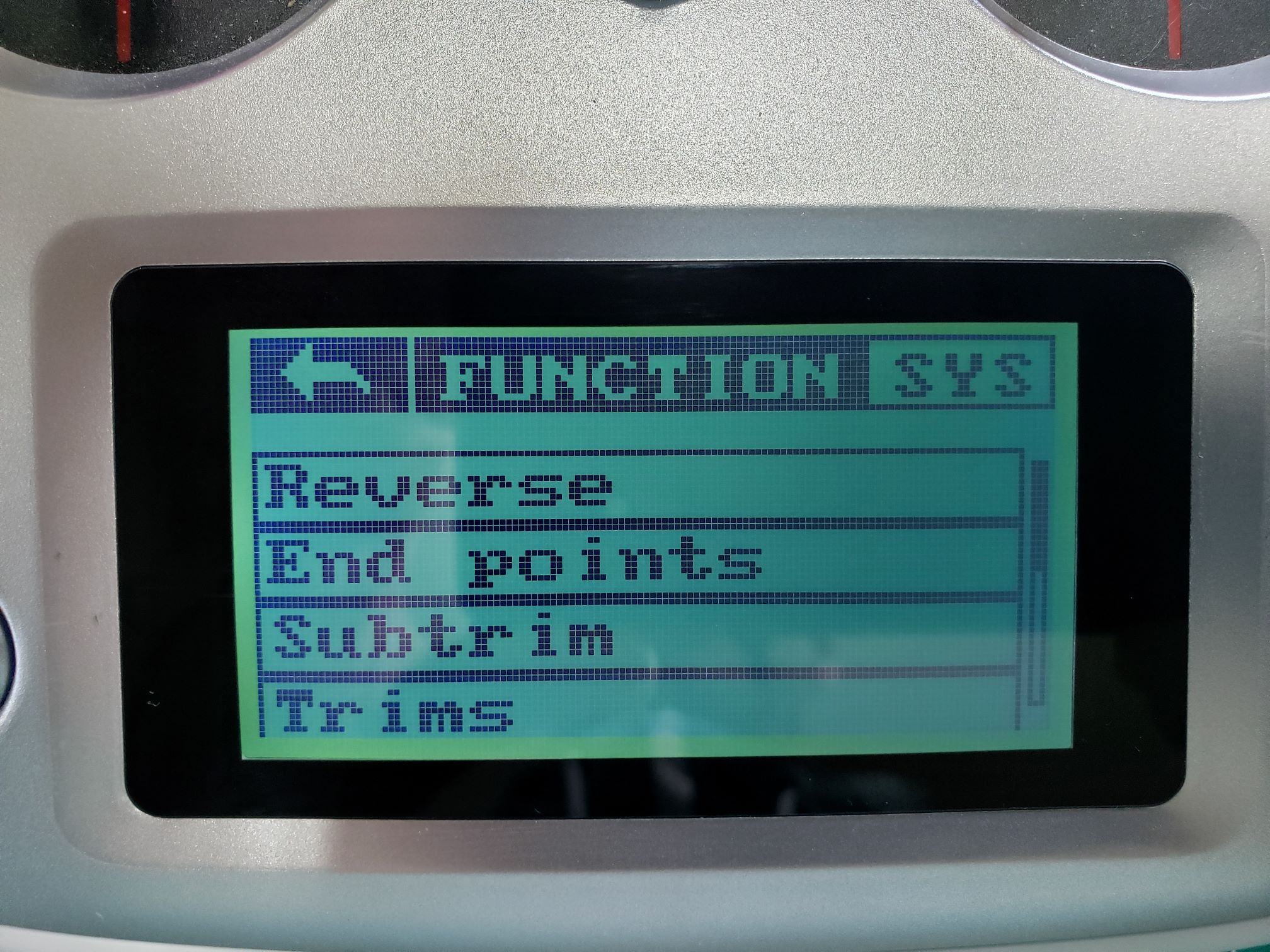
Function view
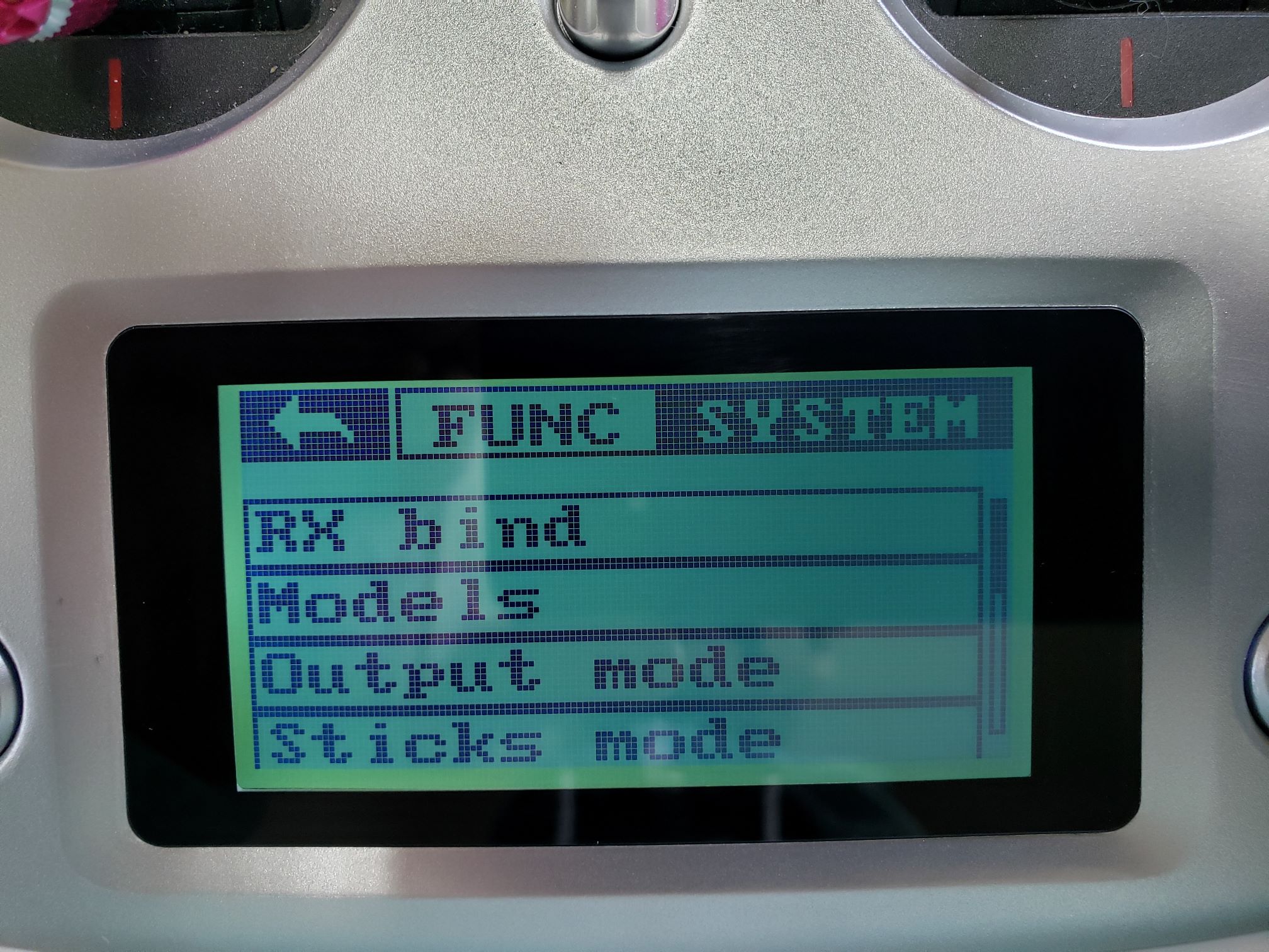
The system view provides options for setting up the transmitter itself.
You can change to the system view by pressing SYS.
System view
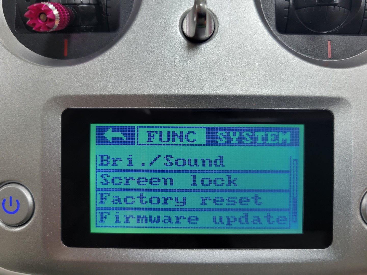
Screen Lock Timeout
You will likely find that the screen lock timeout of 5 seconds is way too short. We recommend changing this to 5 minutes while you’re becoming familiar with the transmitter. You can do this by going to the system menu and selecting screen lock.
Screen lock in system menu
You have several screen lock timeout options. Select the one you’re most comfortable with.
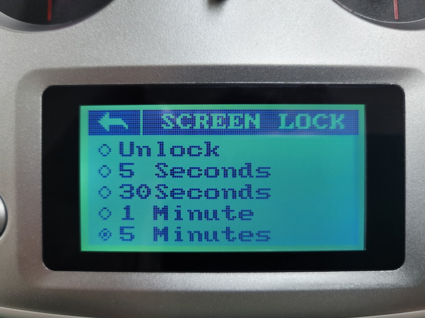
Screen lock timeout
6.2 - Binding the RC Receiver
The RC receiver module has already been installed on the drone in a previous step.
Please verify that it is correctly connected on both the receiver (RX) side and on
the FC side as shown in the photo below.
Aside from the physical connection we also need to establish a wireless connection
between the transmitter and the receiver. This wireless connection happens through a
process known as binding. Binding is what will allow us to control the AVR drone
with the transmitter and change flight modes, which will become important in
the competition.
Out of the box, the receiver and transmitter should be automatically bound
to each other. If this is the case, the RC transmitter display would look
similar to the picture below when both transmitter and receiver are turned on
(receiving power). Please note the RX battery bar.
If this shows a question mark (while the receiver is getting powered),
then you will need to go through the binding process. We will cover that shortly.
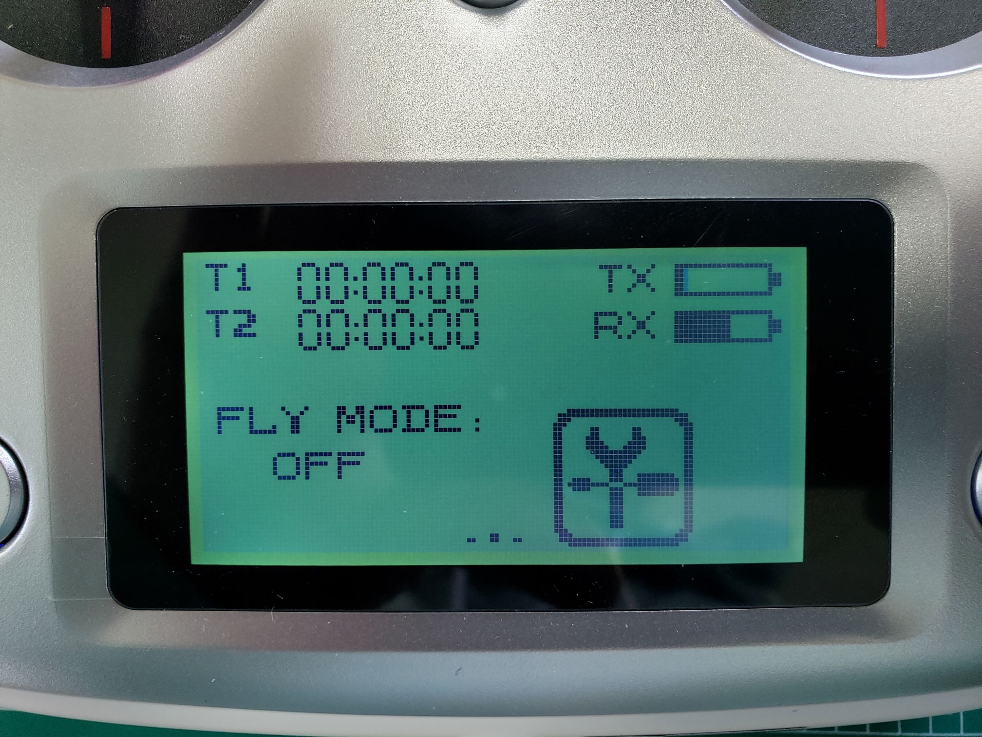
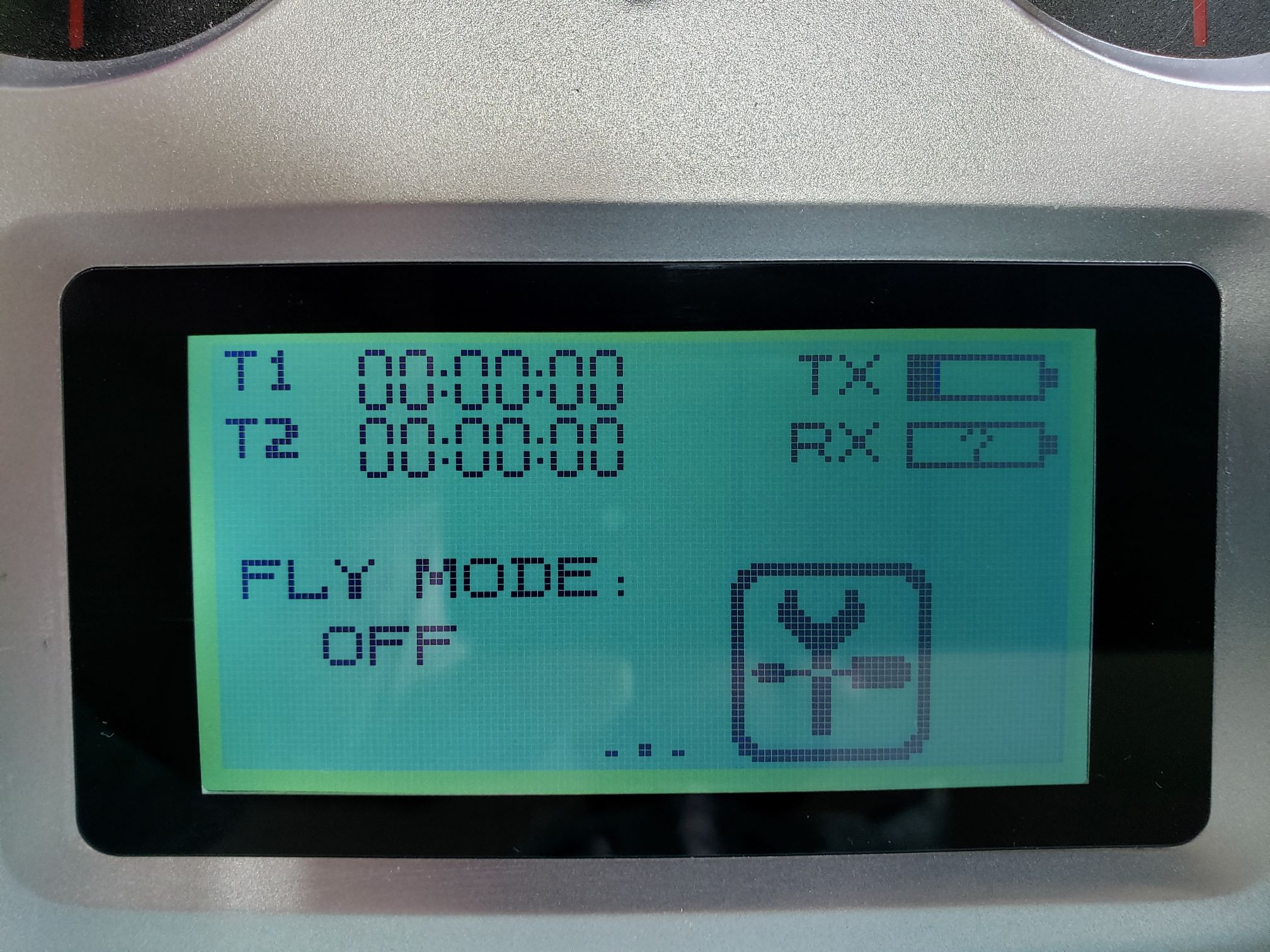
TX main screen showing RX connected
The TX battery bar shows the remaining capacity of the batteries in the transmitter.
However, the RX battery bar does NOT actually show the battery
capacity of the drone. It reports a reading of the voltage level
(between 4.0 and 8.4 V) that is provided to
the receiver module by the FC, which should always be 5.0 V. In our case, it is only
useful for verifying that the transmitter and receiver module are
communicating with each other.
If your transmitter and receiver are already bound you can skip to the next
section labeled Setting the Output Mode. If the transmitter and receiver
are not bound, you can do it yourself. Make sure the FC is not powered by the
battery or USB cable. Insert the bind plug in the rightmost vertical slot
(labeled B/VCC) on the receiver module, see the picture below. You will find
the bind plug in a small plastic bag in the transmitter box. The cable that
connects to the FC should remain as shown below.
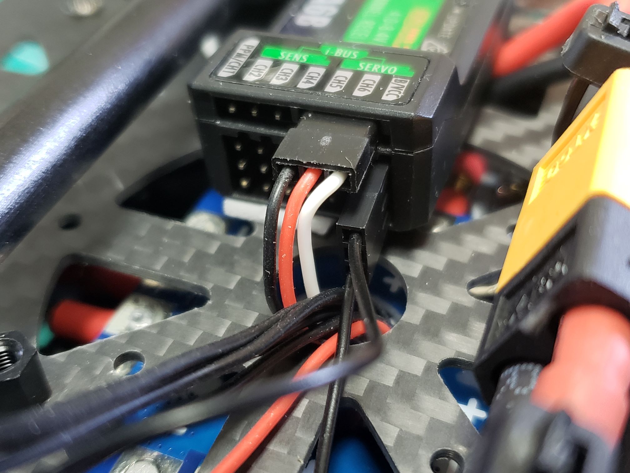
Receiver with cable going to FC (black/red/white) and bind plug in B/VCC slot
Turn on the transmitter and go to the system view in the settings menu.
Select RX bind. It will wait for the receiver to be turned on in bind mode as well.
You should now power the FC, which will also power the RC receiver module.
The easiest way is to power the FC with a micro-USB cable. When power is provided,
the receiver module will go into bind mode because of the jumper wire.
The binding procedure should be finished automatically (you might not even notice).
Power everything down and you should now remove the bind plug
from the receiver module. It should not remain in the receiver as it will
trigger the binding procedure again every time the receiver module is powered.
The next time you power up your transmitter and receiver they will be communicating.
6.3 - Setting the Output Mode
In the world of drones and radio controllers, there are a lot of different protocols
in use. More information about these different protocols can be found
here.
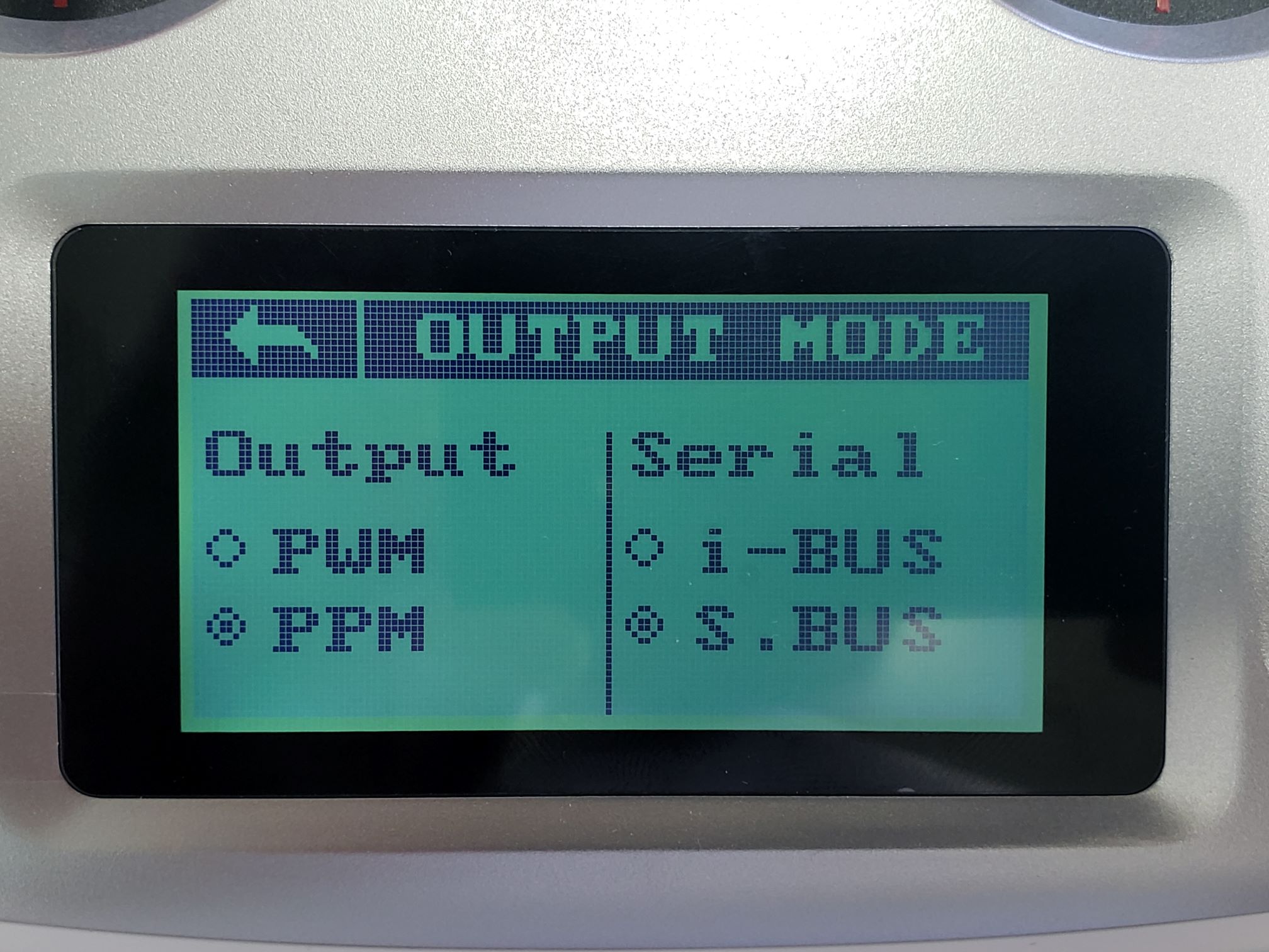
The FlySky FS-iA6B receiver that was included with the FlySky FS-i6S transmitter
supports PWM, PPM, S.BUS, and i-BUS output, but the FC in the AVR kit only supports
PPM and S.BUS. For the AVR drone, it is recommended to use the S.BUS protocol since
it is the most stable of the two and supports more channels.
Configuring the RC receiver to output the S.BUS protocol can be done in the
OUTPUT MODE screen shown below. You can find the
OUTPUT MODE screen on the system view in the settings menu.
Everything should be configured as shown in the picture.
This will set PPM and S.BUS as the output communication protocols, which will be
available on separate pins. The FC has already been connected to the pins on
which S.BUS output will be available.
Output mode configured for PPM and S.BUS
Changes are automatically saved so you can tap on the back arrow to go to the
previous menu. If you power down your transmitter these settings will
still be maintained.
6.4 - Setting Up Channels on the RC Transmitter
The receiver module supports up to 10 channels when using the S.BUS protocol.
The first 4 channels are used for basic control with the transmitter sticks,
leaving several free channels which can be mapped to auxiliary control switches.
Assigning switches, dials, and buttons on the transmitter to channels can be done
using the Aux. channels option under the Function tab in the Settings menu.
These channels will be useful throughout AVR and will let us do things like toggle a
switch to change the current flight mode of the drone.
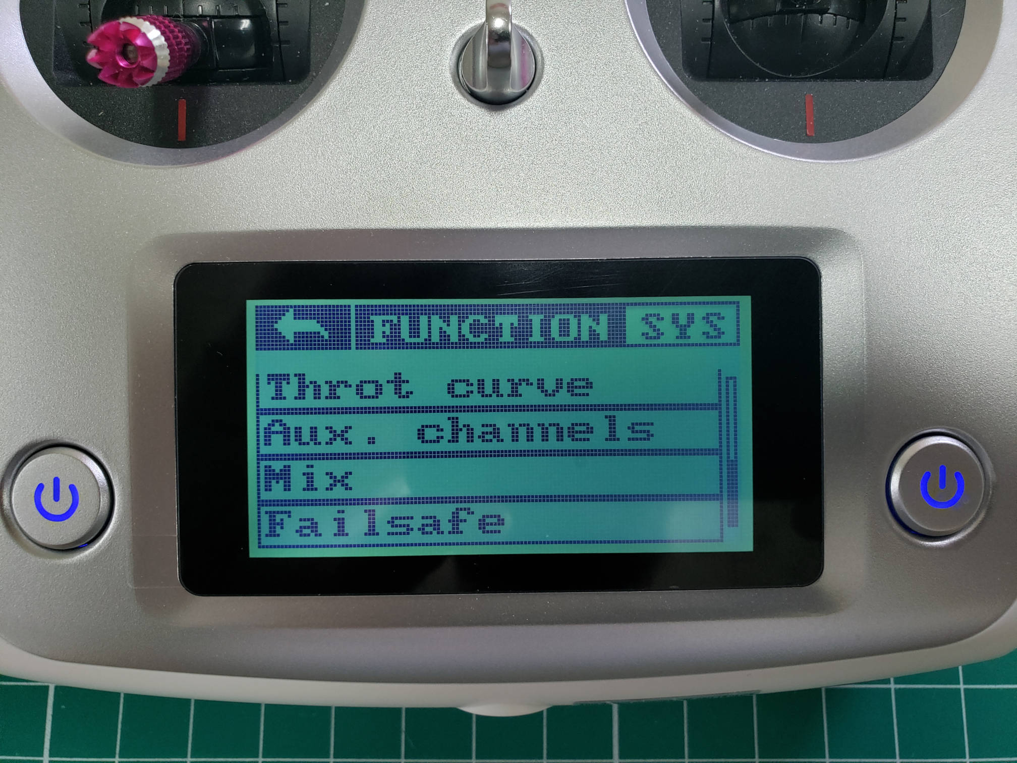
Auxiliary channels in Function menu
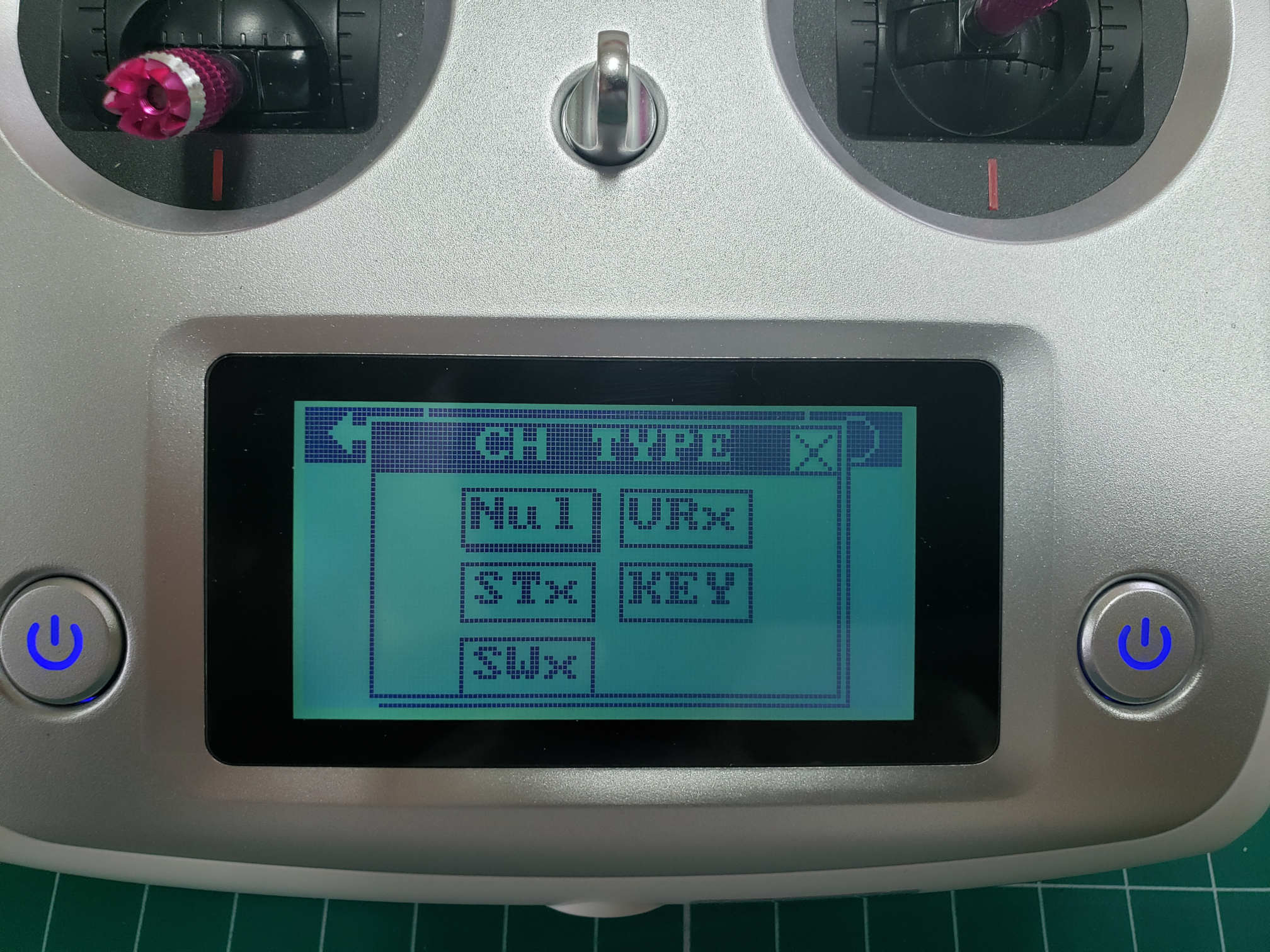
You can press the icon to change the kind of input
(STX = stick, SWX = switch, VRX = dial, KEY = button). Pressing the text label
you can specify which exact input should be mapped to the channel.
It is also explained in
section 6.7 of the transmitter manual.
For the AVR drone, we provide a default channel setup which allows for maximum
utility of the available channels, which can be found below. In future references,
we will always use the channel setup as provided here.
| Channel |
Switch |
| 5 |
SWA |
| 6 |
SWB |
| 7 |
SWC |
| 8 |
SWD |
The following steps will walk you through assigning Channel 5 to SWA.
First, tap on the big circle with the line through it.
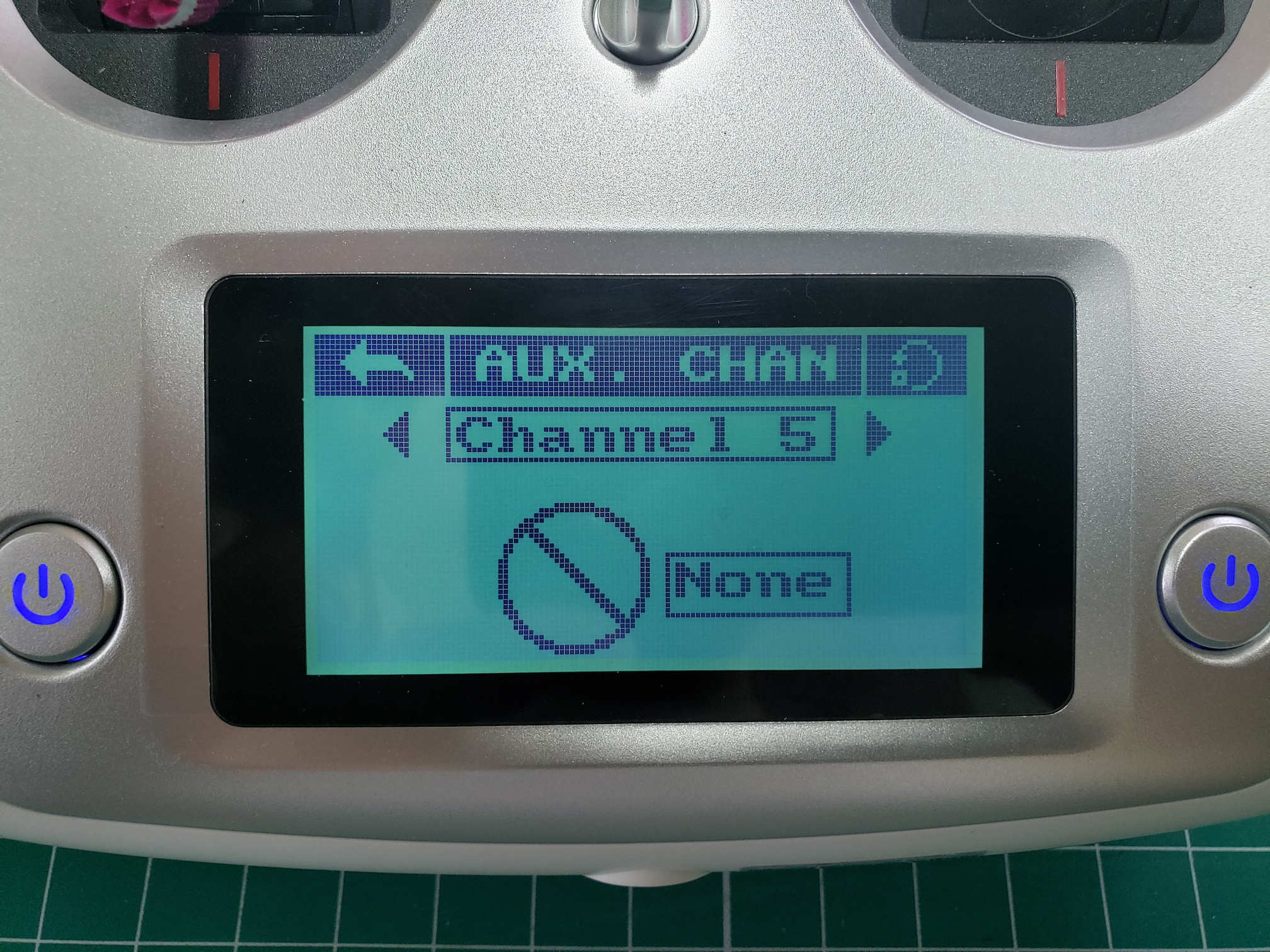
Channel 5 setup
The following screen allows you to assign CH5 to a switch. You will select SWx.
Assigning a channel to a switch
After selecting SWx you will be presented with a screen that lets you select one
of the following switches: SWA, SWB, SWC, or SWD for Channel 5.
In this case, we will select SWA.
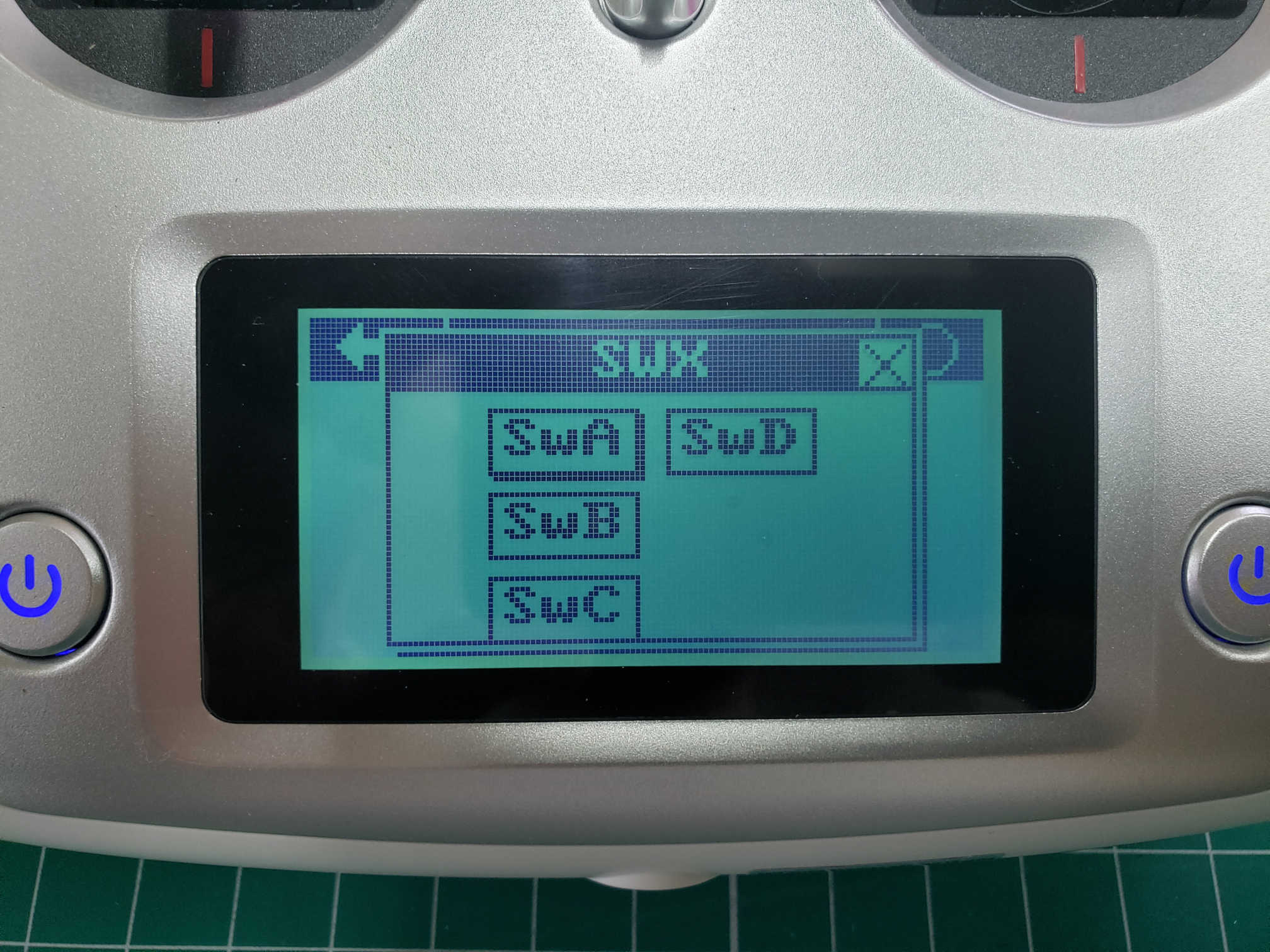
Select SWA for Channel 5
Repeat these steps for CH6, CH7, and CH8 based on the table above.
After completing the steps you can go back to the home screen and swipe
right to see your channel outputs. Swipe down to see CH5 - CH8 outputs.
With all switches in their default position (up) you should see the output
as shown in the image below.
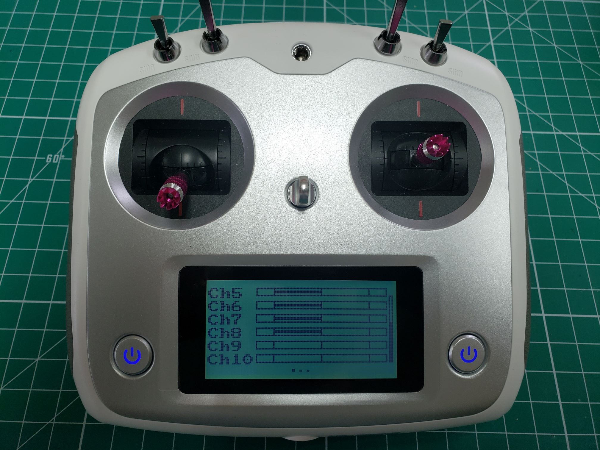
Default output for CH5-CH8 - all switches up
Now toggle all of your switches to the downward position.
You should notice that the output changes and should be identical to the image below.
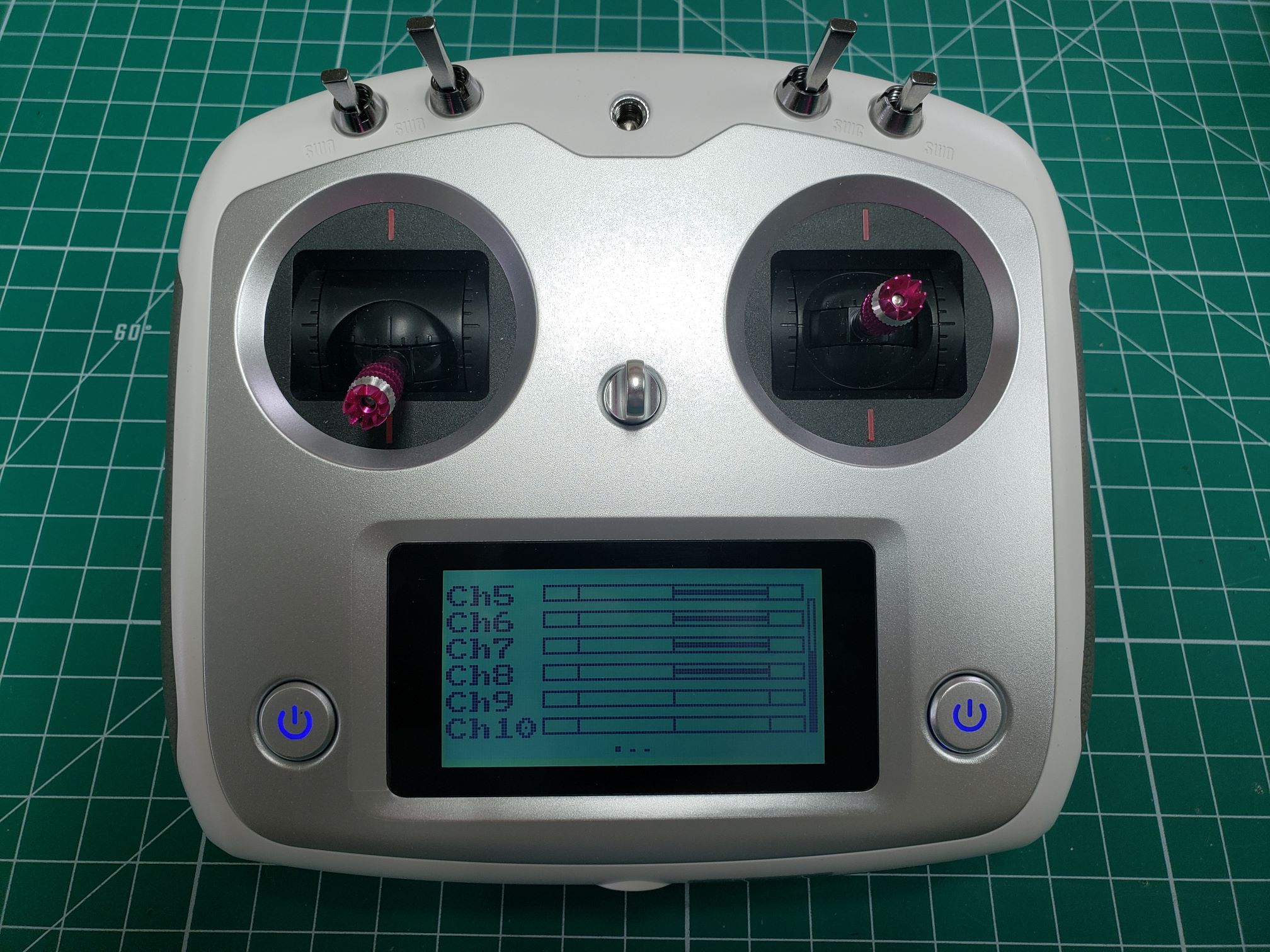
All switches toggled down
6.5 - Setting Up Failsafe
By default, when the RC receiver loses connection with the transmitter,
the receiver will continue sending the latest known stick position to the FC.
While this can be useful in some situations, it is very dangerous for flying drones:
it can result in fly-away situations whenever signal is lost! To change this, the
failsafe option in the function tab of the settings menu can be used. It allows us
to set a desired value for each channel to take on whenever the transmitter loses connection.
Warning
Setting up proper fail-safes is very important for your own safety and the
safety of your environment! Don’t neglect this, and review your setup regularly!
While the FC should be able to detect signal loss and has different options to
react in such a situation, we also recommend a good failsafe setup on
the RC transmitter, as a last resort in case the FC does not detect the signal loss.
We recommend setting the failsafe options as follows in terms of stick and
switch positions. This will cause the drone to shut down its motors when
the FC does not detect the signal loss. This is the only viable option,
it is not safe to keep the drone in the air when we do not have any control over it.
We will later have a look at failsafe options in the FC configuration as well.
For now, we will set the RC transmitter failsafe to:
- Left stick (throttle/yaw) to the bottom and horizontally centered.
- Right stick (pitch/roll) both horizontally and vertically centered.
- Switches SWA, SWB, and SWC in the upward position, SWD in the downward position.
This will set the throttle to zero and reset the yaw, roll,
and pitch to neutral angles. We will later assign functions to the switches,
where the upper position will be the default state. We will assign a kill switch
function to SWD. With this failsafe setting, the receiver will emulate
the kill switch being flipped when it loses connection, and ultimately
disable the motors.
Default stick/switch positions with SWD kill switch enabled (toggled down)
Note
Channel values are normally represented by a range of -100% to 100%.
For example, the throttle stick (left stick vertical axis) is assigned to CH3.
When the throttle stick is all the way down CH3 is set to -100% and when it
is all the way up (maximum throttle) CH3 is set to +100%.
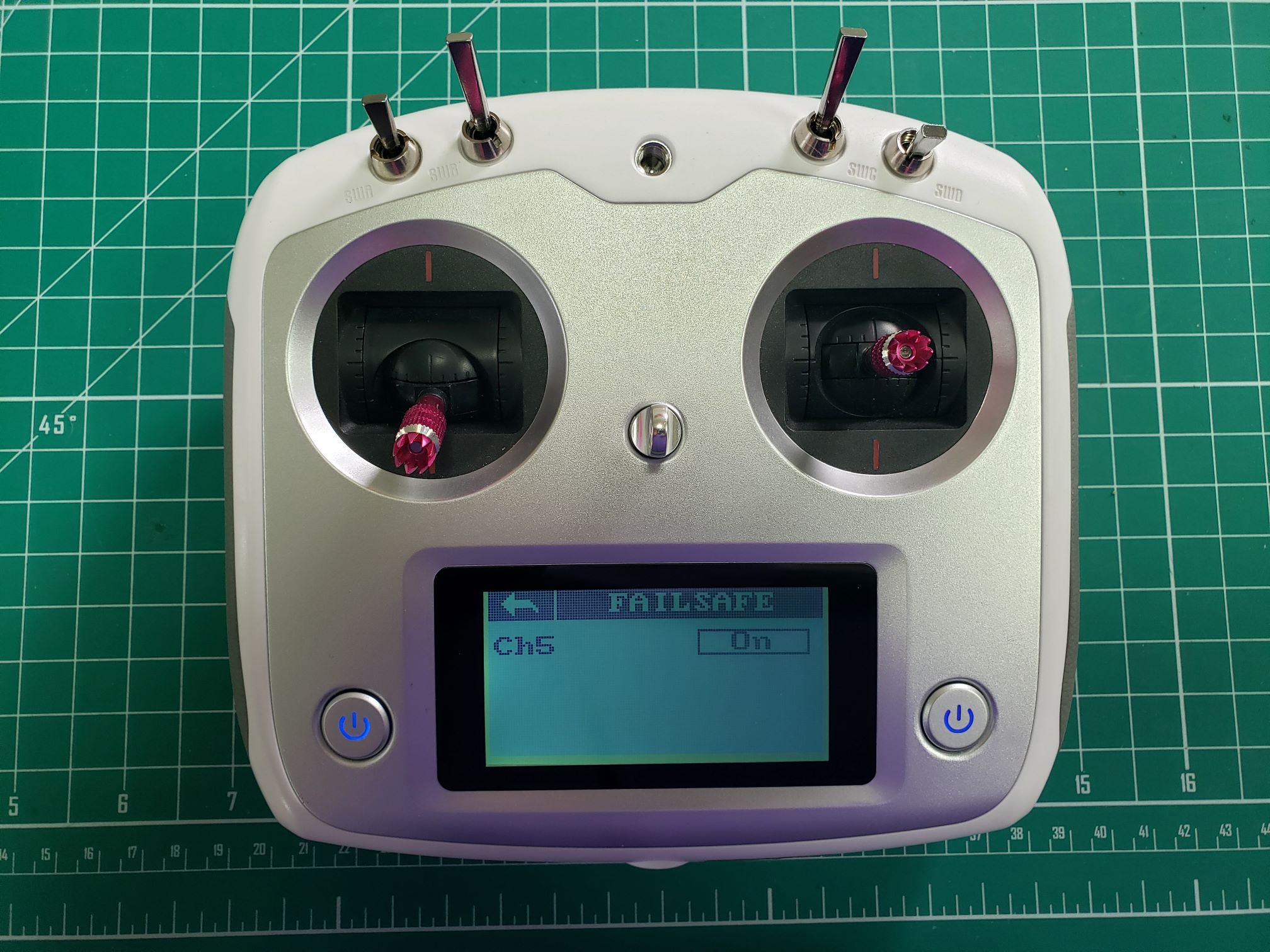
To begin setting up failsafe values, go to the Failsafe screen from
the Function screen in the Settings menu.
Default failsafe screen
To set up a failsafe for a channel, tap the Off button next to the channel.
In the screen that appears, tap the On button to enable the failsafe
for that channel.
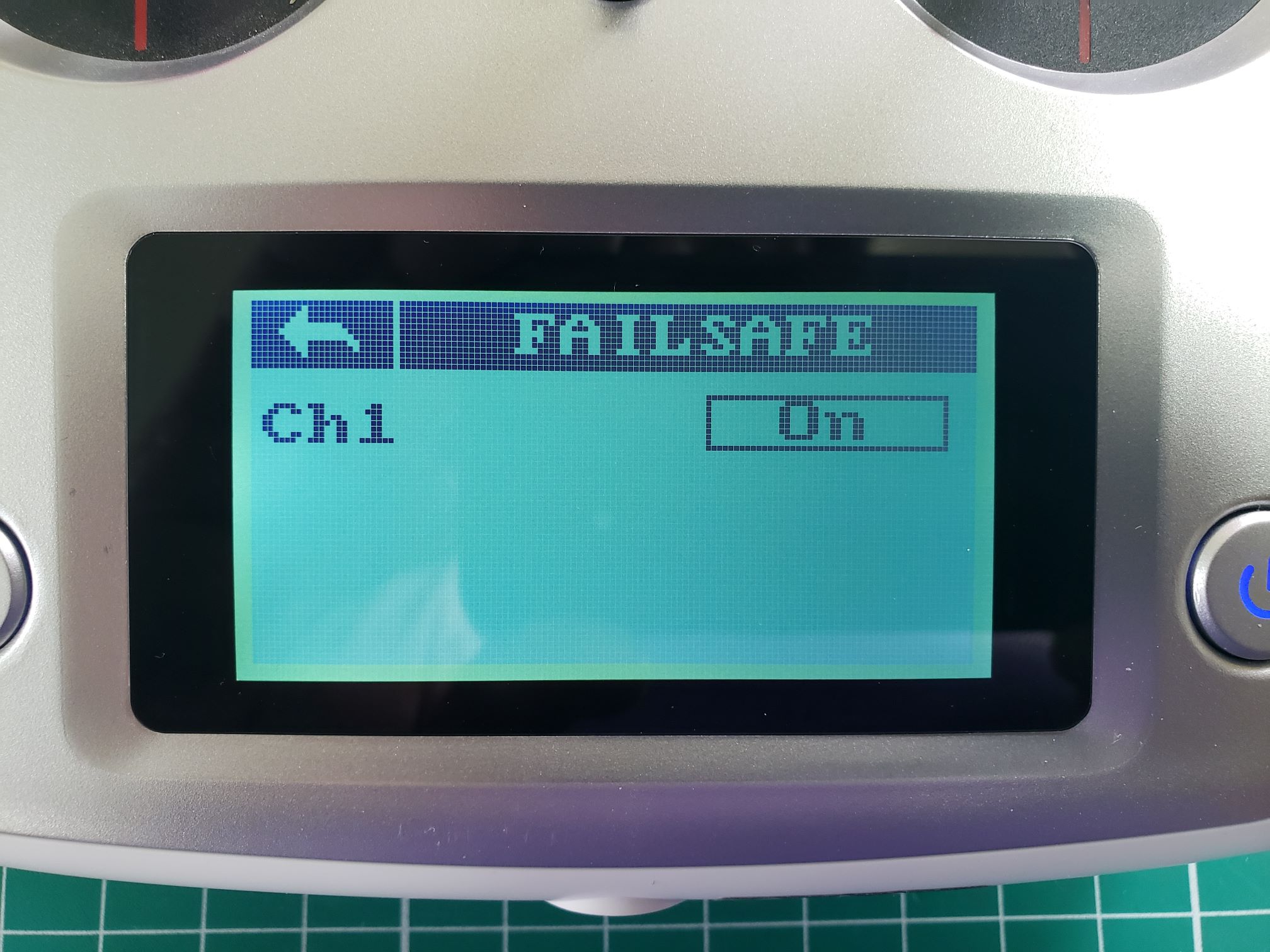
Setting up failsafe for CH1
Now make sure the stick/switch belonging to that channel is in the correct position.
In the case of CH1, which is assigned to the right stick, it will be horizontally
and vertically centered. Now tap the Setup button to save this position.
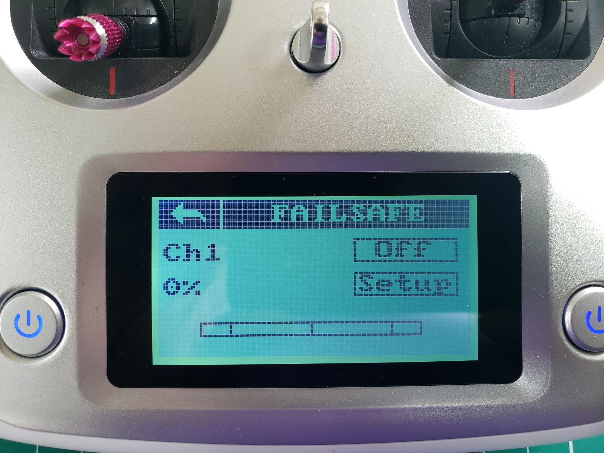
CH1 failsafe value set to 0%
After tapping Setup you will be taken to the main failsafe screen
where you can configure the failsafe for the rest of the channels.
CH1 failsafe value set to 0% (right stick centered)
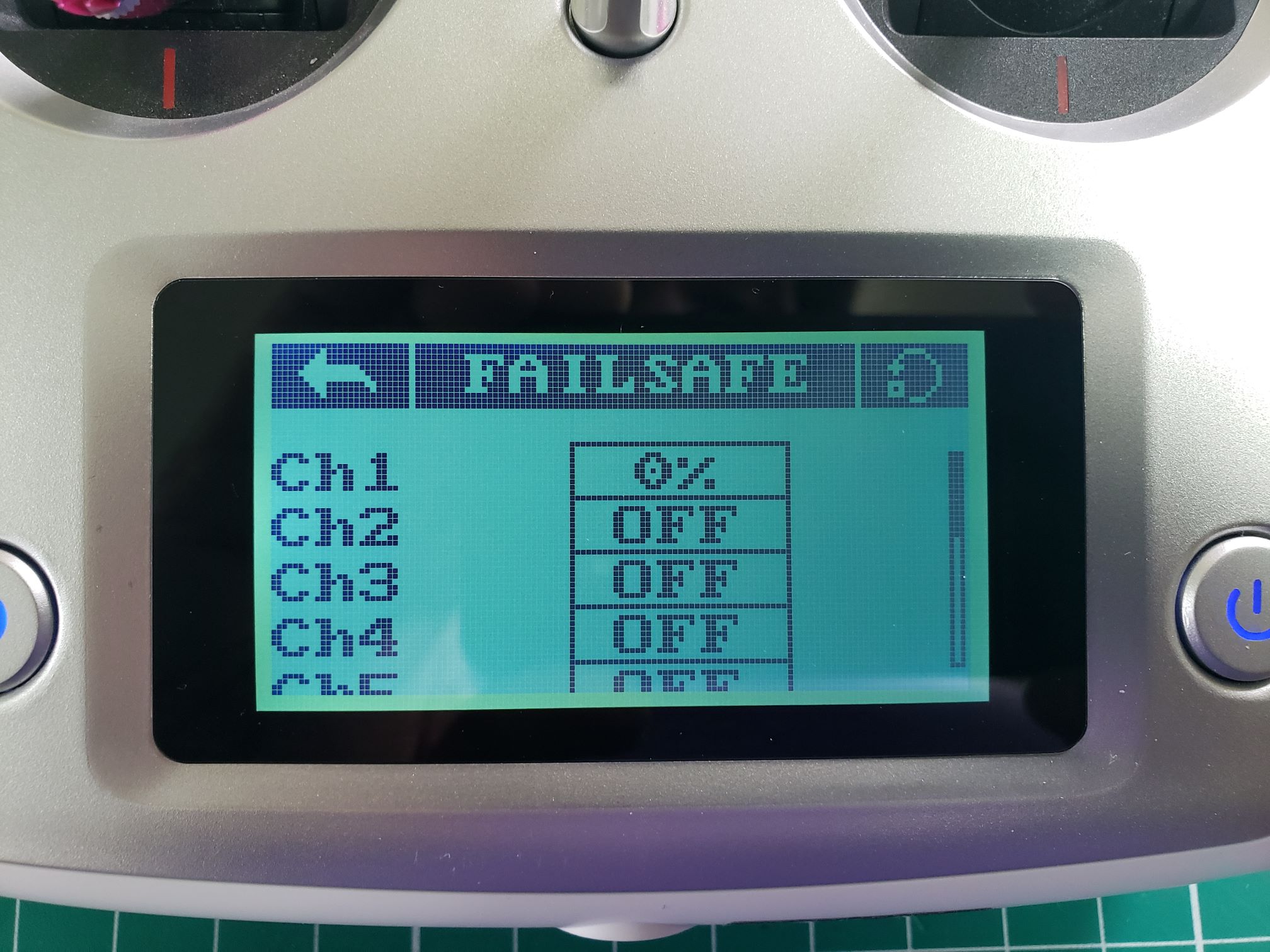
Go ahead and complete the failsafe configuration for Channels 2, 3, and 4.
When finished you should see something identical to the image below.
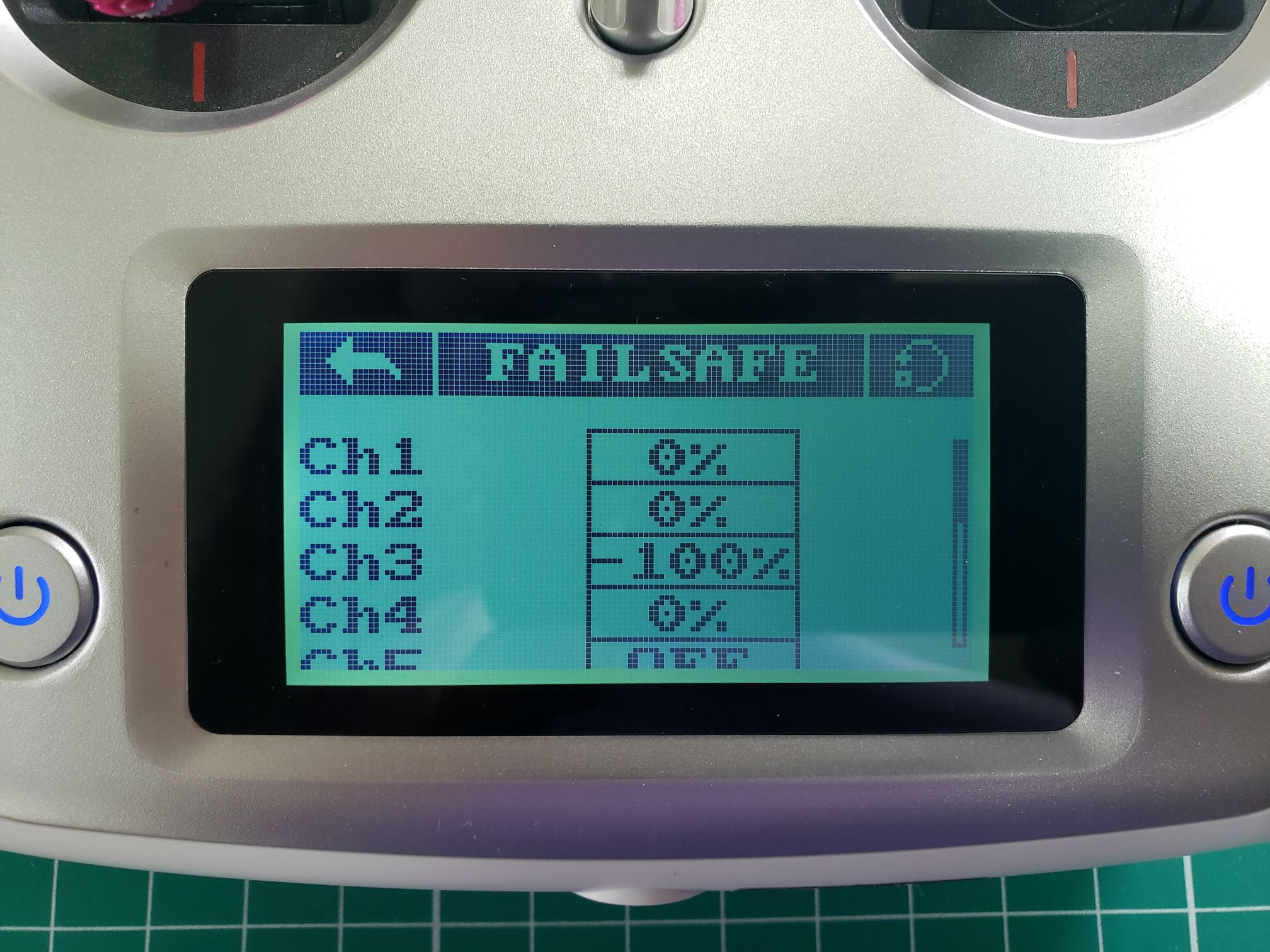
Failsafe configuration for Channels 1-4
We will now set up failsafe values for the switches we configured in
the previous section. Let’s run through an example of doing this for CH5,
which is attached to SWA. Make sure SWA, SWB, and SWC are in
the up position and SWD is in the down position.
Setting up failsafe for CH5 attached to SWA
Tap On and then Setup for CH5. This will set a value of -100%
for CH5 (SWA up position) as shown below.
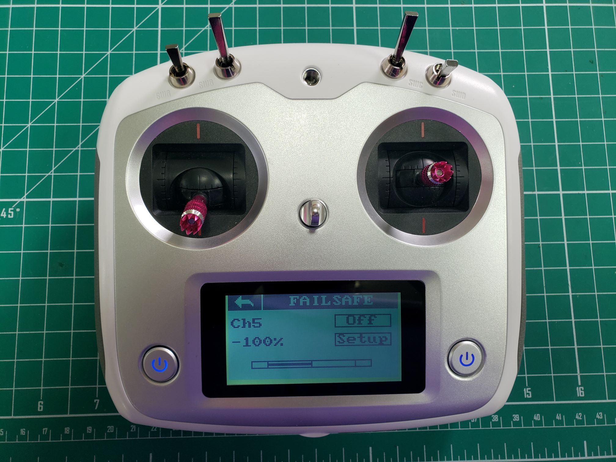
CH5/SWA default switch position up with a value of -100%
Tap the back arrow and complete the process for Channels 6-8.
Keep in mind that since CH8 (switch SWD) is in a downward position the value
will be +100% as shown in the photo below.
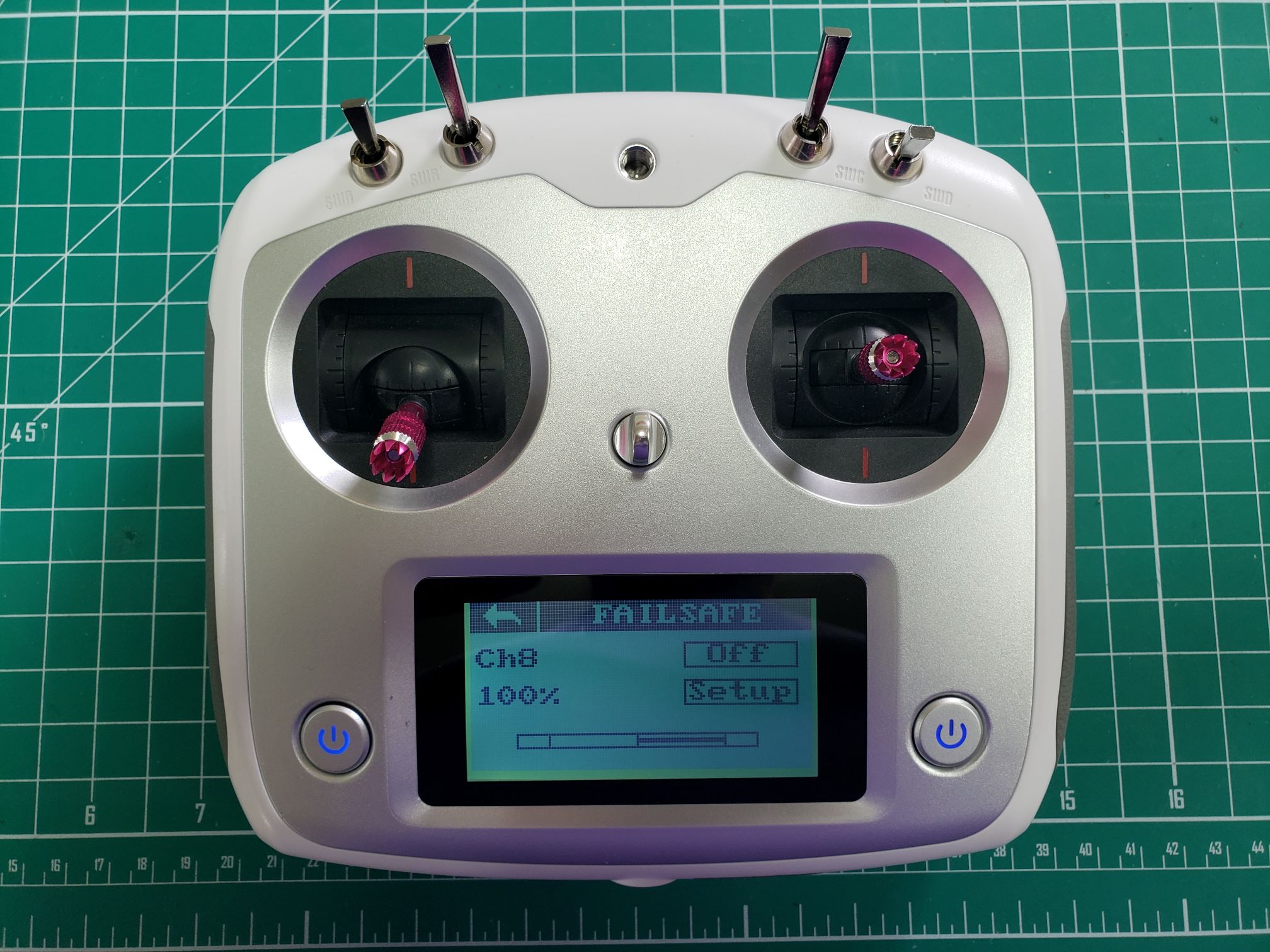
CH8/SWD down switch position with a value of +100%
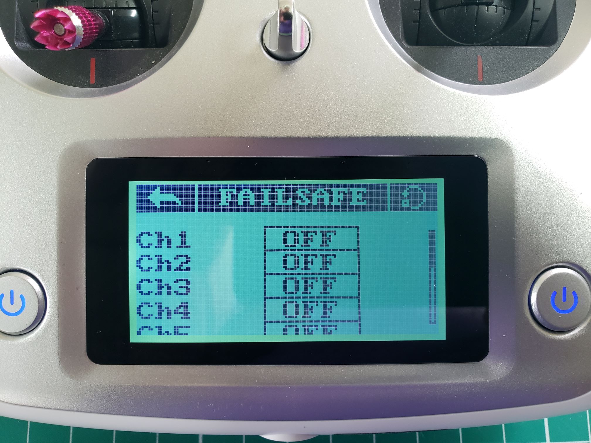
The following photo shows the final failsafe values for Channels 5-8.
These are the values that will be sent from the receiver to the FC in
case there is a loss of signal with the transmitter.
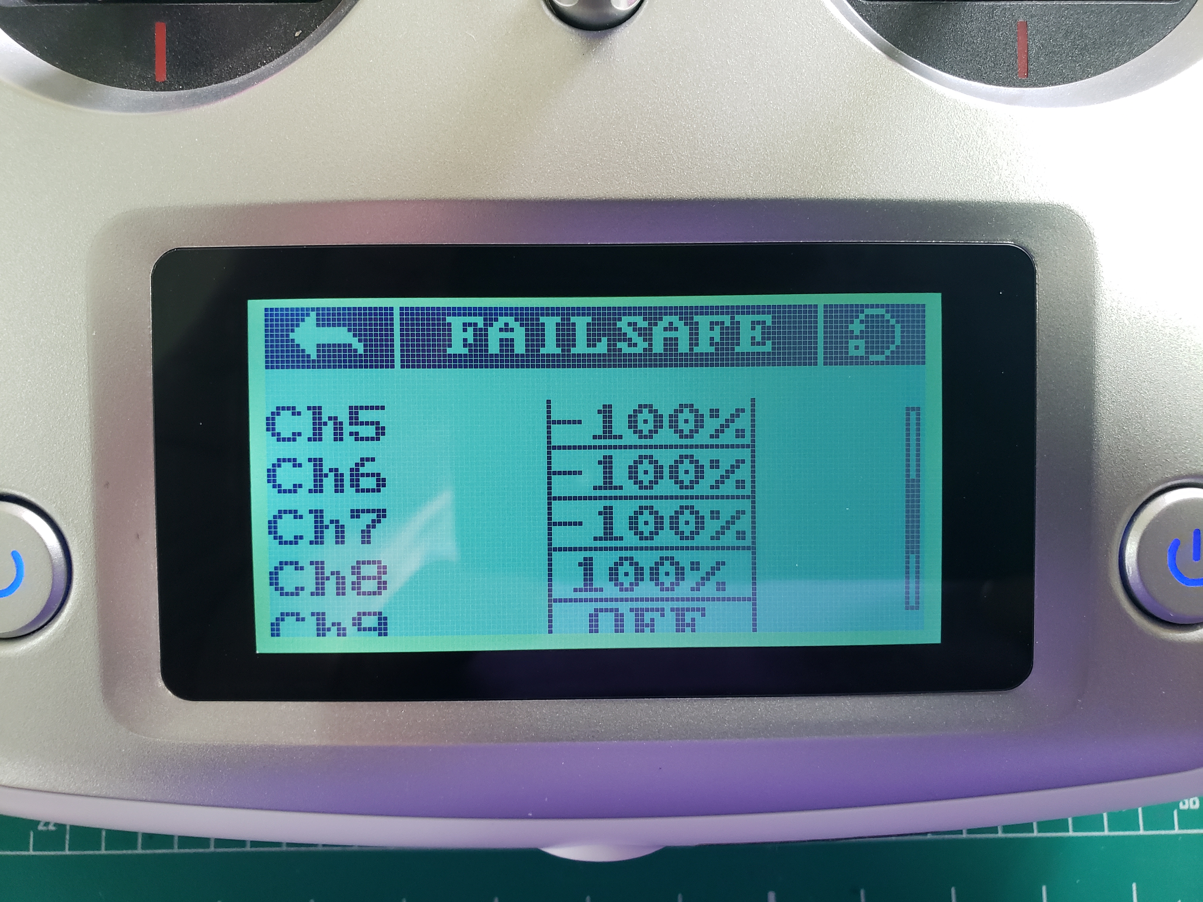
Failsafe configuration for channels 5-8
The failsafe values for all channels have been configured. In the end,
you should have the following failsafe values for each of the channels:
| Channel |
Fail-safe value |
Stick/Switch Position |
| 1 (Roll) |
0% |
Right stick centered |
| 2 (Pitch) |
0% |
Right stick centered |
| 3 (Throttle) |
-100% |
Left stick down and centered |
| 4 (Yaw) |
0% |
Left stick down and centered |
| 5 |
-100% |
SWA up |
| 6 |
-100% |
SWB up |
| 7 |
-100% |
SWC up |
| 8 |
100% |
SWD down |
Your transmitter setup is now complete and we will move on to
setting up and calibrating the FC.
Warning
Setting up proper fail-safes is very important for your own safety and the
safety of your environment! Please take the time to carefully review this page
one more time.
7 - Flight Controller Setup and Calibration w/ QGC
In this section we’ll walk through the final steps of loading firmware and calibrating your drone before your first flight.
QGroundControl (QGC)
Ground control software is used for configuration and monitoring of your AVR drone.
We will be using QGroundControl as our ground control software of choice
throughout AVR. With QGC you can upload firmware, configure flight modes,
calibrate sensors and much more. It also provides different ways of controlling
the drone, such as an autonomous mission planner.
QGC can be downloaded and installed on Windows, Mac, and Linux operating systems.
You can find the necessary installer by going to the
downloads page.
Using the daily build, follow the steps
here
for your operating system.
Go ahead and install QGC before proceeding to the next section.
Note
For Ubuntu 22.04 users, you may need to additionally install libfuse2 before the
AppImage will work:
sudo apt install libfuse2
The following sections will guide you through the process of using
QGC to set up your FC. Let’s get started!
7.1 - PX4 Firmware
Uploading PX4 firmware using QGC
PX4 is firmware that we will be running
on the AVR drone. It is an open-source flight stack containing all the
software necessary to get your drone into the air.
To facilitate some of the extra functionality required for our drone
to fly in stabilized flight mode without a GPS, you will need a custom version of PX4
Bell engineers have developed. Go to the latest
AVR software release
and download the px4_fmu-v6c_default.<px4 version>.<hash>.px4 file.
Note
Be sure you grab the correct 6c firmware, there will also be a 6x build,
px4_fmu-v6x_default, but that is for a different flight controller
and is NOT to be used.
In the Firmware screen in QGroundControl you can upload a new version of PX4.
To access the firmware screen make sure to click on the Q logo in the
top left of the screen and then click on Vehicle Setup > Firmware.
You will see the following screen.
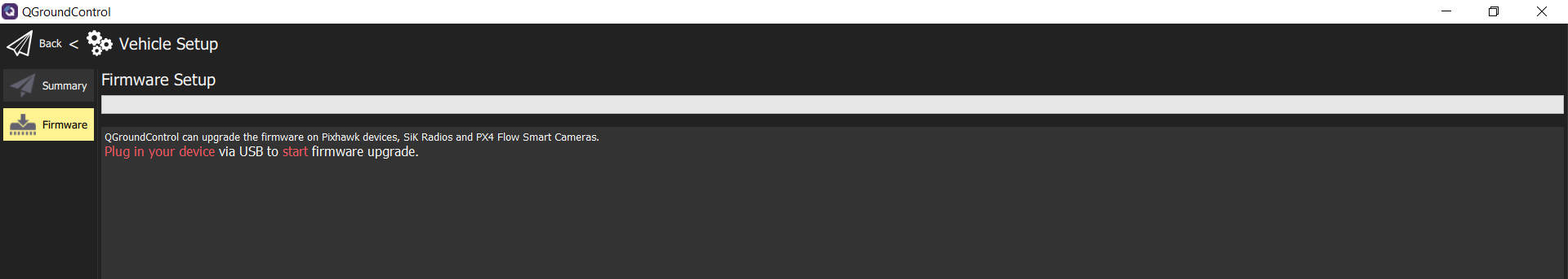
Firmware upload screen in QGC
Note
Make your FC is NOT plugged in when accessing the firmware setup screen.
First access the firmware screen and THEN plug in your FC.
It will recognize the connection and initiate the process.
QGC will ask you to plug in your FC using a USB cable.
A popup will appear that asks you which firmware you want to use.
select “Advanced Settings”, then “Custom firmware file…”
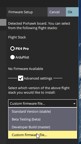
Loading PX4 Pro Stable Release onto FC
Then click “Ok” and select the firmware file you downloaded.
Now, you will see a progress bar. This process should take no more than 2-3 minutes.
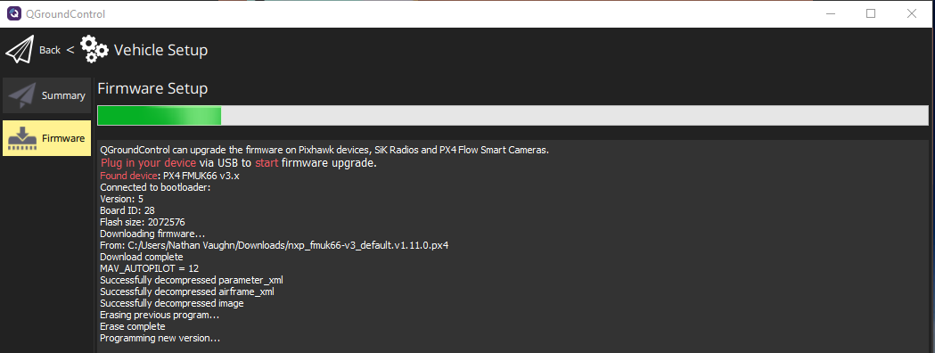
After the PX4 firmware is successfully loaded you will be presented with
the default Vehicle Setup screen. It is necessary to go through the
following steps to ensure a reliable and stable first flight.
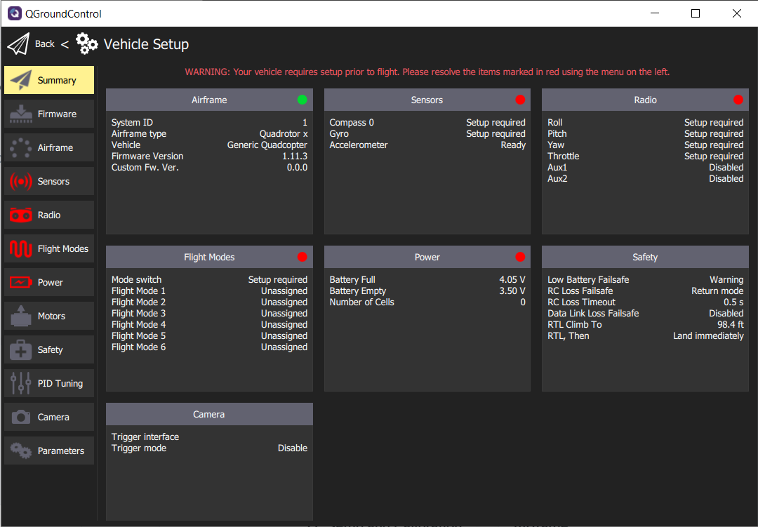
QGC Vehicle Setup screen right after PX4 firmware load
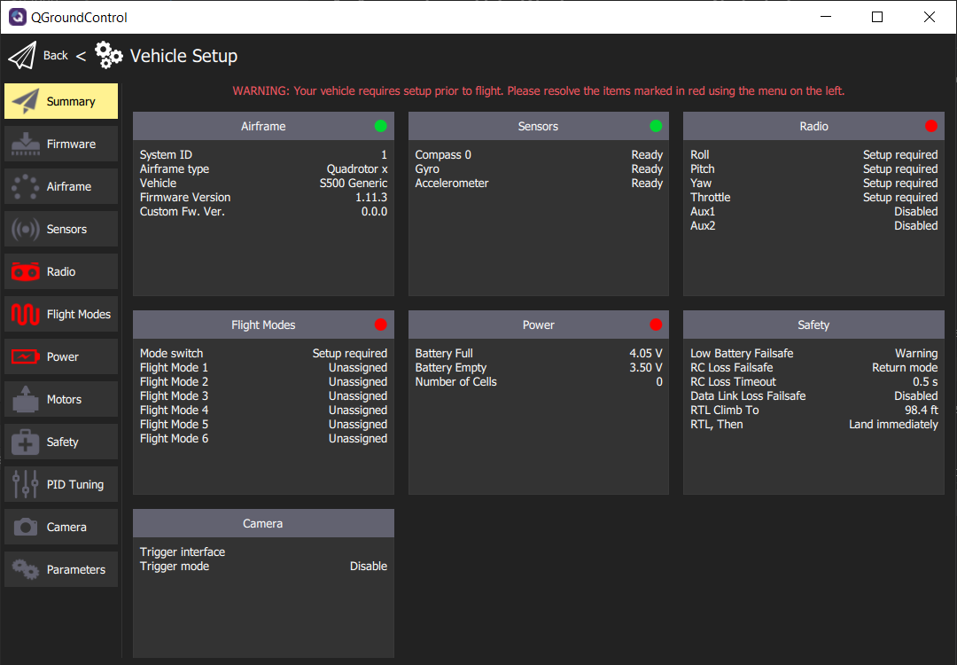
7.2 - Airframe
The AVR drone is 500mm in size and is represented by the diagonal
distance between motors. If you were to measure the distance it would be
close to 500mm. In QGC you will now configure the drone frame, which will
provide optimal settings for flight. Select Airframe in the navigation menu.
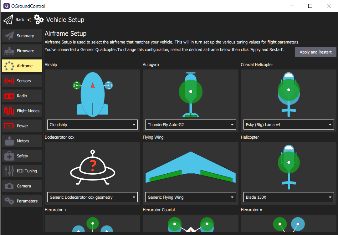
Airframe Setup screen
Scroll down in the Airframe Setup screen and look for Quadrotor x.
Click on the dropdown menu and select S500 Generic as the airframe type.
Scroll back up and click the Apply and Restart button in the top right of QGC.
You will be asked to confirm that you want to restart.
Click Apply and the airframe setting will be saved.
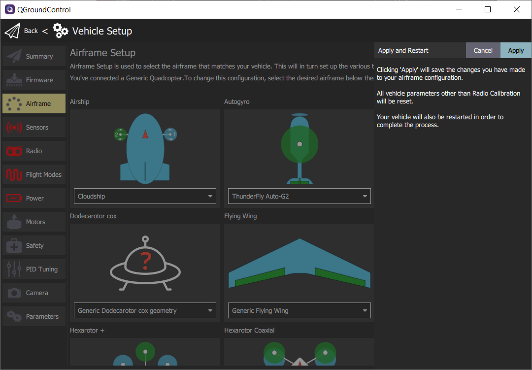
While the FC is rebooting QGC will disconnect for a few
moments and then automatically reconnect.
7.3 - Sensors
The Sensors screen lists most of the sensors that are available to
the FC (internal or external). It allows you to start the calibration process
for the listed sensors. This step is very important for stable flights.
It is required to do the calibration at least once and should be repeated whenever
adding new components to the AVR drone or if flight becomes less stable.
Note
Given advanced assembly of your drone will require additional autonomy components
and peripherals, it is a good practice to understand the calibration process in detail.
Click on Sensors in the navigation menu and let’s walk
through the calibration process for each sensor.
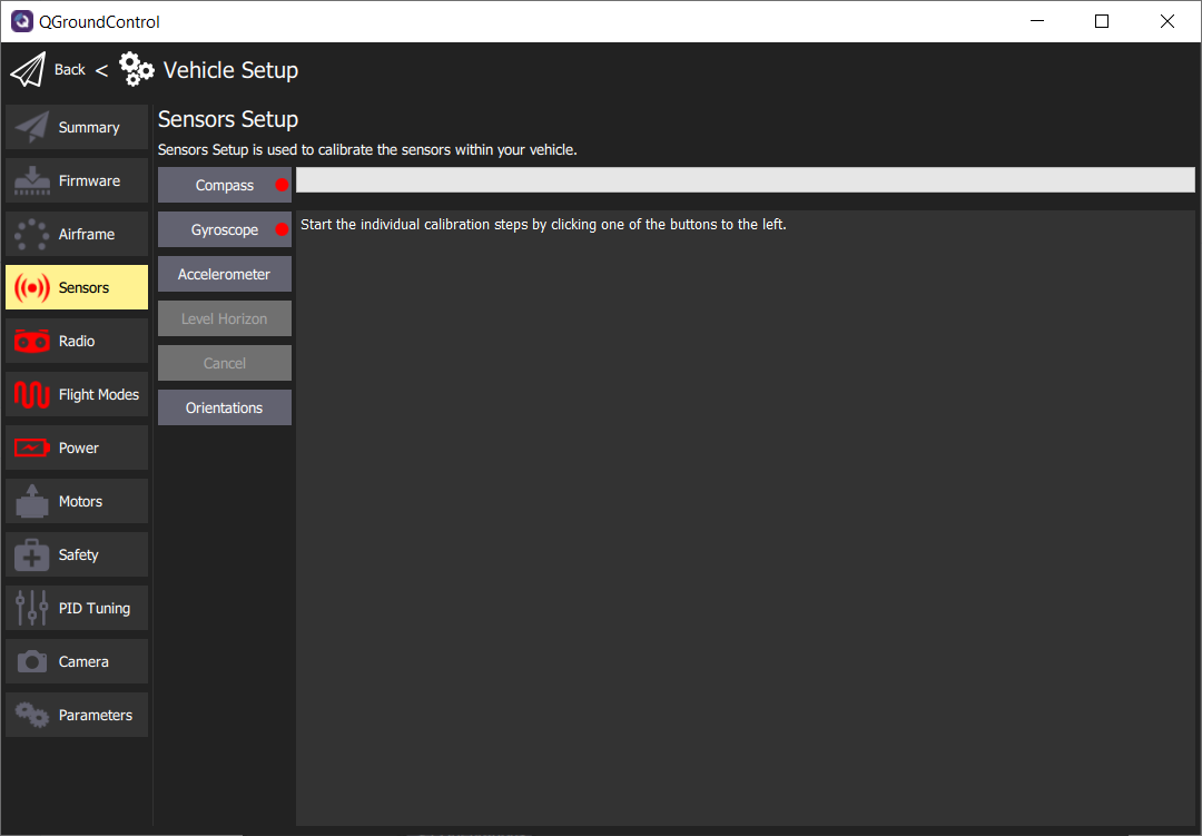
Default Sensors screen
Compass
The compass is important for your AVR drone to maintain proper orientation.
Click on the Compass button and you will be asked to begin the calibration process.
This process requires you to position the AVR drone in a number of set orientations
and rotate the vehicle about the specified axis.
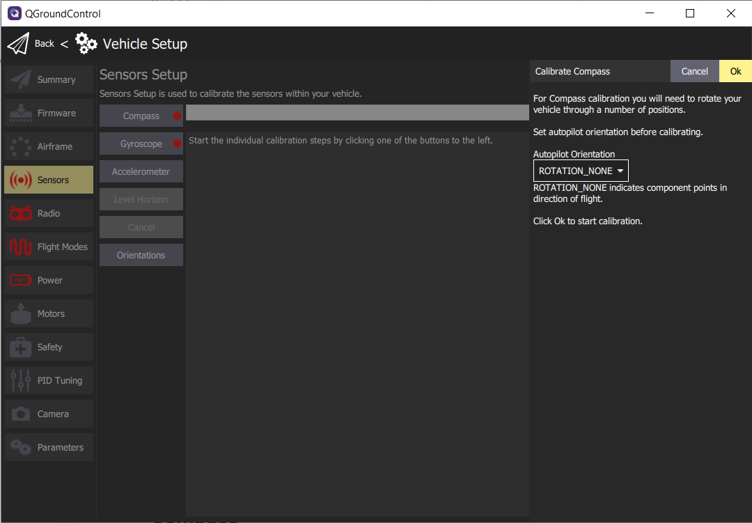
Default compass sensor screen before calibration begins.
Click Ok to proceed with the compass calibration.
QGC will automatically recognize the orientation of the AVR drone and
provide a yellow highlight as shown in the image below.
Note
Don’t be thrown off by the images of an airplane in the QGC
compass calibration process. This still applies to the AVR drone.
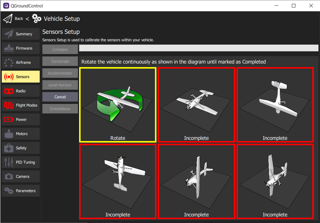
Begin the process of rotating the AVR drone around the highlighted axis.
Tip
You may find it difficult to rotate the AVR drone with USB connected.
It is helpful to have someone keep the cable out of the way while another
rotates the drone around its designated axis.
Once the orientation is highlighted you can begin rotating the drone until the
box is highlighted green. This generally requires one 360 degree rotation
around the axis. The image below shows three of the six orientations completed.
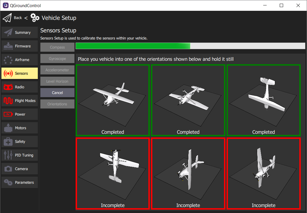
Compass calibration in progress
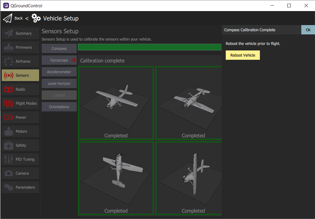
After completing the calibration of all axes click Ok to return to the sensor setup.
It is important to reboot your FC prior to flight,
but for now we will move on to calibrating the Gyroscope.
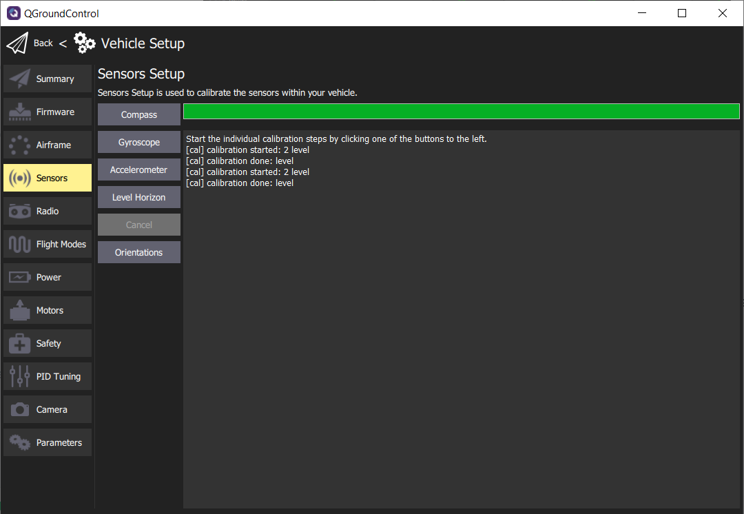
Gyroscope
The gyroscope is an important sensor that will be used to keep your
AVR drone level when hovering. Now that the compass calibration is complete
you will click on Gyroscope to being the process. This will be much easier
than compass calibration! Make sure your AVR drone is on a level surface
and click Ok.
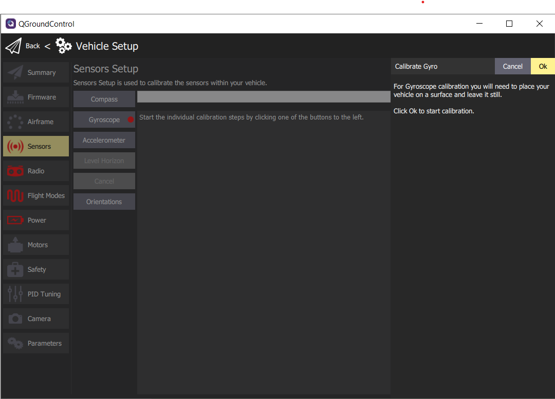
After a few seconds, the gyroscope calibration will be complete.
Successful gyroscope calibration
Accelerometer
The accelerometer works in conjunction with the gyroscope to keep your
AVR drone level along each axis. Click on Accelerometer and then
Ok to begin the calibration process.
This process is fairly similar to compass calibration but does
not require you to rotate the drone around each axis. You simply
need to hold the drone level in each orientation. QGC will detect
the orientation, which is denoted by the yellow border.
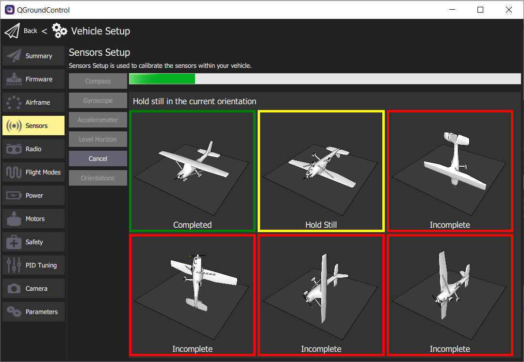
Accelerometer calibration in progress
Hold your AVR drone steady in each orientation for approximately 5-10 seconds.
As you complete each axis the border will turn green in QGC.
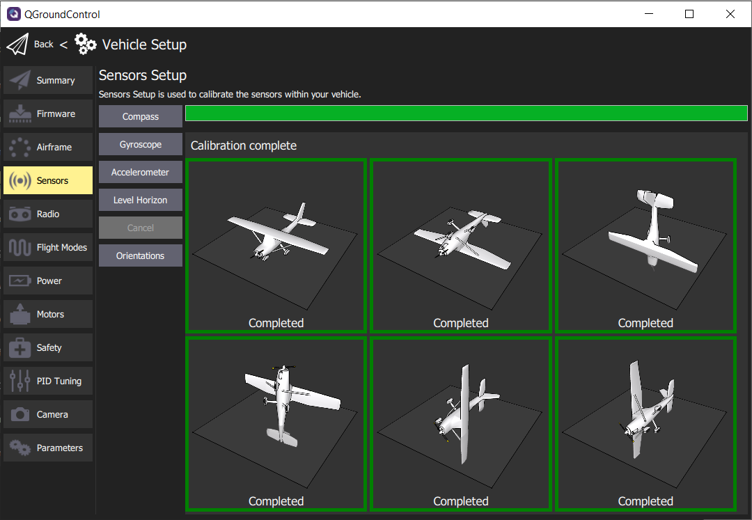
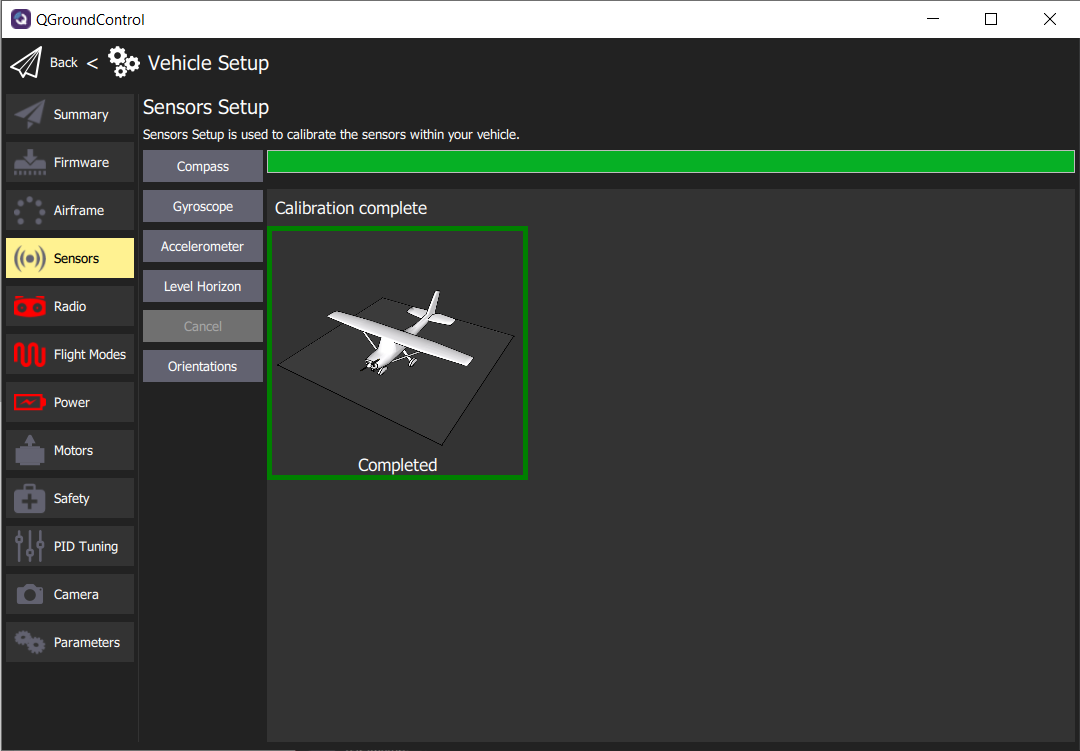
Accelerometer calibration complete
Level Horizon
Level horizon is a simple calibration to make sure your FC understands the
default level position when powered on. Click on the Level Horizon button and
then Ok. This process will take more than a couple of seconds to complete.
Level Horizon calibration complete
Orientations
Given we have mounted the FC in its default orientation
(facing up and forward) this calibration is unnecessary.
Nice work! You have calibrated the necessary sensors for your AVR drone
to be able to know its orientation and keep level during flight.
The following Summary screen shows the successful steps completed in green.
Now we will move onto setting up the Radio (aka Transmitter).
Summary screen showing all sensors calibrated and ready for flight
7.4 - Radio
In the RC Transmitter Setup
section we configured the stick and switch channels.
Now we will calibrate the endpoints of these channels so they can be saved to the FC.
QGC makes this very easy to do and the process can be observed in the following video.
Now that your transmitter has been calibrated using the Radio screen in QGC
we will move onto setting up our flight modes.
7.5 - Flight Modes, Arming, and Kill Switch
The primary goal of the basic assembly is to be able to pilot the AVR drone in stabilized mode.
Therefore we will configure SWB (3 position switch) to control which flight
mode we’re in. In addition to setting up flight modes, we will also enable a kill
switch on SWD (2 position switch). This is VERY IMPORTANT in case the
AVR drone needs to be shut down due to a fly-away or complete loss of control.
The video below demonstrates this process.
7.6 - Power
Power Setup
For correct display of battery percentage, you should always specify the
correct number of cells in the battery. In our case this will be 4 since we
are using a 4 cell LiPo battery. You should also calculate the value for
the voltage divider to calibrate the voltage readings coming from the power
module. This can be done by measuring the overall voltage with the Venom cell checker.
Then you can input the measured voltage into the Calculate Voltage Divider prompt.
These settings will provide you with an accurate battery percentage while the drone
is idle on the ground, so you can determine whether it is still safe to take off
and when you need to land. PX4 also has a fail-safe that prevents arming when the
battery percentage is too low. The video below walks through the power setup.
ESC Calibration
To ensure that all motors correctly respond to commands coming from the FC,
you should perform an ESC “calibration”. It makes sure that the ESCs are aware of
the minimum and maximum pulse-width modulation (PWM) values that the FC provides.
This can be done by pressing the ESC calibration button and following
the on-screen prompts. The calibration process requires a USB connection since it
involves steps where you have to disconnect and reconnect the battery.
The video below covers this in detail.
7.7 - Safety
Safety Setup
Previously, in the RC Transmitter Setup section, we covered
Setting Up Failsafe.
In QGC we need to make sure we disable some of the failsafe options, as many of
them are related to GPS-enabled drones. AVR is all about indoor navigation in a
GPS-denied environment therefore it warrants a different safety configuration.
The video below walks through the setup process.
7.8 - Motor Test
One physical check that must be done to ensure your AVR drone hovers properly
is to verify that the motor positions and rotations are correct. We previously covered ESC wiring which should ensure that the FC output is going to the right motor.
We discussed motor rotation when installing the frame arms and learned that the rotation for each motor is important. You may recall the
image below and we will refer to it one more time before we run the motor test.
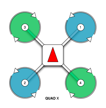
Motor position and rotation diagram
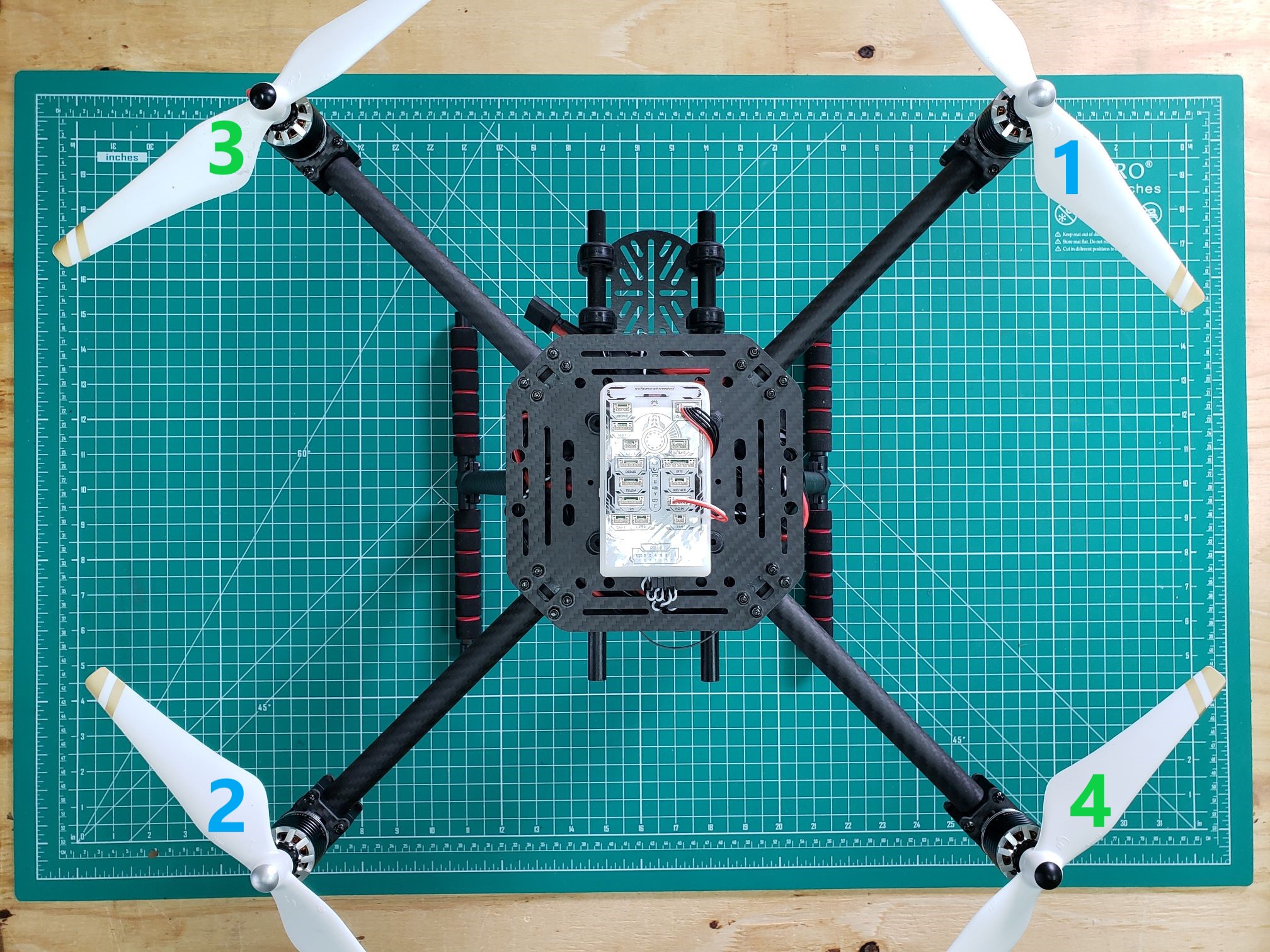
Motor positions and propellers installed with the nose of the AVR drone pointed forward
The video below will walk through the necessary steps to run the
position and rotation test.
Tip
It is not necessary to do this motor test every time you fly,
but it is highly recommended if any wiring modifications have been
made to your AVR drone.
8 - Checkpoint 1: Initial Flight Test
8.1 - Before You Fly
Much of the work done so far has created the foundation for your AVR drone.
The following videos will talk through the process you should follow each
time you fly. These are important checks to make sure your AVR drone operates
correctly and keeps all team members safe.
Pre-flight Checks
Installing Propellers
Place your AVR drone in its desired takeoff location and install the
propellers as demonstrated in the video below.
8.2 - Flight Test
Let’s Fly!
We have covered a tremendous amount of information to get to this phase
of the competition. Now it’s time for our first flight test! Watch the video
below to understand the basics of getting your AVR drone in the air and how
to control it.
8.3 - After You Fly
As discussed in the Flight Test
video always be sure to power down your AVR drone and run a voltage
check on your battery. Always refer back to the
battery documentation
if you have any questions regarding
charging, maintaining, and storing your battery.
Congrats on
building your AVR drone,
configuring it,
and performing your first flight test!
We know it has been a challenging and hopefully rewarding journey,
and there will be a lot more exciting things planned as you work towards
the competition.
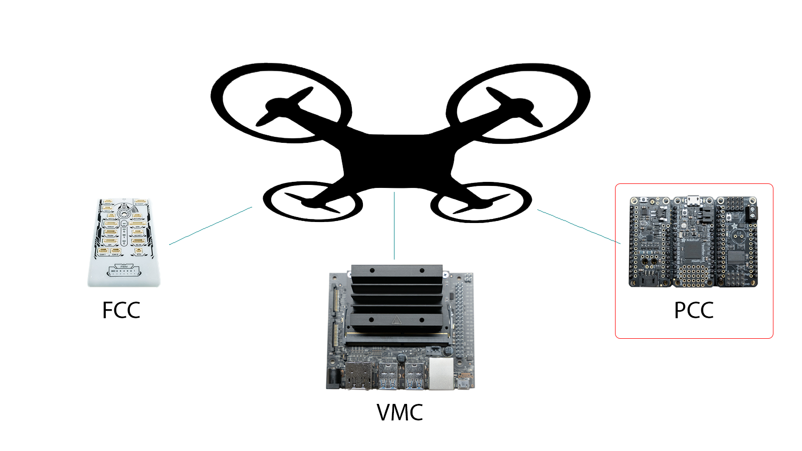
9 - Peripheral Control Computer (PCC)
This guide covers the steps for assembling the Peripheral Control Computer, which will control LEDs and servos.
9.1 - Physical Assembly
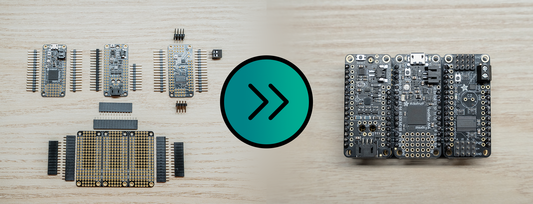
Assembling the Peripheral Control Computer is fairly easy,
and just requires a bit of soldering.
- Soldering Iron (I used an iron at 450C, but the recommended solder melts around 200C)
- Soldering Iron Tip Cleaner
- Solder (Recommend 60/40 Tin/Lead)
- Wire Strippers
- Breadboard
PCC Parts - Box 5
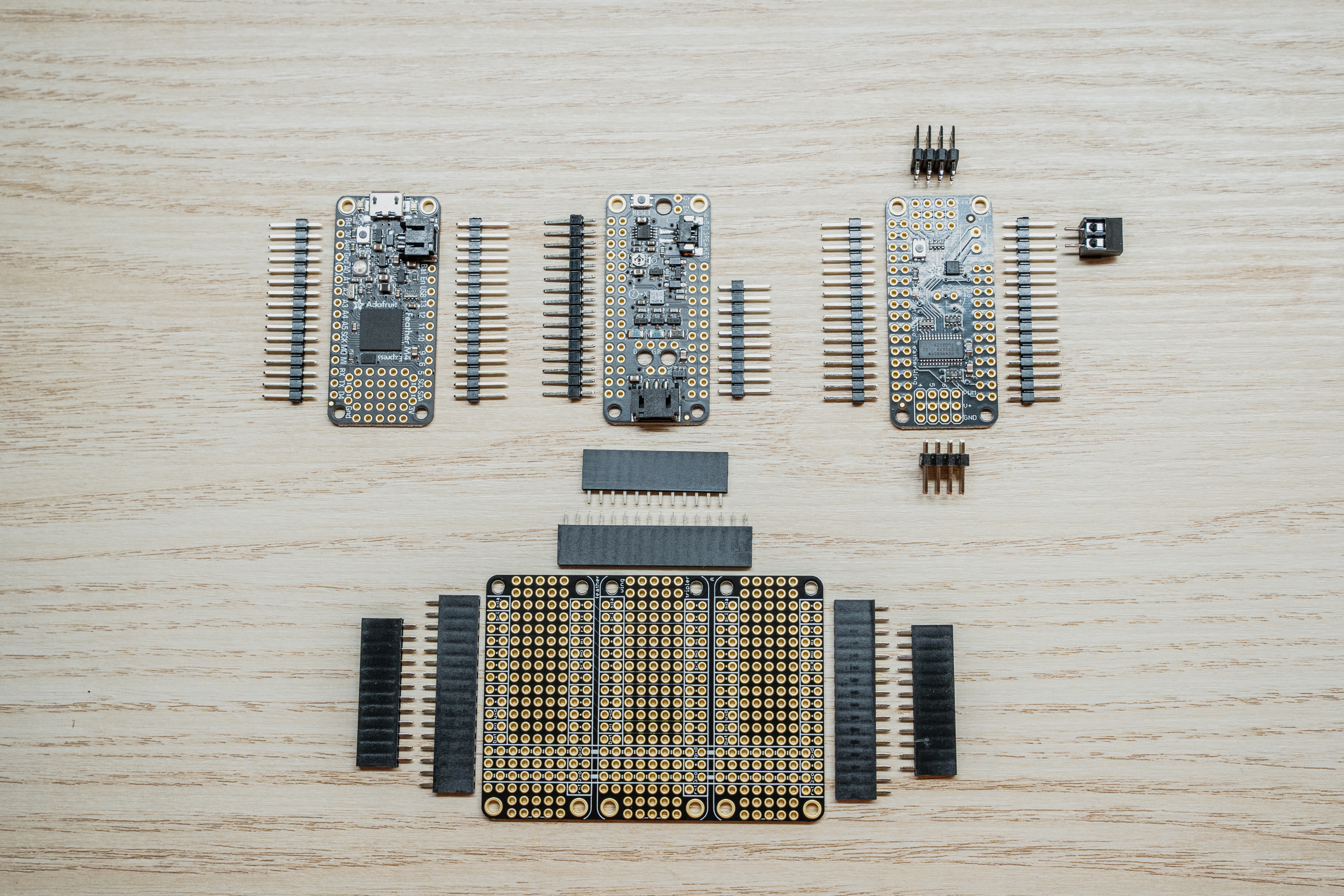
Before we get started, let’s make sure we have all the necessary parts for the PCC.
The PCC ships in 4 plastic bags consisting of the following:
- 1 x Adafruit Feather M4 Express (Pictured upper left)
- 2 x 16x1 Male Pin Headers
- 1 x Adafruit Prop Maker Featherwing (Pictured upper middle)
- 2 x 16x1 Male Pin Headers
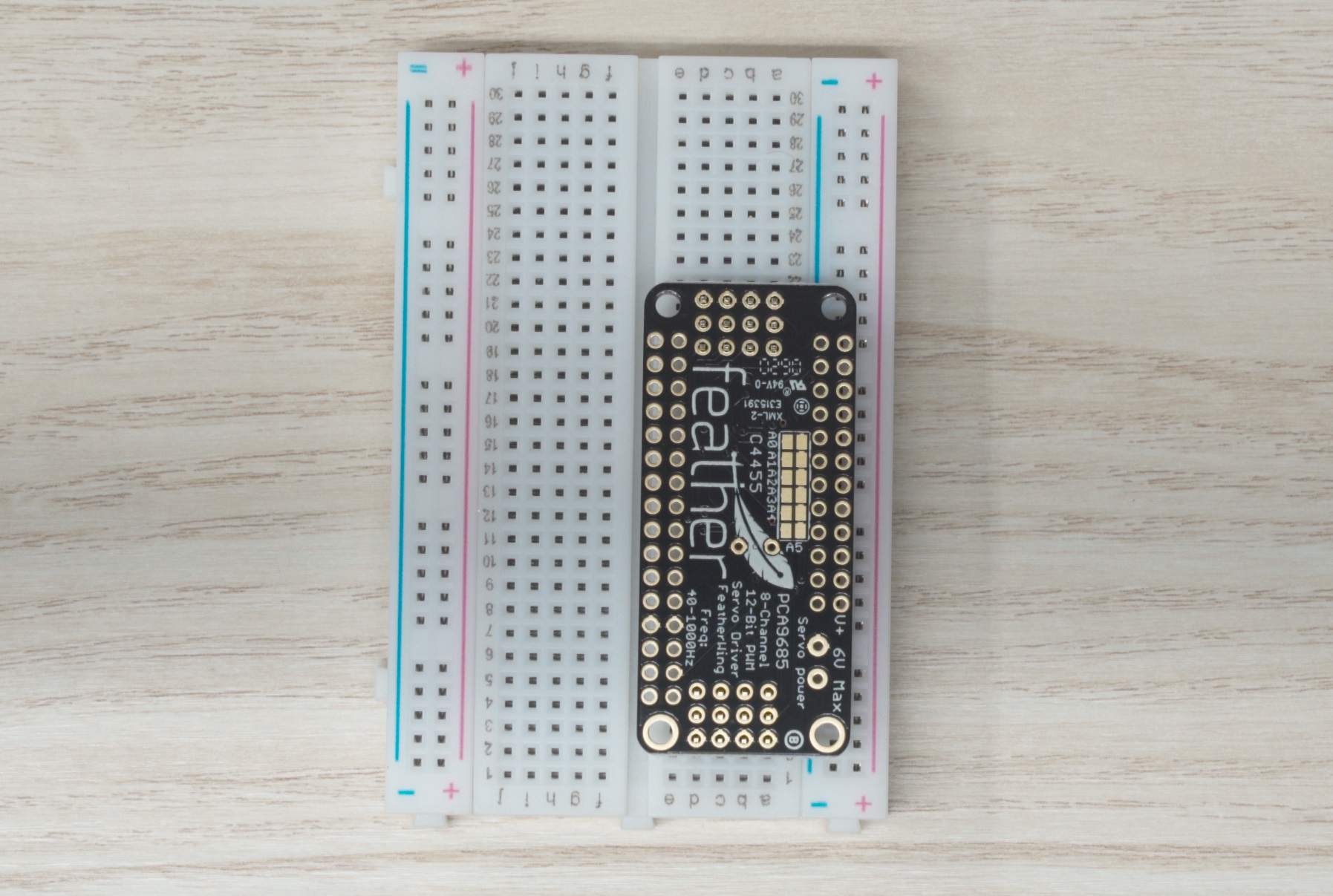
- 1 x Adafruit Servo/PWM Featherwing (Pictured upper right)
- 2 x 16x1 Male Pin Headers
- 2 x 4x3 Male Pin Headers
- 1 x 2 screw-terminal thru-hole adapter
- 1 x Adafruit Featherwing Tripler (Pictured Bottom)
- 3 x 12x1 Female Pin Headers
- 3 x 16x1 Female Pin Headers
Note
The picture only has a 9 pin header for the Prop Maker, because mine broke
off in shipping. Don’t worry this isn’t an issue, just place them
together when it’s time to solder.
Solder the Feather M4 Express
Before we dive in, let’s go over a couple of warnings and tips.
Warning
Soldering irons get hot… like really really hot.
Pay attention to finger placement, and don’t burn yourself.
Tip
The key to an enjoyable soldering experience is patience, a clean tip, and a hot iron.
Step 1: Assemble Feather M4 Express
The Feather M4 is the brains of the PCC. It receives commands from the VMC and
executes them in order to change the color of the LEDs or move a servo.
You’ll see that the M4 Express has 16 pins along its left side
(assuming the micro USB port is the top), and 12 pins along the right side.
Because the M4 Express ships with 2 x 16x1 headers, we need to cut one side down.
You should be able to use scissors to trim one of the headers to 11 pins. Why 11?
The PCC doesn’t make use of the “Bat” pin and in our testing including this pin
caused issues. For this reason, we chose to omit this pin.
You can see it is missing if you expand the picture below:
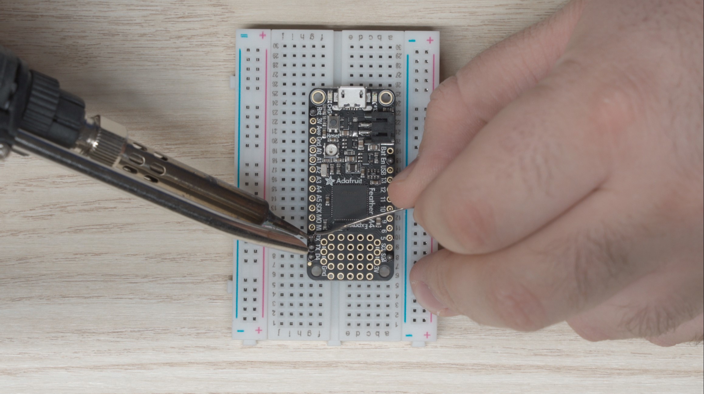
M4 Express being soldered
Tip
Place the headers in the breadboard, long side down to act
as a fixture for soldering. It will be much easier this way.
With the headers cut to length, grab your breadboard and place the headers in
the “a” and “g” column as in the picture above, with the long side of the headers
going into the breadboard. Make sure it’s lined up correctly and set the M4 Express
onto the pins. The feather should not move around anymore and you can begin soldering.
For the smoothest outcome, start by soldering the pins in the four corners so the pins
don’t move around on you when soldering the rest. I like to use a hot
iron (around 450°C) with a fine tip for this.
Use the following steps to complete a solder joint:
- Place the iron tip on the feather such that it is making contact with the
protruding pin as well as the donut-shaped pad that the pin protrudes through.
- If your iron is clean and hot, after about 5 seconds you should be able to move
your solder in to touch the iron at the junction where the iron and the pin meet.
The solder should melt almost immediately, and wick around the pin.
- Don’t go overboard with the solder. You want just enough that the solder forms a
cone shape around the pin. Less really is more here.
- Pull the solder and iron away from the board and inspect your work.
- Repeat steps 1 through 4 for each pin on the M4 Express.
Once complete you should have solder joints that look like this:
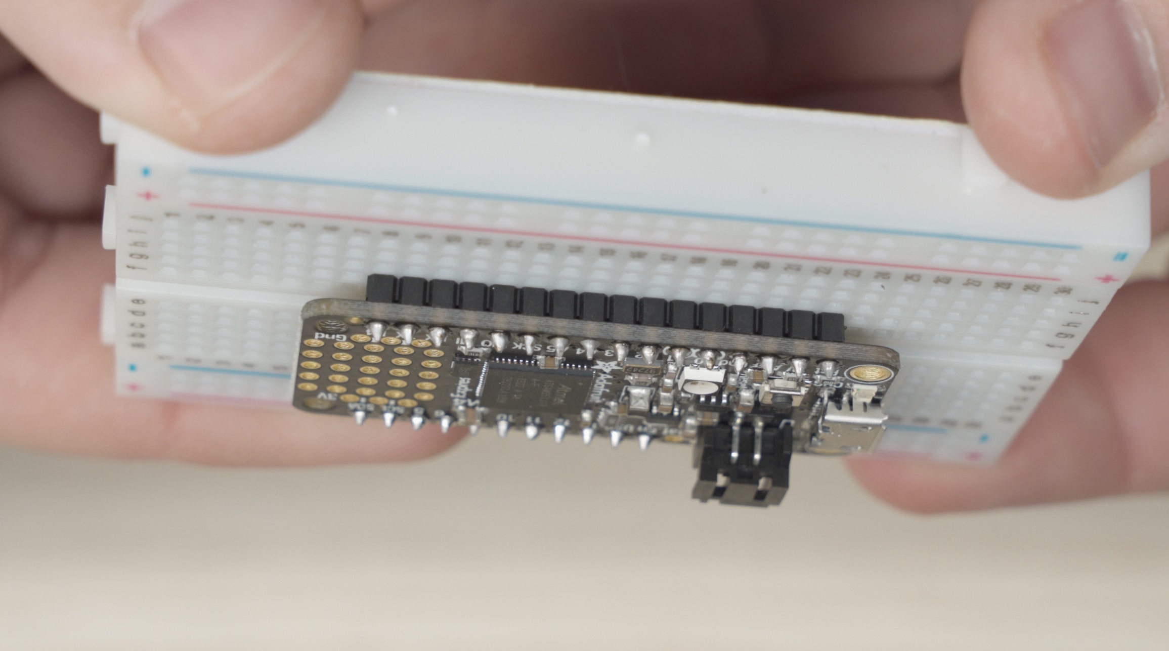
Completed M4 Express
Once you’re happy with your soldering work, grab each end
(the micro-usb and opposite side) and slowly inch the feather out
of the breadboard. It is very easy to bend a pin trying to remove
it so just go slow and be careful.
Tip
If you bend a pin removing the soldered part from the breadboard,
use some needle nose pliers to bend it back straight.
Don’t work the pin too much though, or you’ll break it.
Hopefully that wasn’t too bad! Now we need to repeat similar steps for
the prop maker and the servo featherwing.
Solder the Prop Maker
The steps for the Prop Maker are the same as the M4 Express.
Make sure to cut one set of male headers down to 11 pins and skip the “Bat” pinhole.
Place the headers into the breadboard and solder all the pins.
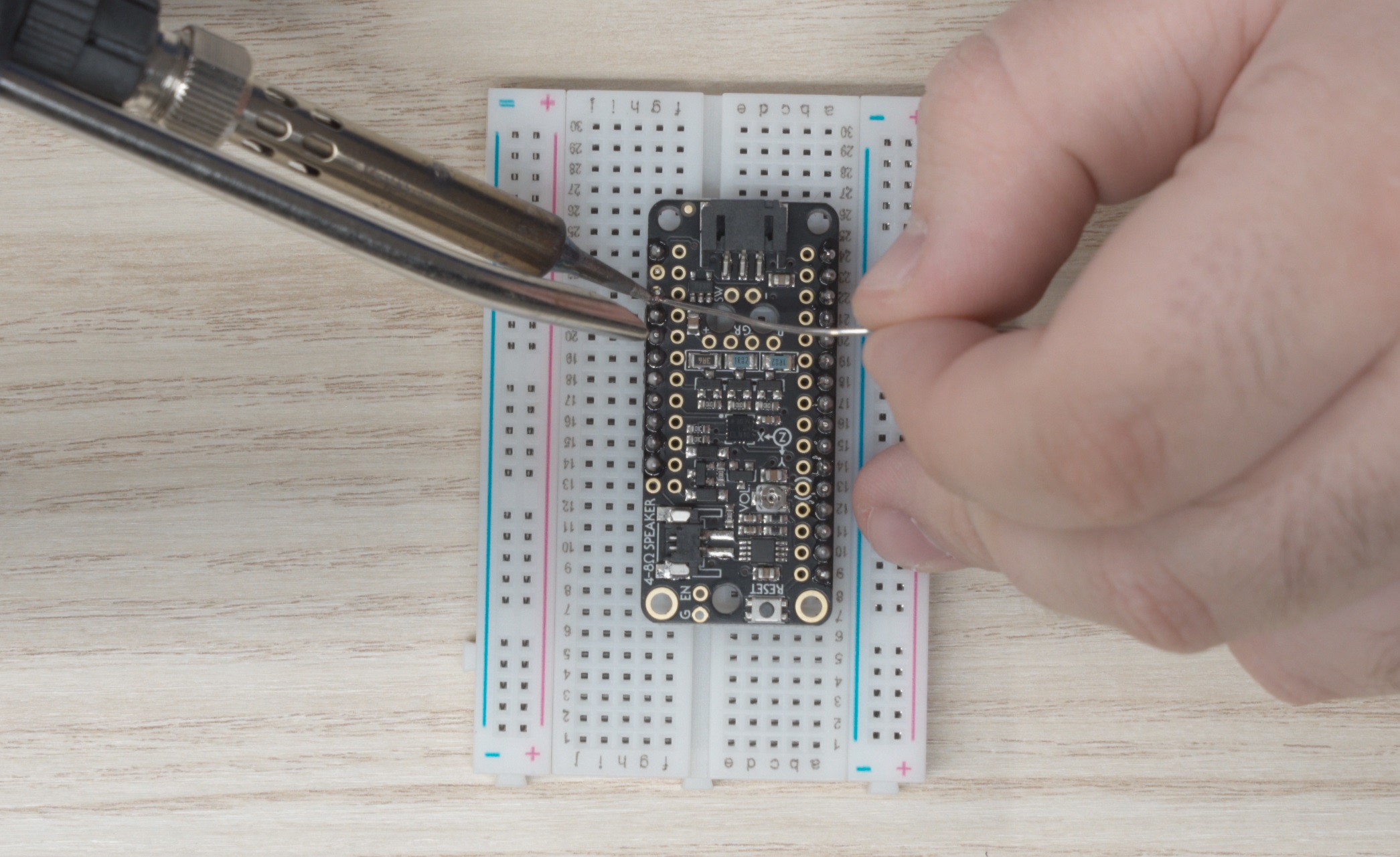
Prop Maker being soldered
Solder the Servo/PWM Featherwing
For the Servo featherwing its easiest if you solder the 4x3 headers first:
- Place one of the headers into the breadboard first.
- Place the other set short-end first into the top of the featherwing.
- Flip the featherwing upside down and onto the headers already inserted
in the breadboard.
- Solder these pins
Servo Featherwing placed upside down on the 4x2 headers
Once the 4x3 headers are soldered in place, remove the featherwing from the
breadboard and solder the 16x1 headers, while remembering to trim the short
side to 11 pins.
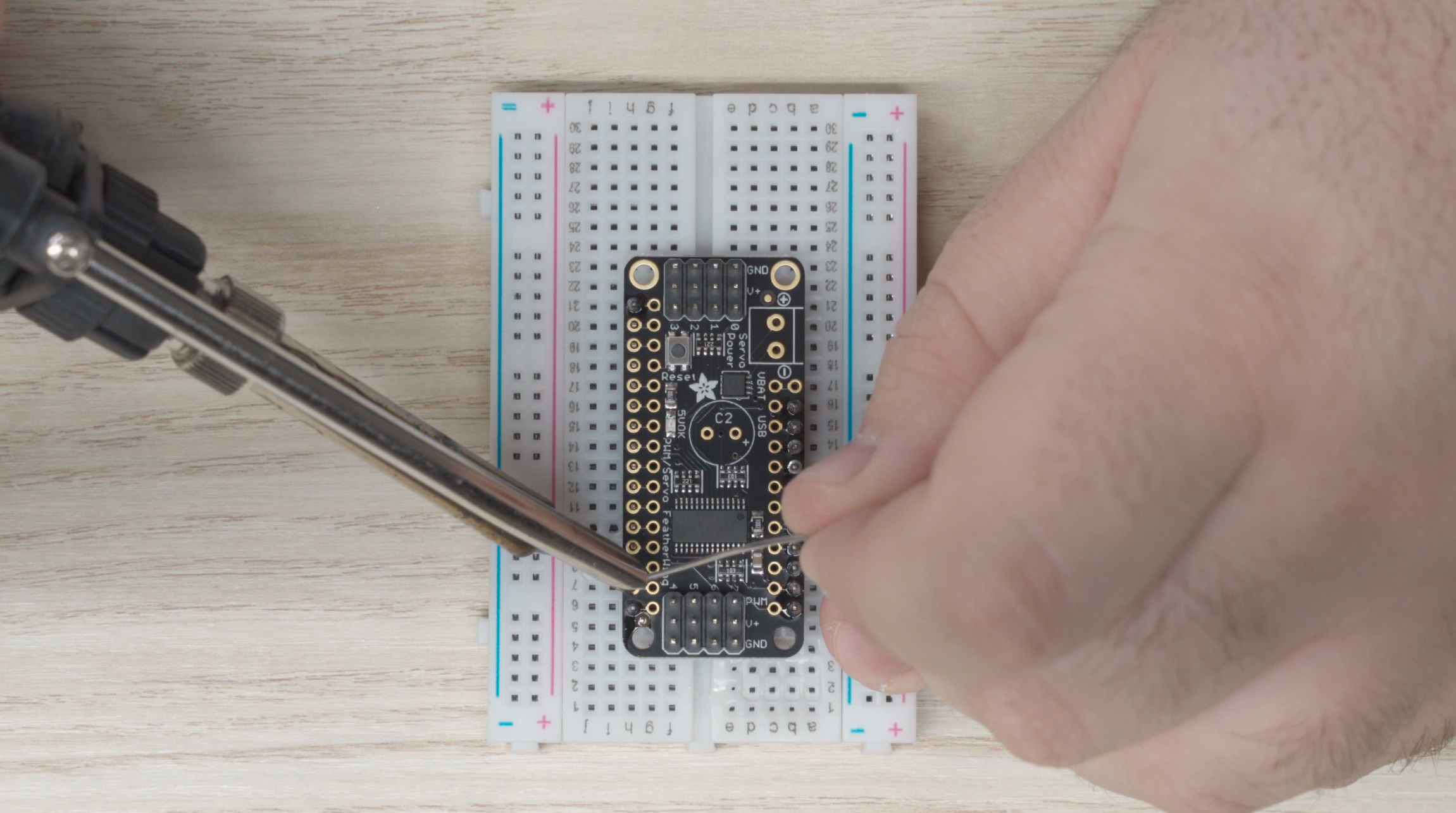
Servo Featherwing being soldered
Finally, we need to install the screw terminal:
- Remove the Featherwing from the breadboard.
- Place the screw terminal in the top of the circuit board with the
terminals facing outward
- Turn the assembly upside down and place it on top of the breadboard.
- Solder the screw terminal on.
Installing the USB Power Jumper
In order to run the PCC from a laptop for testing,
we’ll have to make a USB power jumper to connect the USB power
from your laptop to the servo power rails. In the future,
once the PCC makes its way onto the drone, the servos will have
a dedicated power supply.
First, we need to install a pin for the wire to connect to:
- Find a spare male pin from the headers we used in the above steps
- Place the pin into the area labeled “USB” on the servo featherwing
(highlighted below)
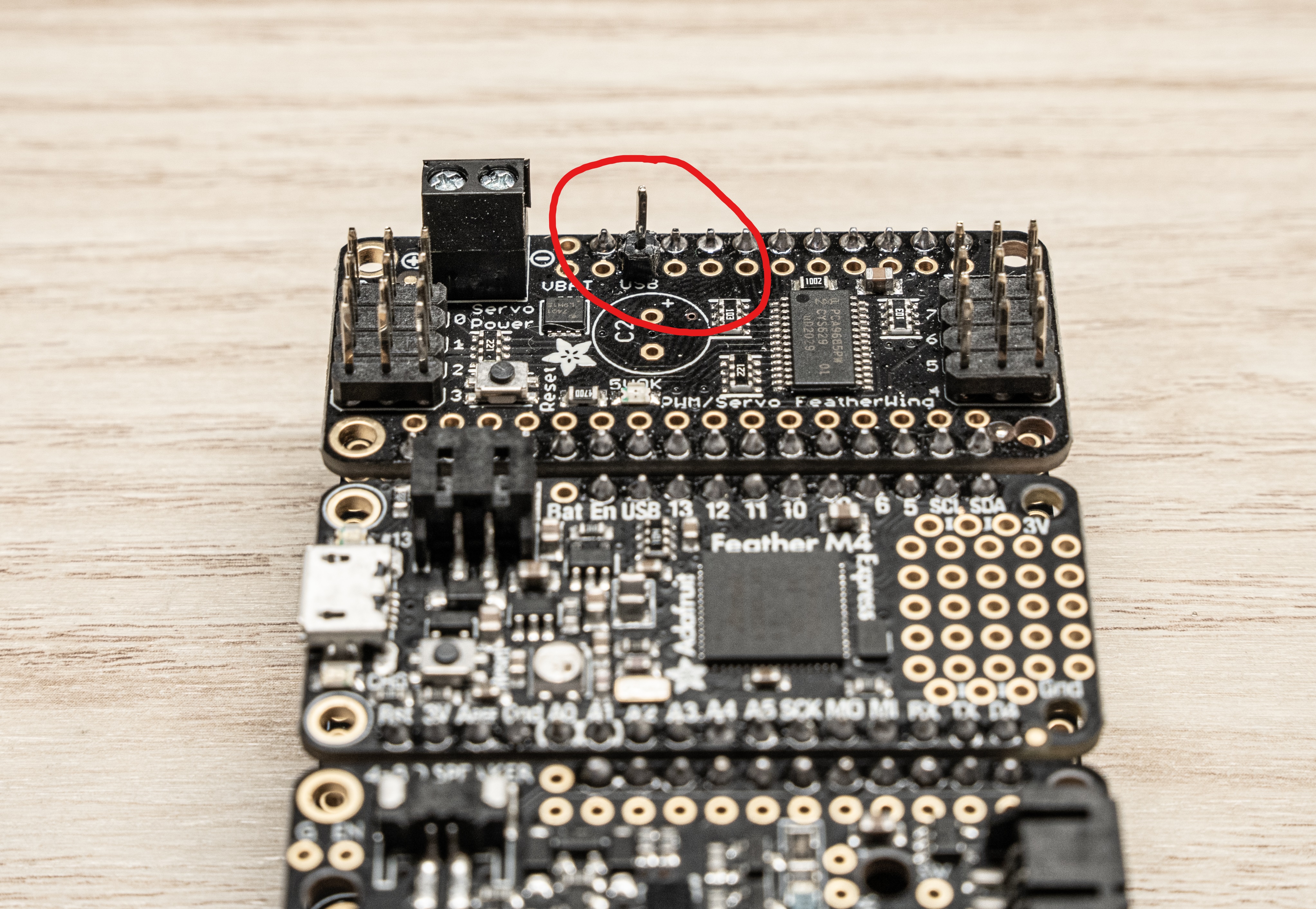
- Solder the pin from the underside
Now we need to make the jumper wire. Take a spare wire from the kit
(there should be a whole bag with the proper connectors already on them)
and cut it down to just about an inch. Then strip about 5mm from the end
like shown below:
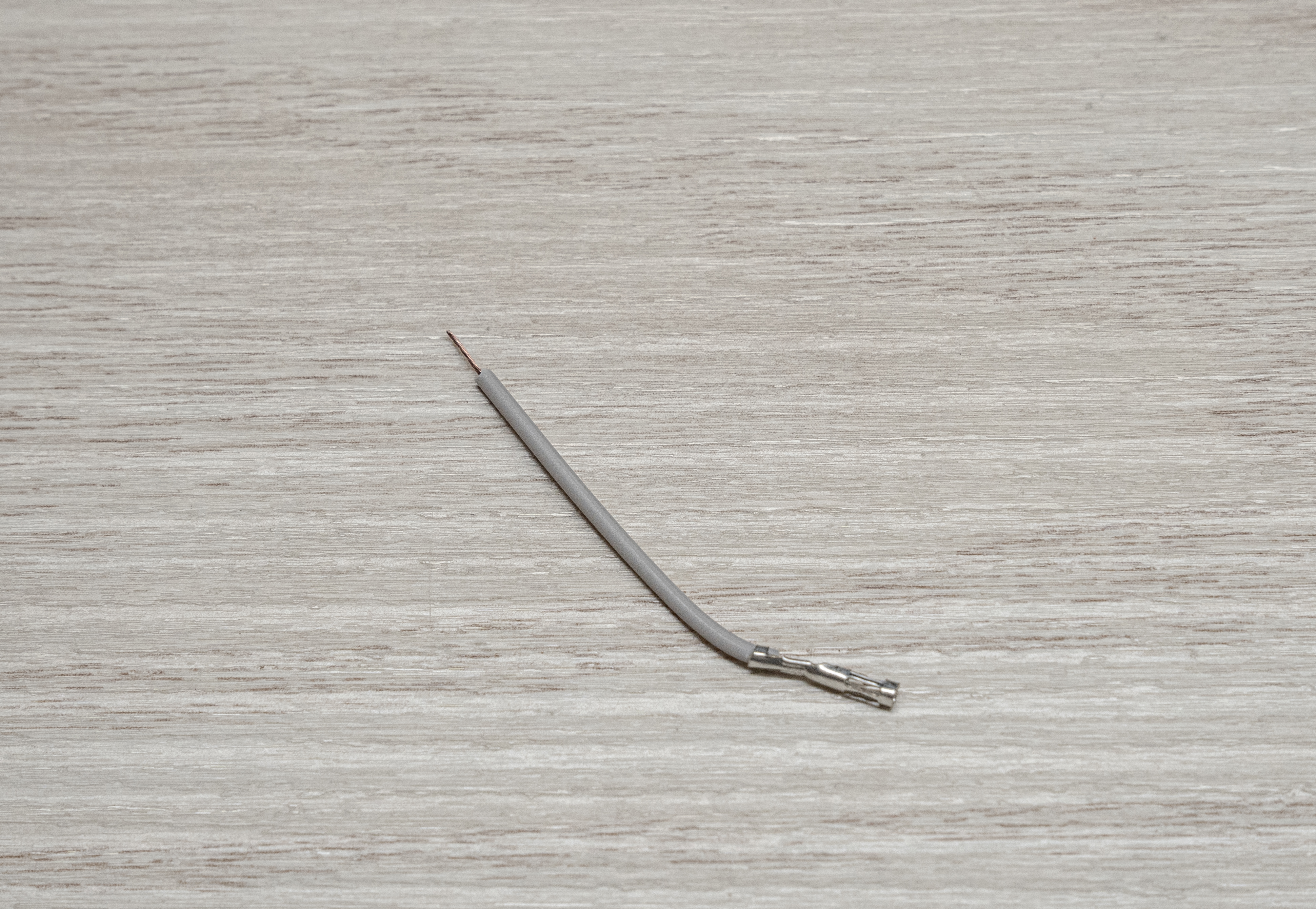
Finally, place the terminated end on the pin we just soldered,
and the bare end into the + side of the terminal block and screw it down.
That’s it! The Servo Featherwing is now complete.
Solder the Featherwing Tripler
The tripler can be the trickiest piece to solder if you don’t follow this simple trick:
Hold the tripler circuit board with the silkscreen print facing upwards.
Drop the headers into the board as shown in the picture below:
Warning
It’s crucial that you place the headers in the orientation shown below!
You should drop the headers into the board with the silkscreen facing up.
Failure to catch this before soldering will mean that you’ll likely have to
purchase another Tripler, as these parts are hard to desolder.
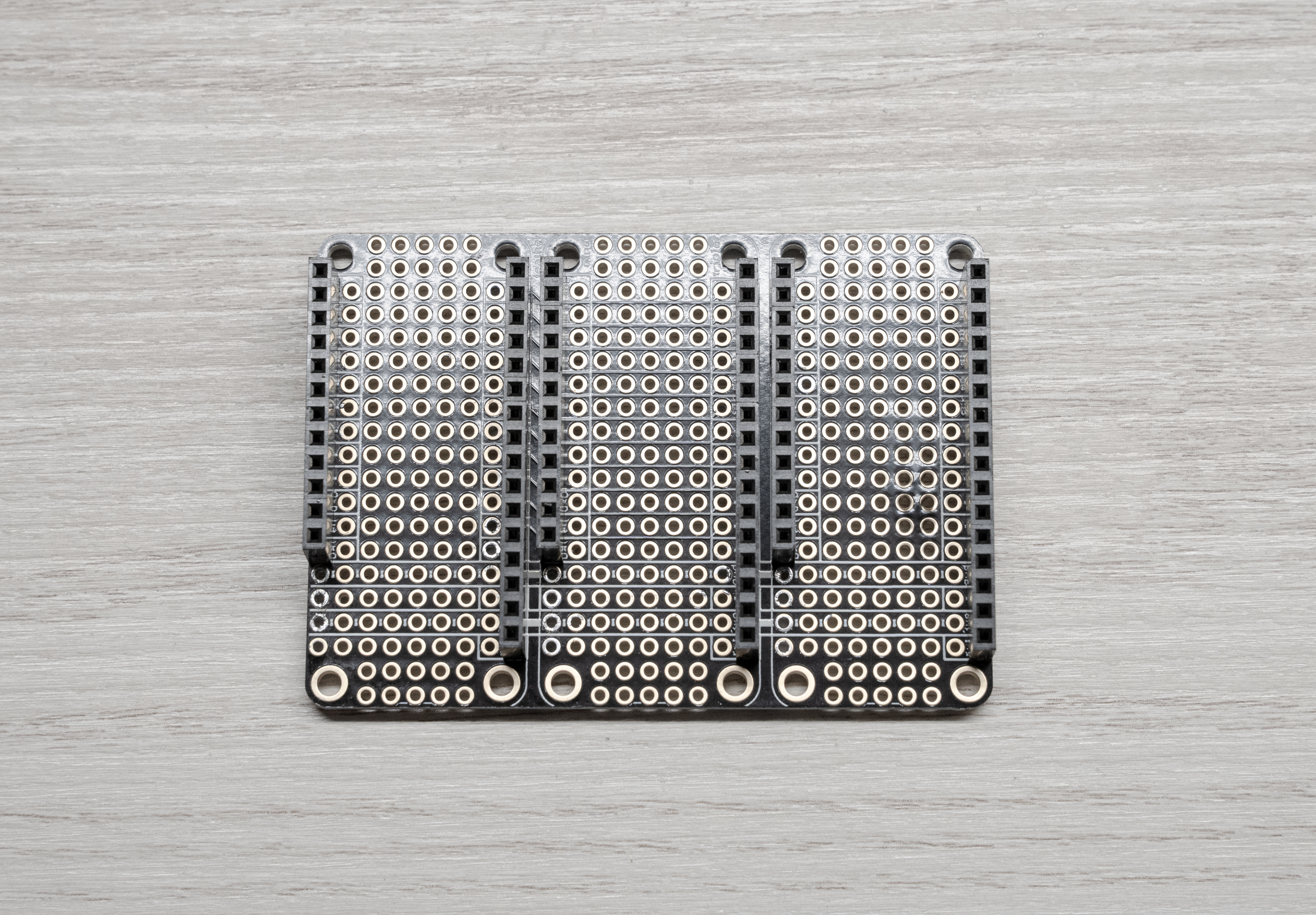
Then turn the whole thing over on its back (being careful not to drop the headers)
and then solder each pin from here.
Tip
It’s easiest if you “tack” one pin from each row of headers and then tweak
your alignment before doing the rest.
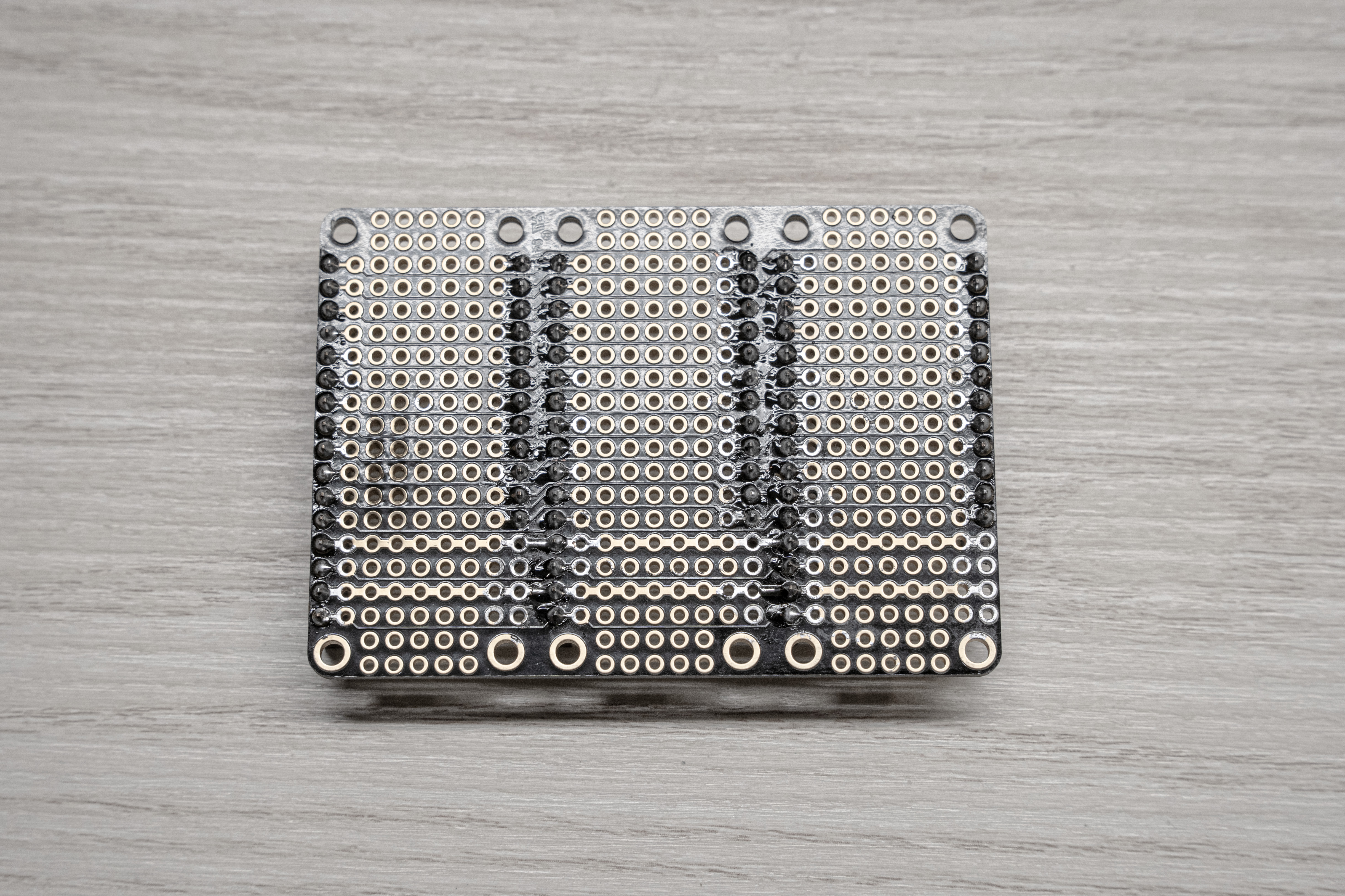
Back of soldered tripler for reference
Adding the Laser Trigger
For the 2022 season, we are making use of a laser pointer. In order to be able to
trigger the laser from the PCC we need to add some extra pins connected to GND and A4
on the express to the Tripler.
Start by placing the Tripler down, and lining up the M4 Express with the headers on the
Tripler like shown below:
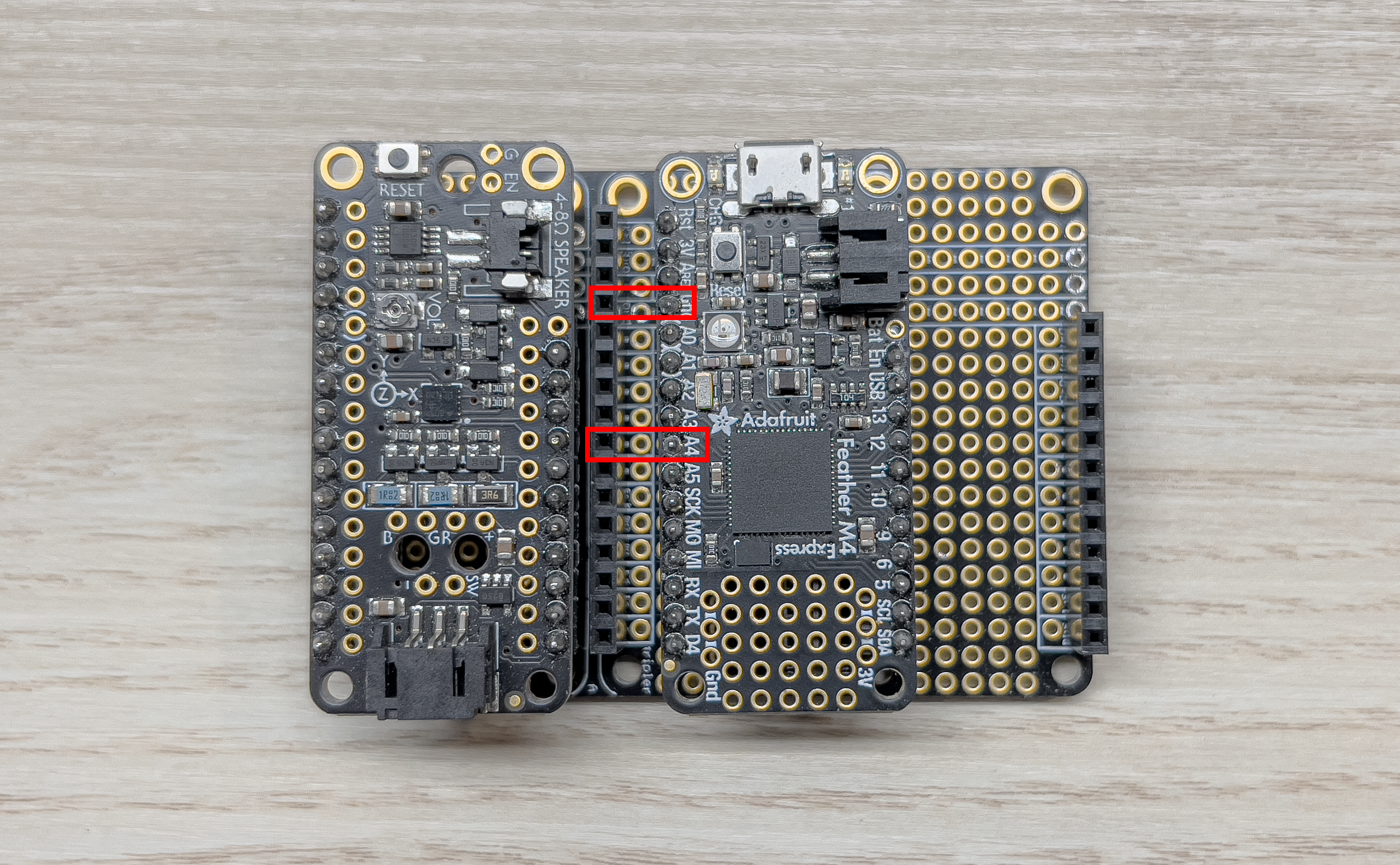
Tripler
I used a spare male dupont-connector wire to mark the pins of interest by plugging them
into the desired spots on the header.
Next, grab some of the spare header pins and break two single-pins off:
Separated Pin
Place them into the holes on the Tripler right next to the point of interest and use
something flat to place over the board to hold the pins in place while you flip it
over. I used an old PCB but you could use paper, cardboard, etc. Now solder the pins in
place.
You should now have something like this:
Soldered Pins
Now place a female dupont-connector wire on the pins and bend them down to the right.
They should fit perfectly between the header rows like such:
Note
Be sure to use your 12 inch female-to-female jumper wires as these will eventually need
to run from the top mounted PCC to the bottom mounted laser.
Bent Pins
Thats it! Move on to the next step!
Putting It All Together
Now we can just pop the Featherwings into the Tripler as shown below:
Completed PCC
Now your PCC is assembled!
9.2 - Flash the PCC
Setup
To flash your PCC, you need to download and install a tool called BOSSA first.
Windows/MacOS
Go to this page and download and install
the bossa-x64-<version>.msi file for Windows, or the bossa-<version>.dmg file
for MacOS.
Make sure to install the device drivers that it prompts you to install as well.
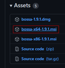
Download this installer file
Run through the setup wizard
Linux
For Linux, you’ll need to compile and run BOSSA from source.
git clone https://github.com/shumatech/BOSSA
sudo apt install build-essential libwxgtk3.0-gtk3-dev libreadline-dev
# if libwxgtk3.0-gtk3-dev cannot be found, run `sudo apt-cache search libwxgt*`
# and install the next closest match
cd BOSSA
make -j
./bin/bossa
Flashing
After getting BOSSA installed, you need to also download the PCC firmware that you’ll
be loading. Go to the
AVR release page
and download the pcc_firmware.<version>.bin file.
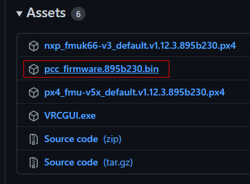
Download this firmware file
Now you’re ready to flash your PCC! Follow the next steps exactly to not
run into any issues.
First, plug your PCC into your computer with the provided MicroUSB cable.
Note
Open Device Manager in Windows, and you should see at least one entry under
“Ports (COM & LPT)” (if this doesn’t happen, that’s okay, it means the firmware isn’t
loaded or corrupted, but we’re about to overwrite it anyways).
Normal PCC COM port
Quickly double-tap the little reset button right next to the MicroUSB connector.
The LED next to the button should briefly flash red before turning solid green.
Note
Additionally, the PCC should also now show up as a USB device in Windows
titled “FEATHERBOOT”, and the COM port you saw before should now be gone and
replaced with one with a different number.

Bootloader PCC COM port
This puts the PCC into bootloader mode so we can flash new firmware.
Open BOSSA and select the COM port that has now shown up from the previous step,
or the serial device ttyACM0. Also select the firmware file you downloaded.
Warning
Forgetting this next step will cause lots of confusing results!
In BOSSA, make sure to put in a flash offset of 0x4000 and select “Erase all”.
BOSSA settings
Now, you can hit the “Write” button!
Flashing complete
You can also optionally click the “Verify” button as well just to make sure
everything flashed correctly.
Verificiation complete
Finally, to get the PCC out of bootloader mode, and make sure the firmware is working
correctly, unplug the PCC and plug it back in, or press the reset button once.
The bright green LED should remain off and the original COM port should show
back up in device manager.
Success
You’re now ready to test it out!
9.3 - Test the PCC
Physical Setup
On your PCC, we’ll need to make use of a USB power jumper to
power the servos from our laptop.
Installed USB power jumper
Warning
MAKE SURE to ONLY use the jumper when testing with your laptop.
NEVER use the USB power jumper when the PCC is connected to the Jetson.
This is because the servos may draw enough current in certain scenarios
that would cause the current protection to trip on the power supply and
power off the Jetson regardless of what it’s doing.
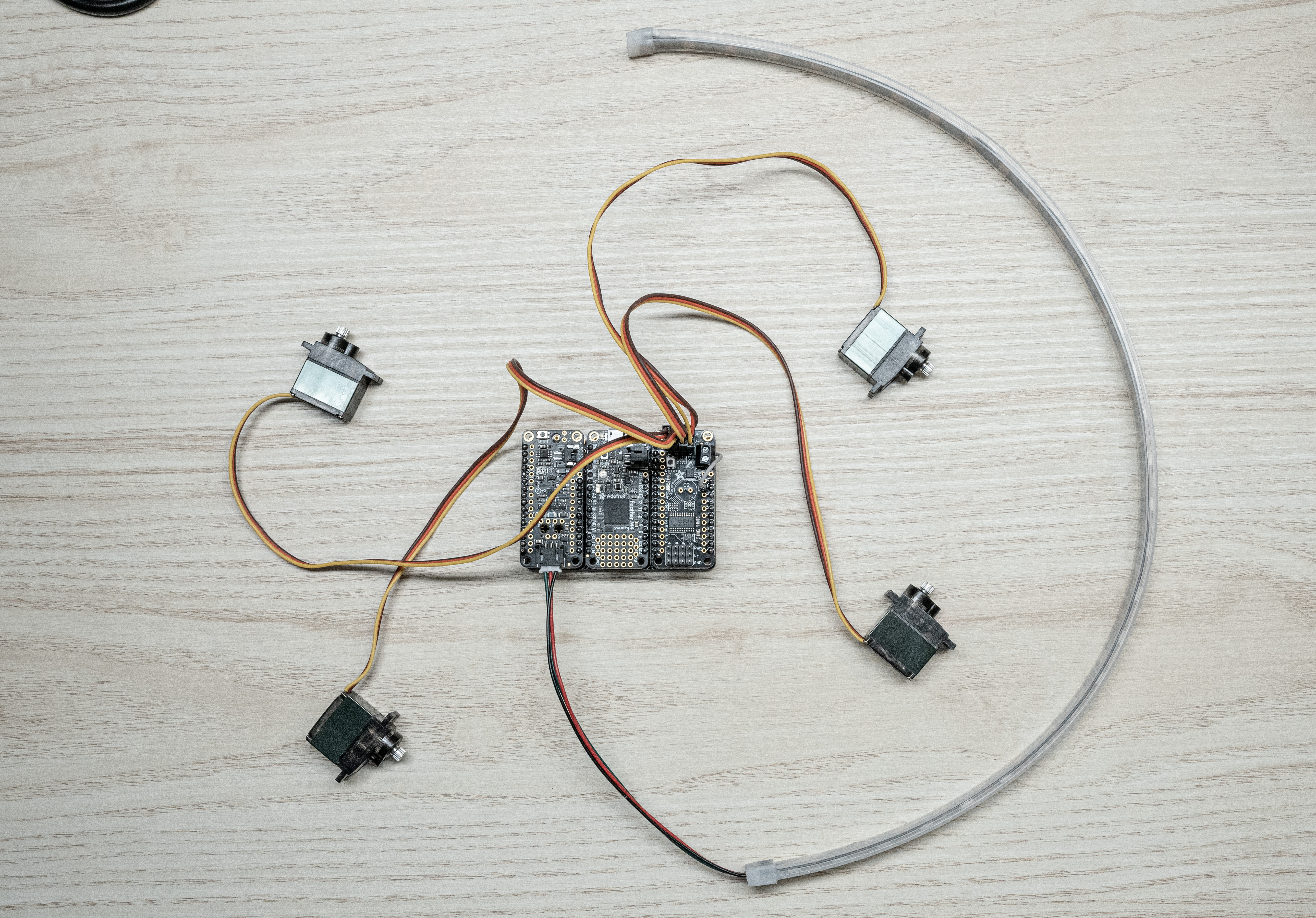
Plug your servos and LED strip into the designated connections on the PCC:
- The LED strip plugs into the prop-maker featherwing
- The servos plug into channels 0-3, with the yellow signal wire of
the servo facing the Adafruit logo on the PCB.
Software Setup
Now it’s time to download the AVR GUI program.
Windows
Go to the latest
AVR software release
and download the AVRGUI.<hash>.exe file. Like QGroundControl,
you may need to bypass some warnings about being an untrusted file.
Select “Keep”
Select “Keep anyway”
For Linux and MacOS, we recommend running the AVR GUI from source. You’ll need
to have Python 3.9 or Python 3.10 installed.
For Linux users, here’s how you can easily install Python 3.10:
sudo add-apt-repository ppa:deadsnakes/ppa
sudo apt install python3-pip python3.10 python3.10-venv
sudo -H python3.10 -m pip install pip wheel --upgrade
For MacOS users, go to the Python releases page for MacOS and download an appropriate
installer: https://www.python.org/downloads/macos/
Now, run the following commands to clone the code repository where desired,
and setup the dependencies.
# clone the repo
git clone https://github.com/bellflight/AVR-2022
# cd into the repo
cd AVR-2022
# create a Python virtual environment
# You may need to replace `python` here with `python3` or `python3.10`
python -m venv .venv
# activate the virtual environment
source .venv/bin/activate
# install the dependencies
python scripts/install_requirements.py --directory GUI
# run the application
python GUI/app.py
In the future to run the application, you’ll just need to activate the virtual
environment first:
cd AVR-2022
source .venv/bin/activate
python GUI/app.py
To deactivate the virtual environment, run:
PCC Tester
Before, you launch the application, plug the PCC into your computer with a
MicroUSB cable. The application will not recognize anything plugged in after it starts.
Now, launch the application. You should be presented with a screen like this:
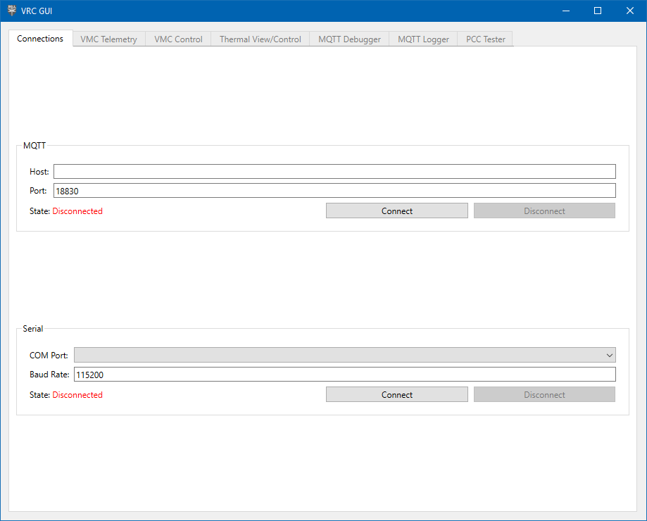
AVR GUI Home Screen
In the Serial section, select the COM Port your PCC enumerates as. Click “Connect”
and the “PCC Tester” should now be enabled (we’ll talk about the other tabs in
a later section).
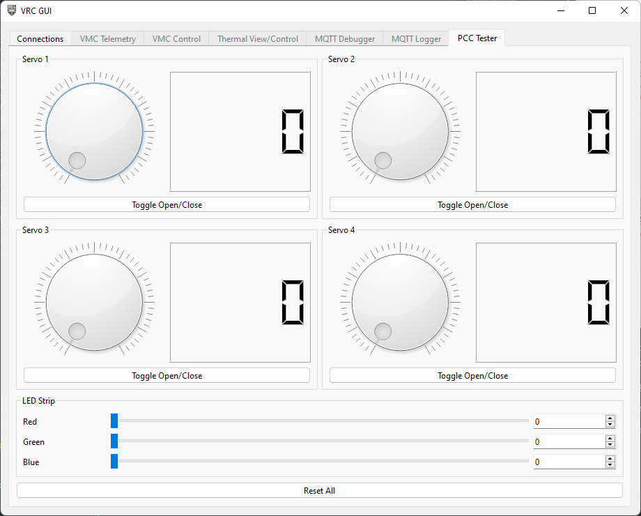
PCC Tester Tab
Click around and try the different buttons,
your PCC should light up the LED and move some servos!
If some parts of the PCC work (such as the servos but not LEDs), this is
likely a hardware issue. Double check all of your solder connections
to make sure they are properly electrically connected and not shorting
anything they shouldn’t be.
If nothing on the PCC works:
- Make sure you selected the right serial port in the GUI. Sometimes phantom COM
ports show up on Windows which you will be able to select, and won’t do anything.
- Make sure your firmware flashed correctly. Follow
the steps
again and pay close attention.
- Finally, as stated above, double check all of your solder connections.
10 - Vehicle Management Computer (VMC)
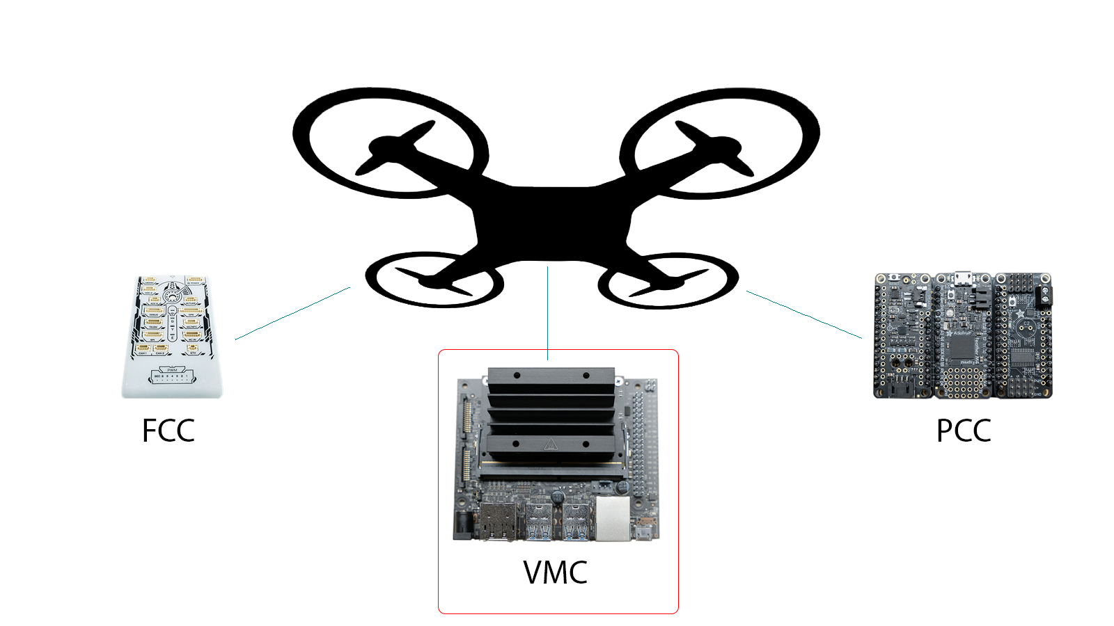
10.1 - Preparing the Jetson
Physically assemble the Jetson
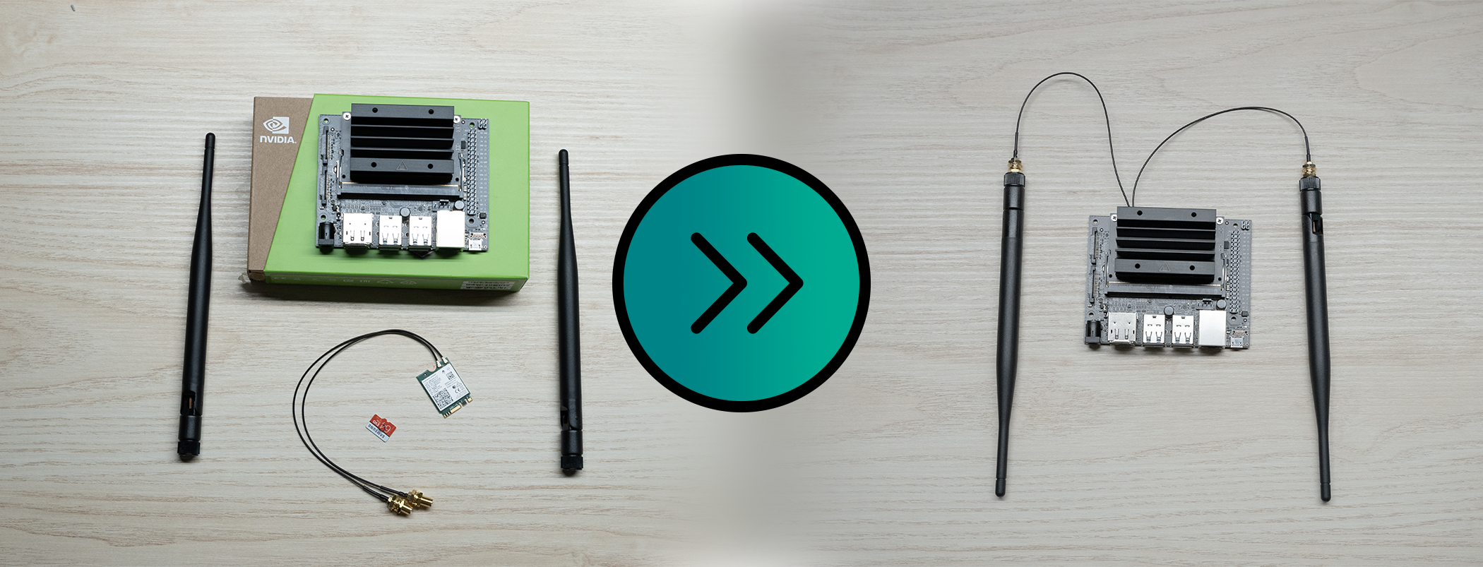
- Unbox your Jetson
- Unbox WiFi Adapter
- Unscrew Jetson top
- Push the tabs out
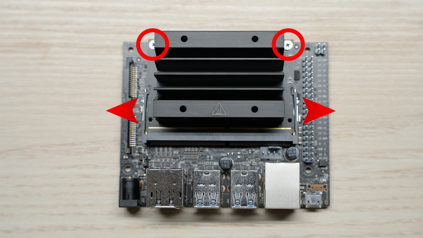
- Pull out the Jetson Nano Module
- Pull black screw
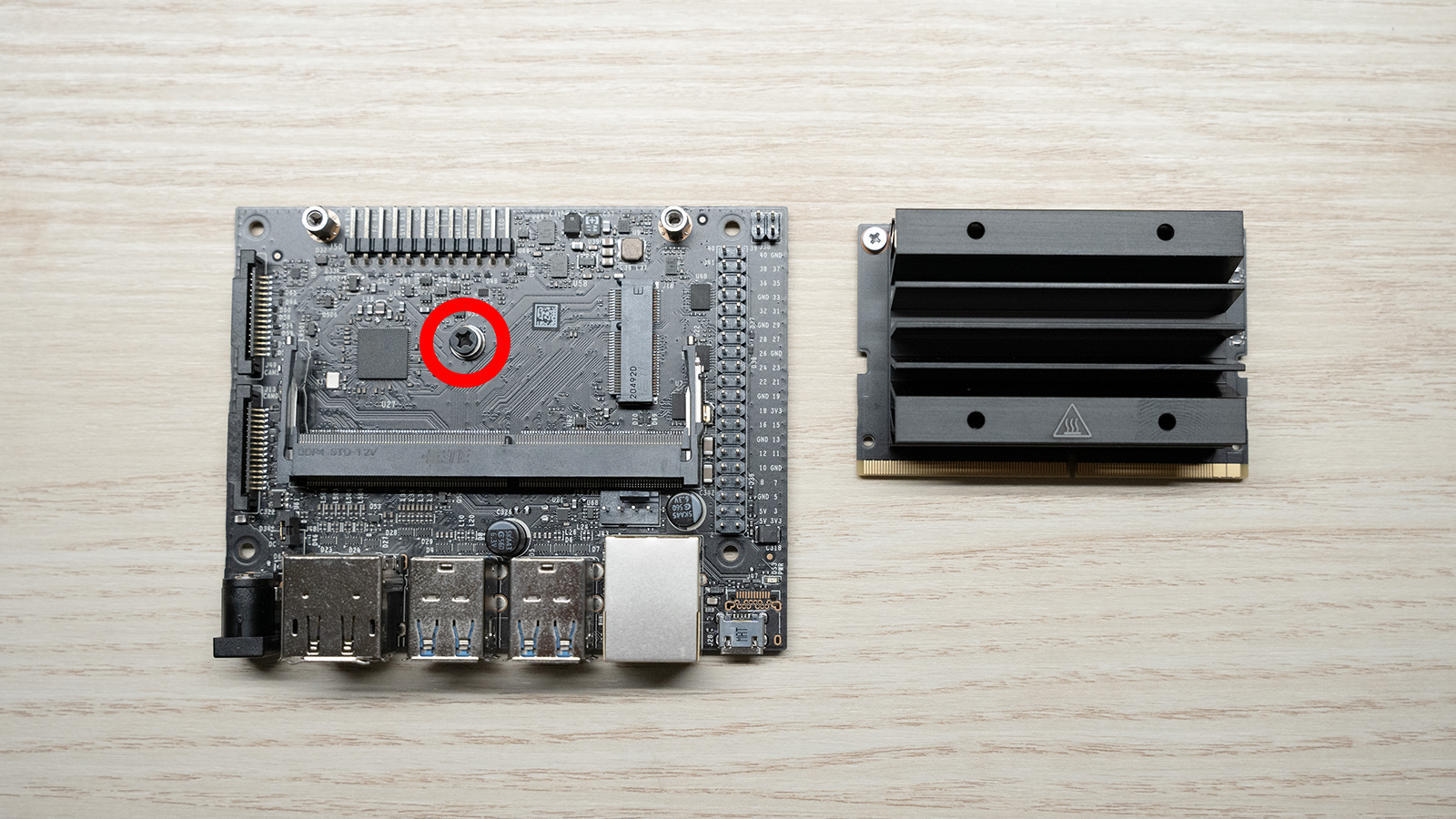
- Slide in the WiFi card
- Put in black screw
- Slide module back into place
- Replace screws
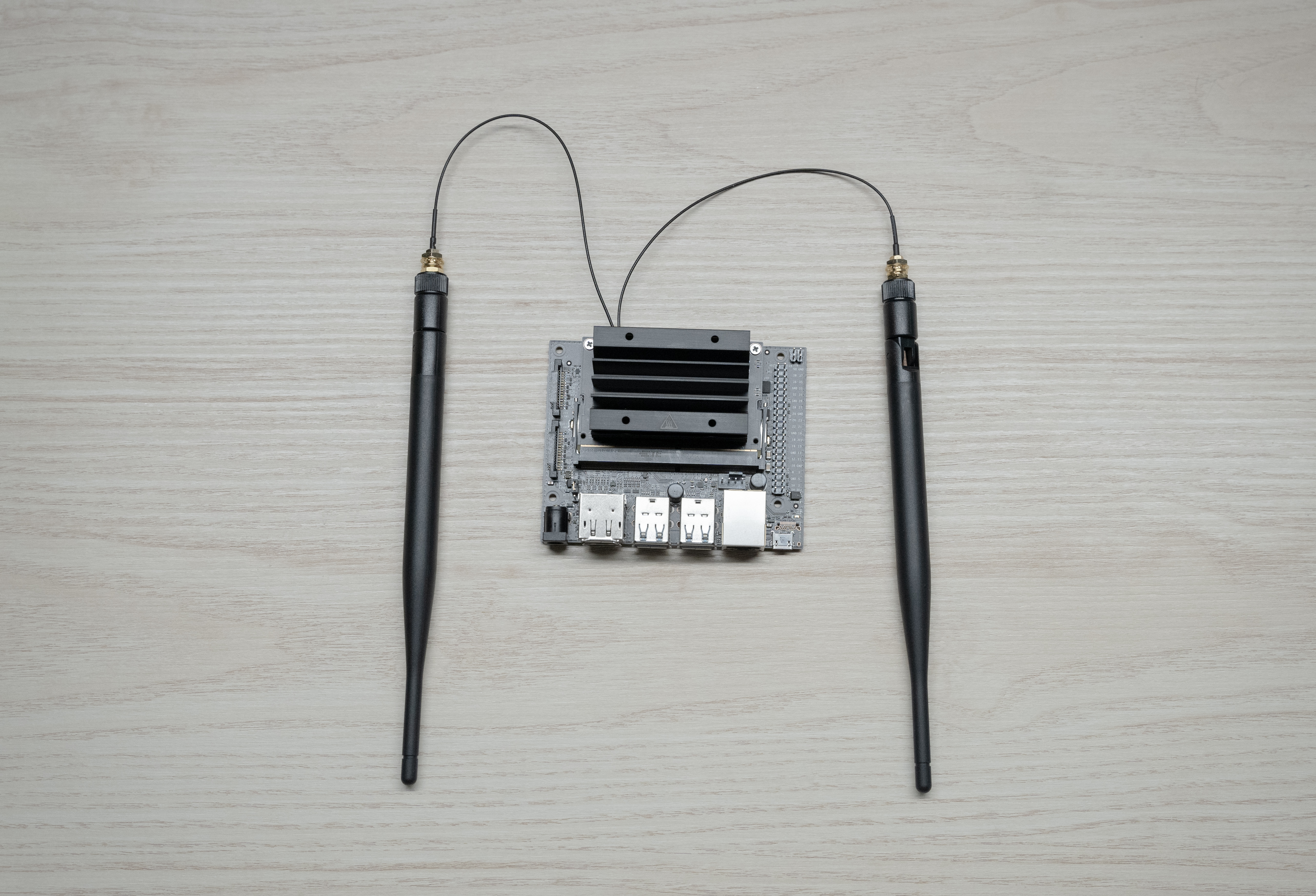
Success
Now that your Jetson assembly is complete, please be sure to insert the micro SD card. The micro SD card contains Ubuntu (Linux) and the default VMC software pre-installed.
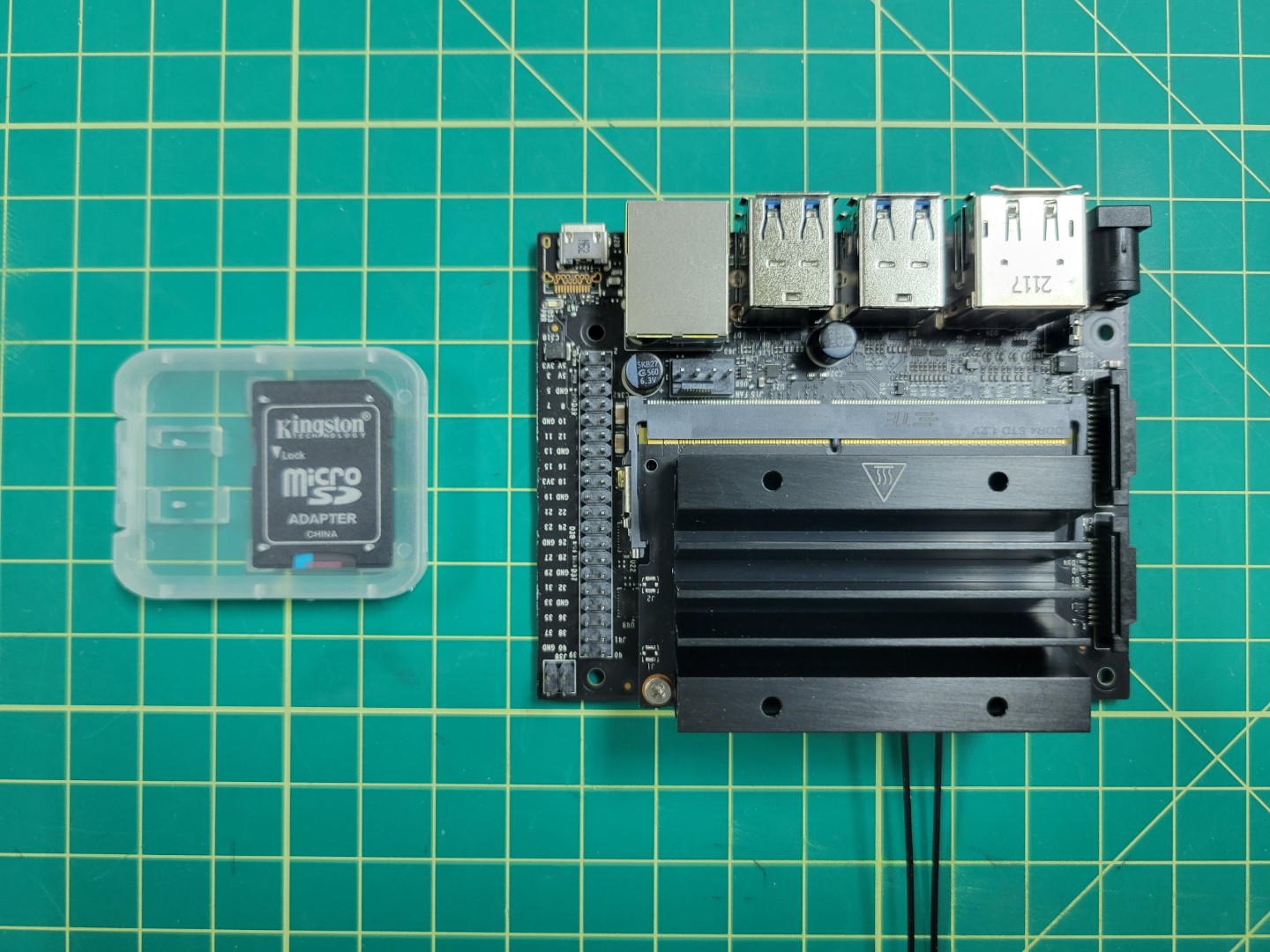
Micro SD with software pre-installed
Make note of the orientation of the micro SD card in the photo below.
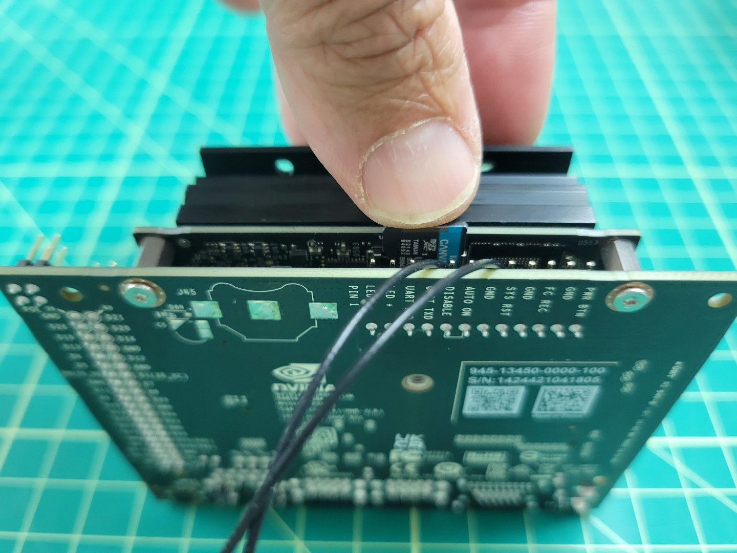
Inserting the micro SD card into the Jetson
11 - Advanced Drone Assembly
Please make sure you’ve successfully built and flown your basic AVR drone.
You will be making some extensive modifications to your drone in
preparation for advanced assembly.
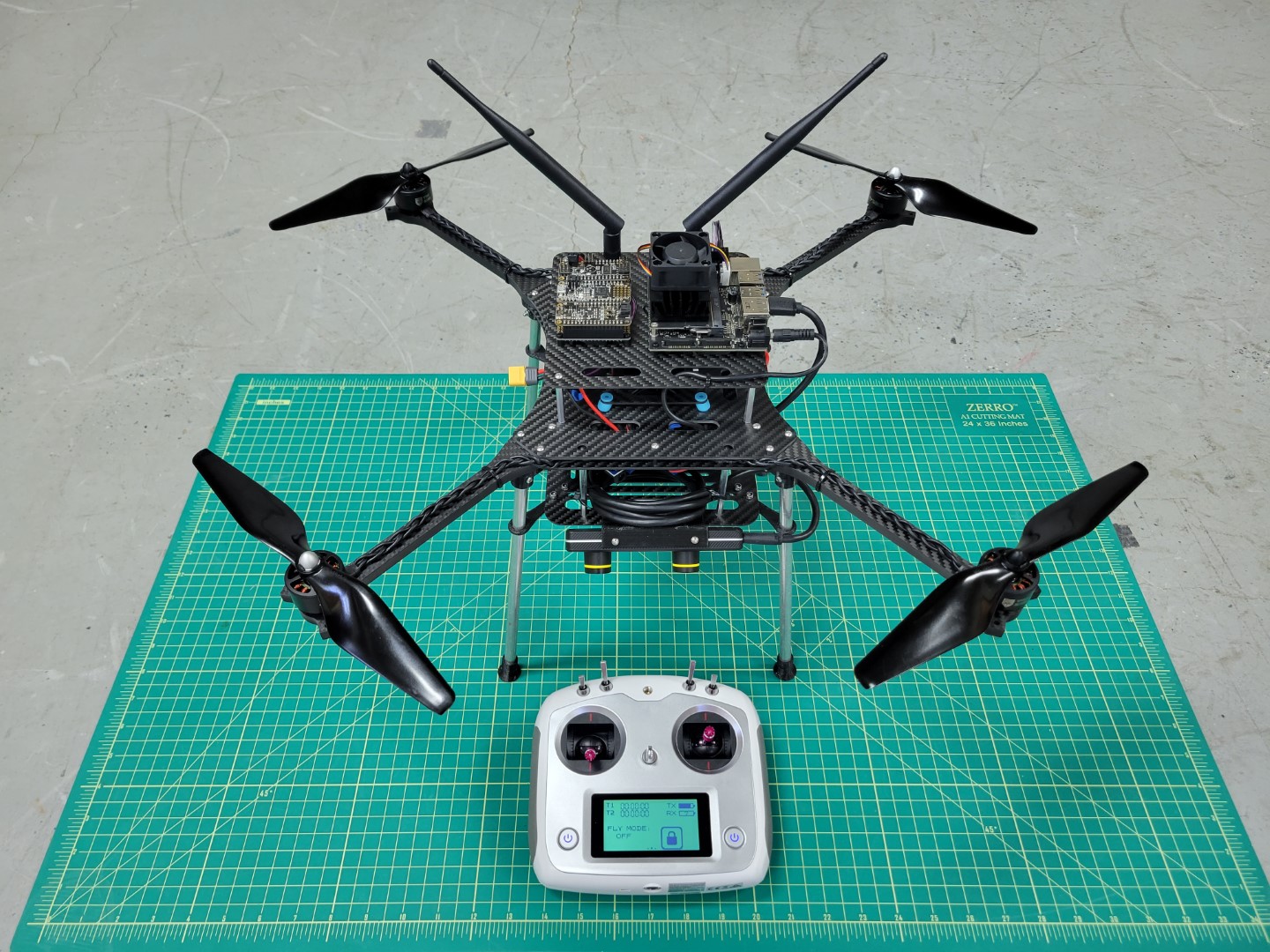
AVR advanced drone assembly (front)
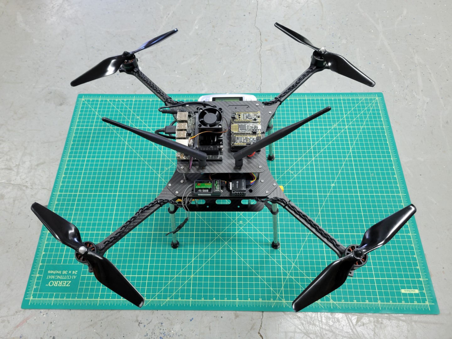
AVR advanced drone assembly (back)
The modifications for advanced assembly will require some disassembly and the following
additions to your drone:
- 3D printed components
- For mounting various cameras and peripherals
- Power setup for VMC and PCC
- Power distribution board soldering
- Y-cable to split power between PDB and ESC
- Buck converters for powering VMC and PCC
- Telemetry cable
- For communication between VMC and FC
- Vehicle Management Computer (VMC)
- Runs AVR code
- Interfaces with external sensors
- Provides wireless interface with PX4
- Peripheral Control Computer (PCC)
- For LED and servo actuation
- ZED Mini Tracking Camera
- For real-time mapping of the environment
- For position hold
Block Diagram for the Advanced Drone
11.1 - VMC and PCC Power
Overview
Two main components of your advanced build are the Vehicle Management Computer (VMC), which runs the AVR software stack and the Peripheral Control Computer (PCC), which will allow teams to manually and programmatically control the LED ring, actuate up to four servos, and control the laser.
This section will walk through the necessary steps for providing adequate power to both the VMC and PCC.
This will be done with two separate buck converters.
The main battery of your AVR drone is 16.8V fully charged.
The required input voltage for the VMC and PCC are 5V,
therefore the buck converters will step the voltage down to a usable 5V.
Power Wiring Diagram
This section will work its way from the battery out to the VMC & PCC.
Y-Cable
The Y-cable is the cable that splits the battery power into two directions: one for the ESC, and one for the PDB.
To create the wire cables use 3 of the 4 pre-soldered XT60 cables from the kit, 2 females and one male.
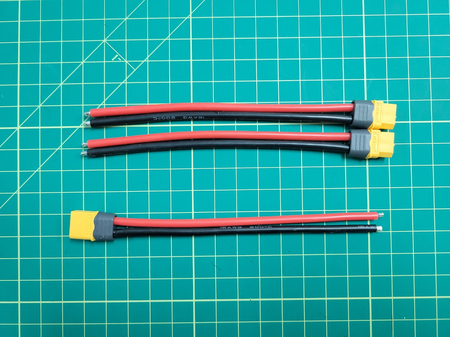
XT60 cables
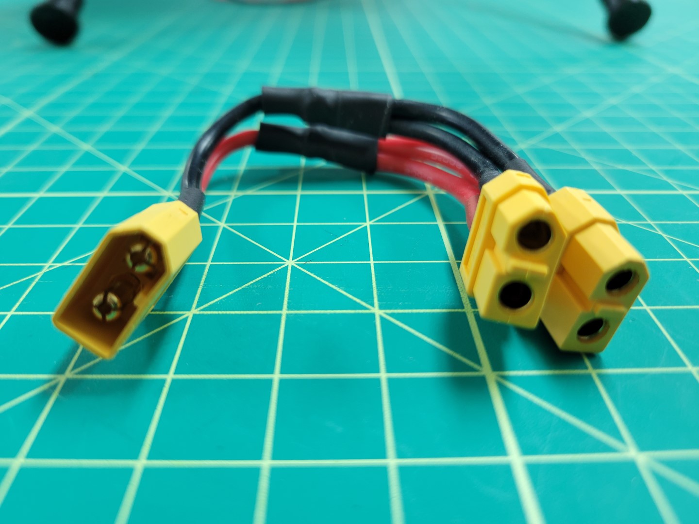
XT60 male (left) and female (right) connectors
Firstly, cut each cable to approximately 2 inches and solder the ends so that they are ready to combine. The end result should look similar to the following.
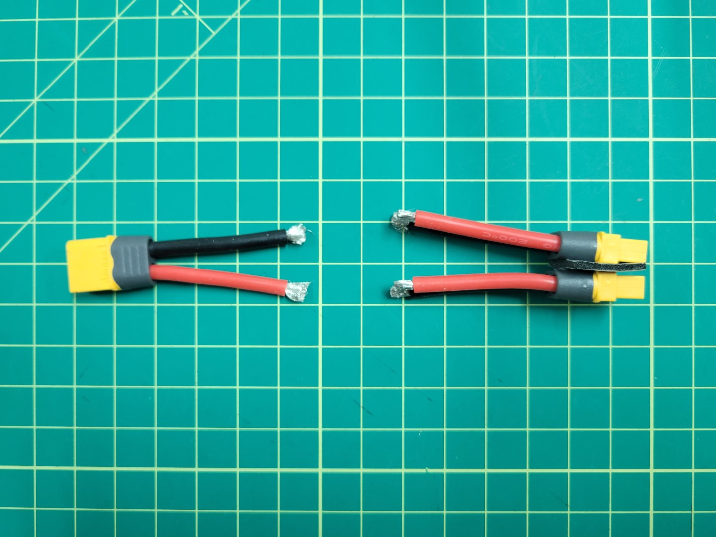
XT60 cables preparation
Next, place heat shrink large enough to slide over the 3 cable solder joint on the side with 1 male connector. Then, solder the 3 ground (black) cables together.
Pull the heat shrink down over the end of the connection and apply heat.
If you have access to a heat gun or a lighter this will work well.
Alternatively, you can use the side of your soldering iron to apply heat and let the tubing shrink over your connectors.
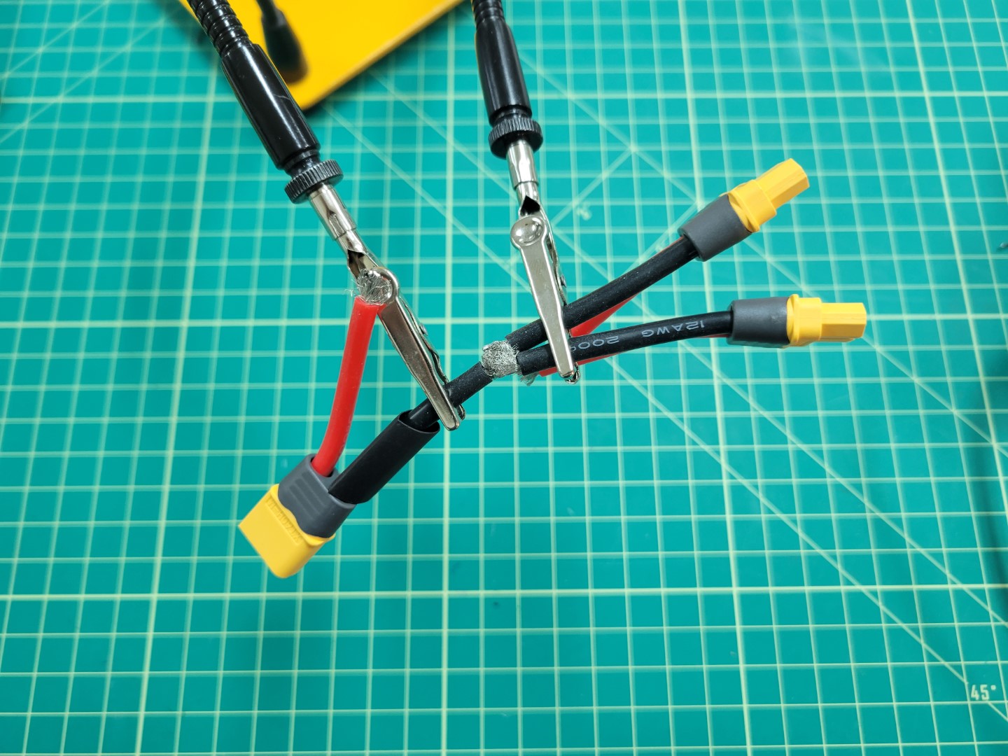
Soldering XT60 cables
Repeat for the voltage (red) cables.
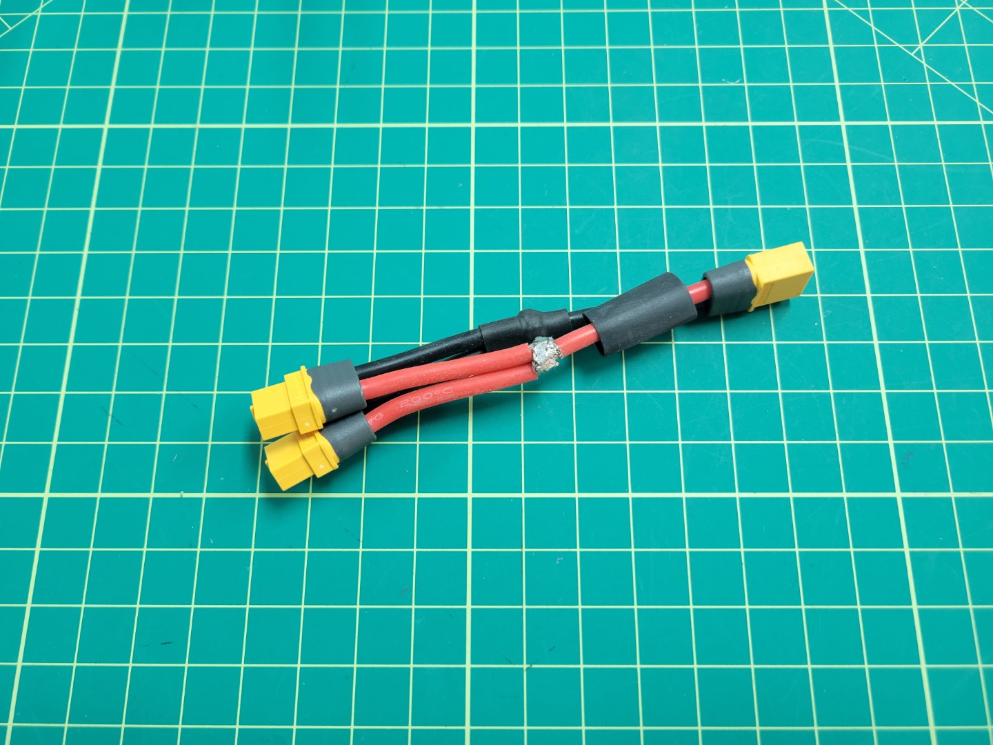
Soldering XT60 cables
Your finished cable should look like the photo below.
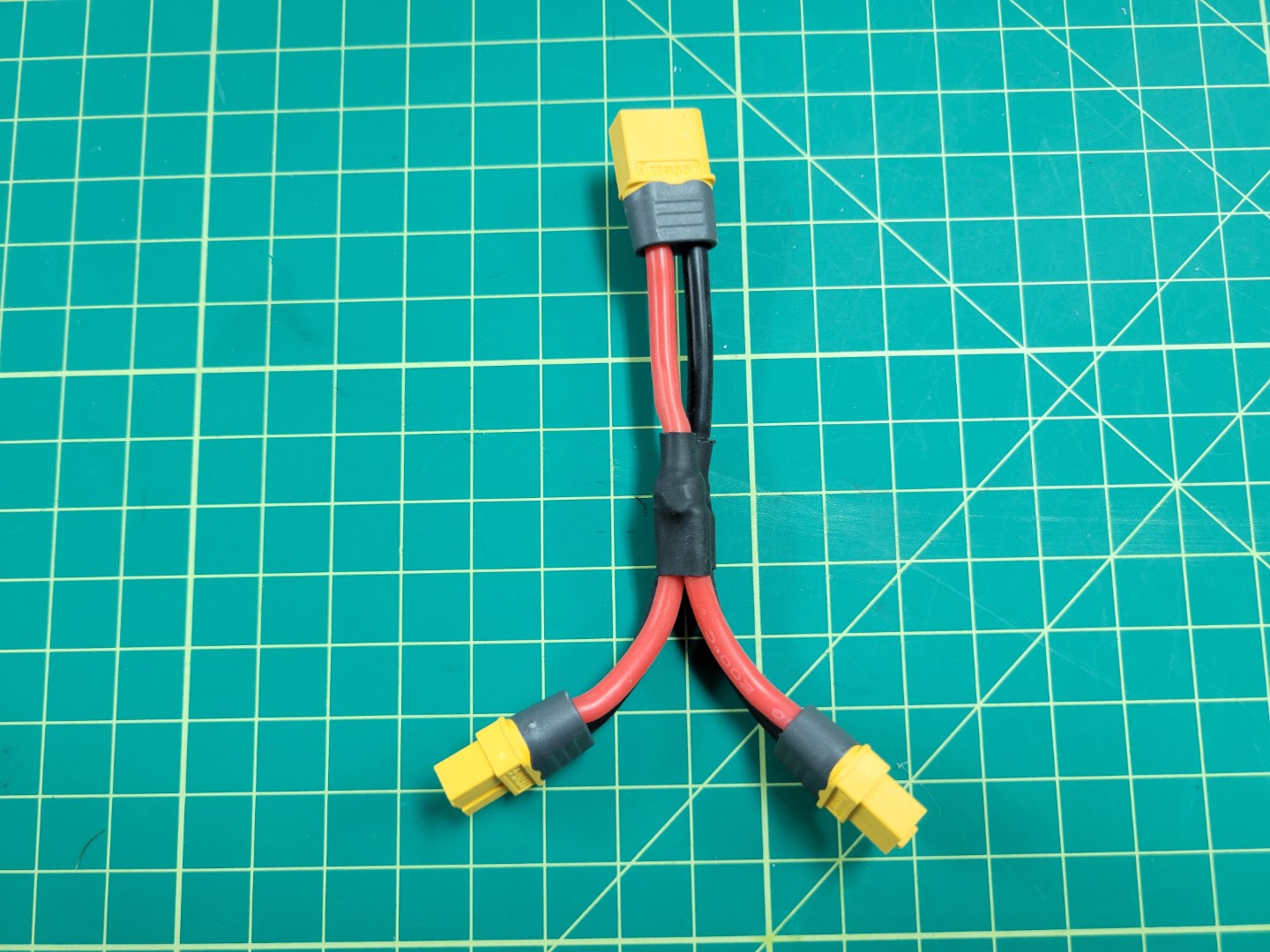
Y cable with 1 male and 2 female connectors
Before installing the buck converters, the Power Distribution Board (PDB) will need to be soldered correctly. The PDB will allow us to split off power from the battery to each of the buck converters.
The first step is to solder on the battery leads to the PDB.
To do this cut 1 male XT60 cable to about 2 inches and tin the ends as we did with the y-cable above.
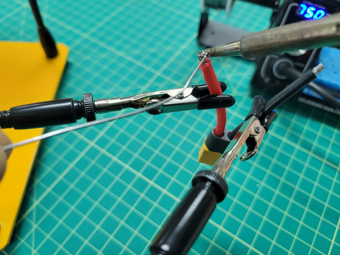
Tinning male XT60 leads
Warning
Soldering the larger pads on the PDB requires skill and patience. If possible, we recommend using a flat tip on your iron instead of the normal pointed tip. This will allow for much better heat transfer.
We recommend watching this video that goes into great detail on soldering. It’s lengthy so at the very least you should scrub through it before attempting to solder the XT60 to the PDB.
You do not want the PDB to slide around while soldering. One of our favorite tricks is to use Blu Tack to hold components in place.
Start the process by tinning the Batt +/- pads as shown in the photos below.
A good temperature to aim for is between 750 and 800 degrees Fahrenheit.
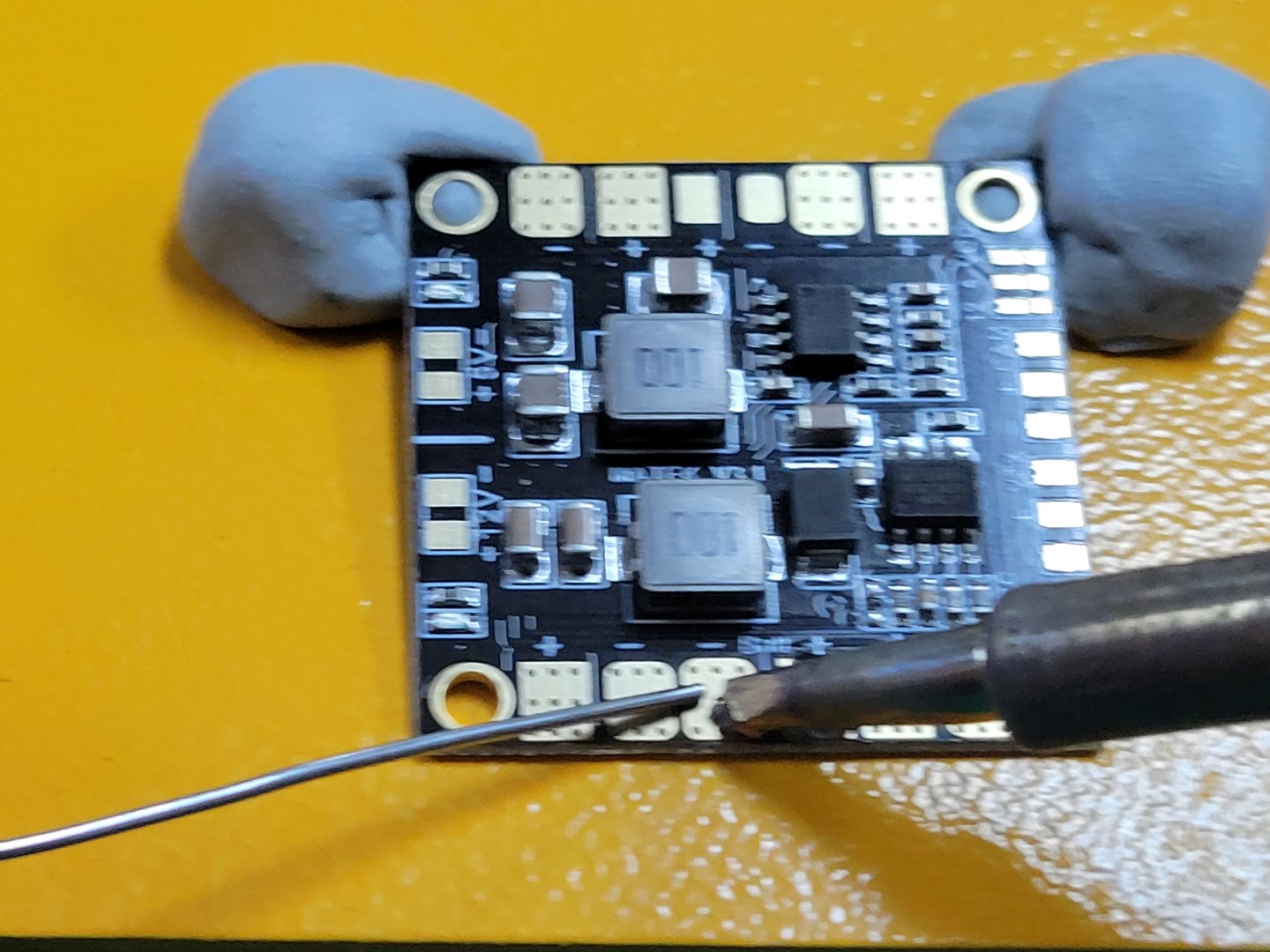
Tinning PDB batt +/- pads
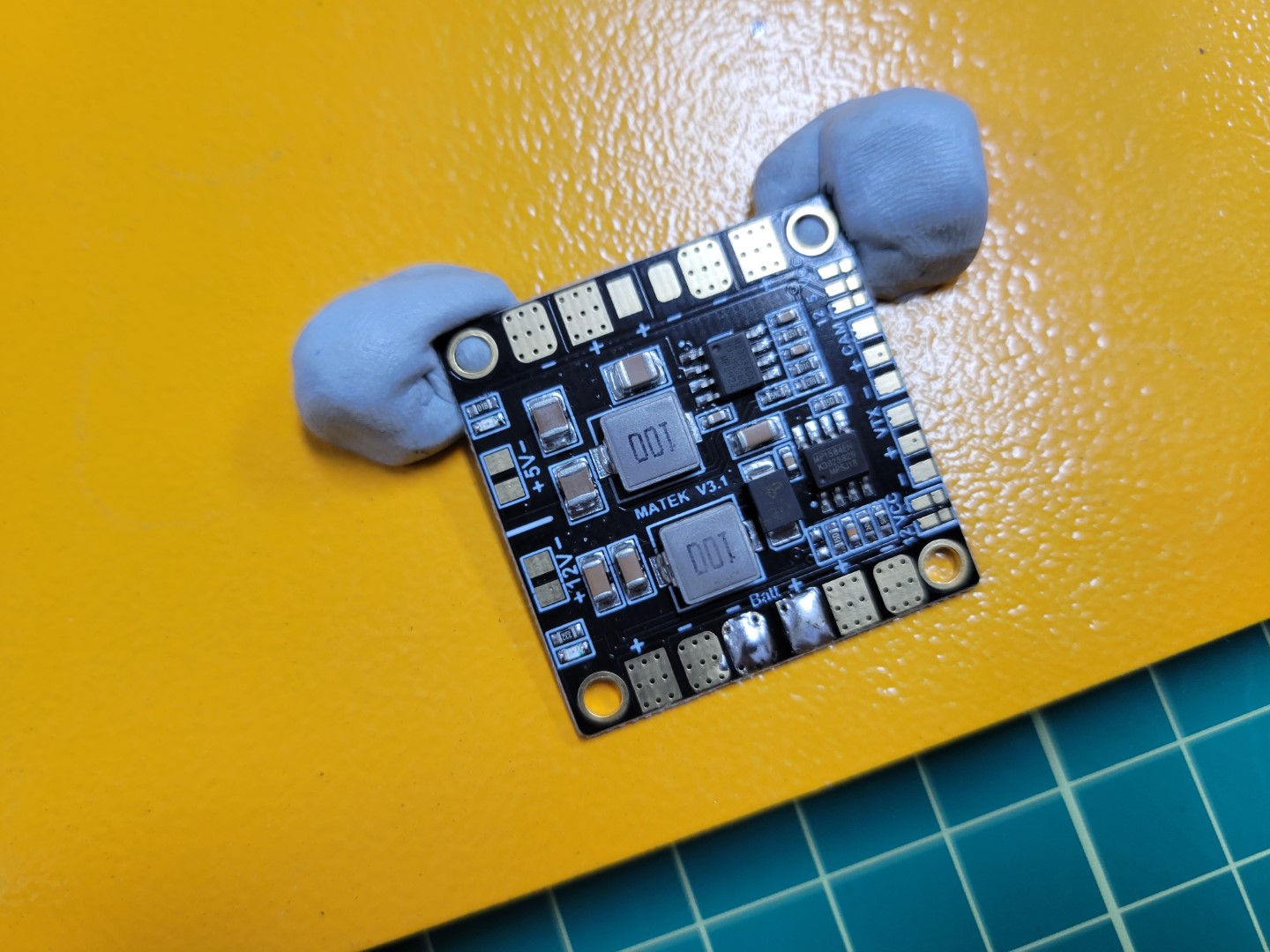
Pads tinned and ready for input wires
Place the positive wire onto the positive pad and set the tip of the iron on top.
Do not apply too much pressure as you do not want the wire to spread out.
The iron should heat both the wire and the pad to form a single solder joint.
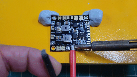
Animation of soldering wire to PDB pad
Repeat this process for the negative wire.
Your completed PDB will look similar to the one below.
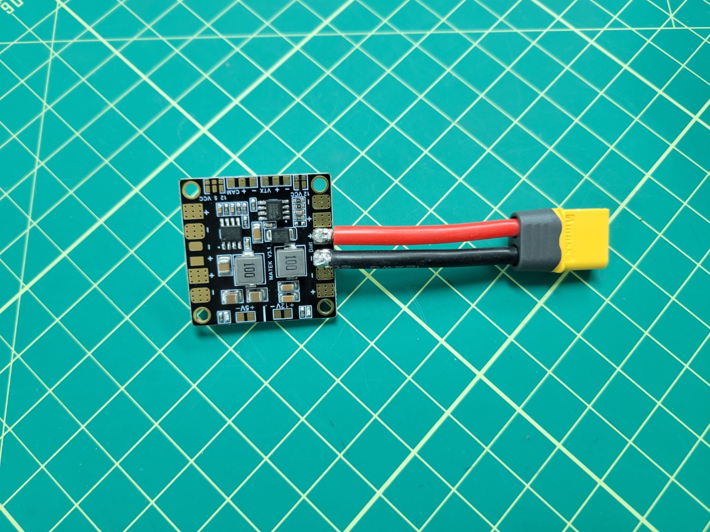
PDB input soldering complete
PDB Output Soldering
In the photo below you will notice two identical buck converters,
one for powering the VMC and the other for the PCC.
This section will walk through the necessary wiring to supply power to the buck converters.
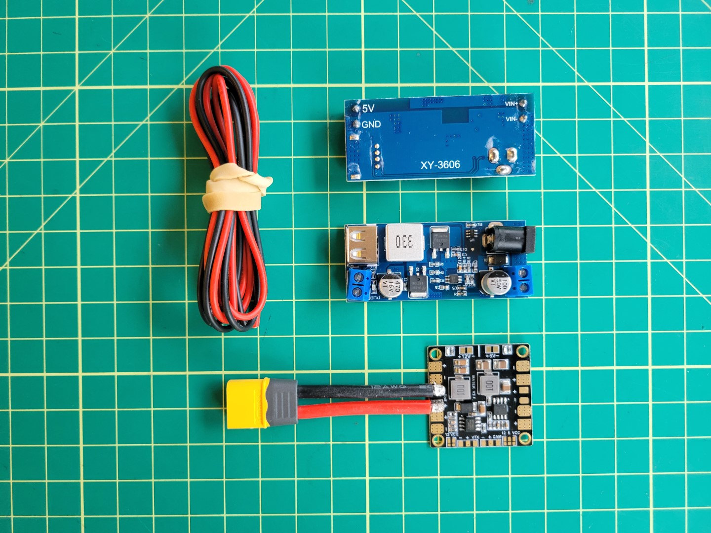
PDB, wires, and buck converters
Cut approximately 8" of wires; 2 black and 2 red.
These will be used to connect each of the buck converters to the PDB.
On the opposite end of the PDB there are two sets of pads that we’ll tin for soldering.
Heat the pad using the tip of the soldering iron and
feed the solder onto the pad as shown in the photo below.
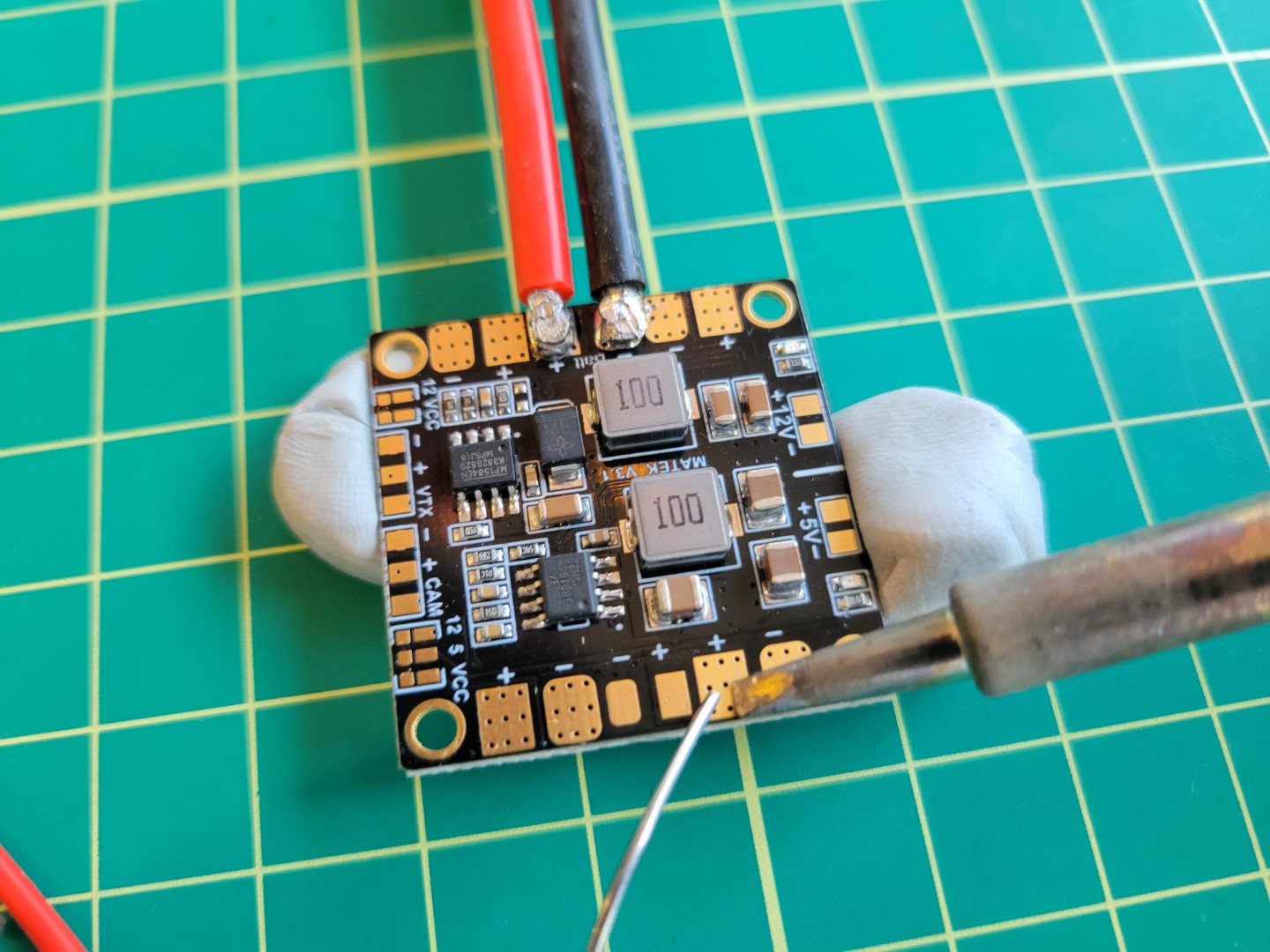
Soldering the PDB
Once the pads are pre-tinned it should like the following.
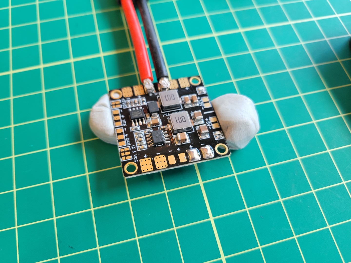
Pre-tinned Solder Pads
Next, apply solder to the wires to pre-tin them.
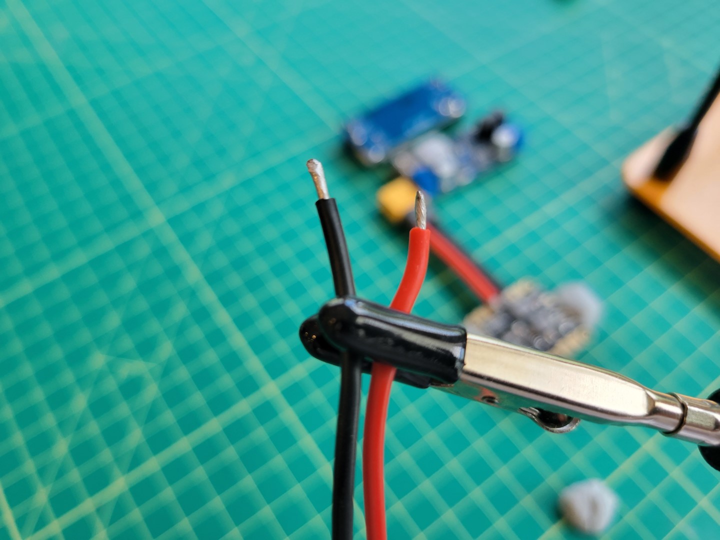
Pre-tinned Wires
After pre-tinning everything, place each lead on the corresponding pad and gently push
the soldering iron down.
Like we did with the XT60 connector we want to make sure to apply heat long enough for
the solder on the pad and wire to join.
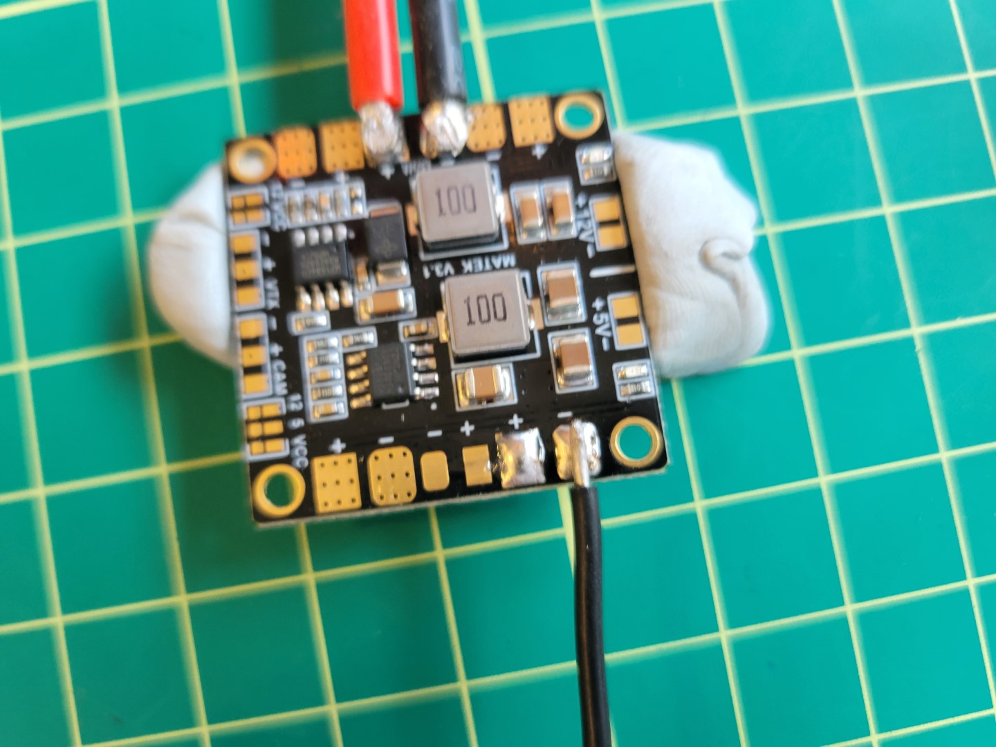
Soldering wires to pads
Repeat this process for the other two wires.
After successfully soldering the positive and negative wires to the PDB,
use a multimeter to run a continuity test.
This will ensure that there are no shorts between the positive and negative terminals.
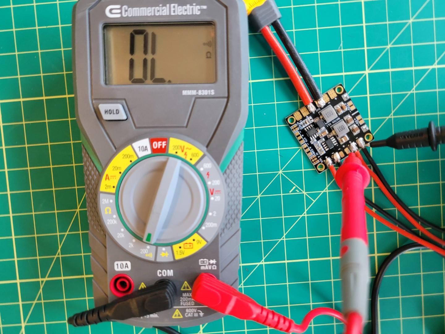
Checking connections
You should now be at a place where you have the PDB soldered as shown in the following photo.
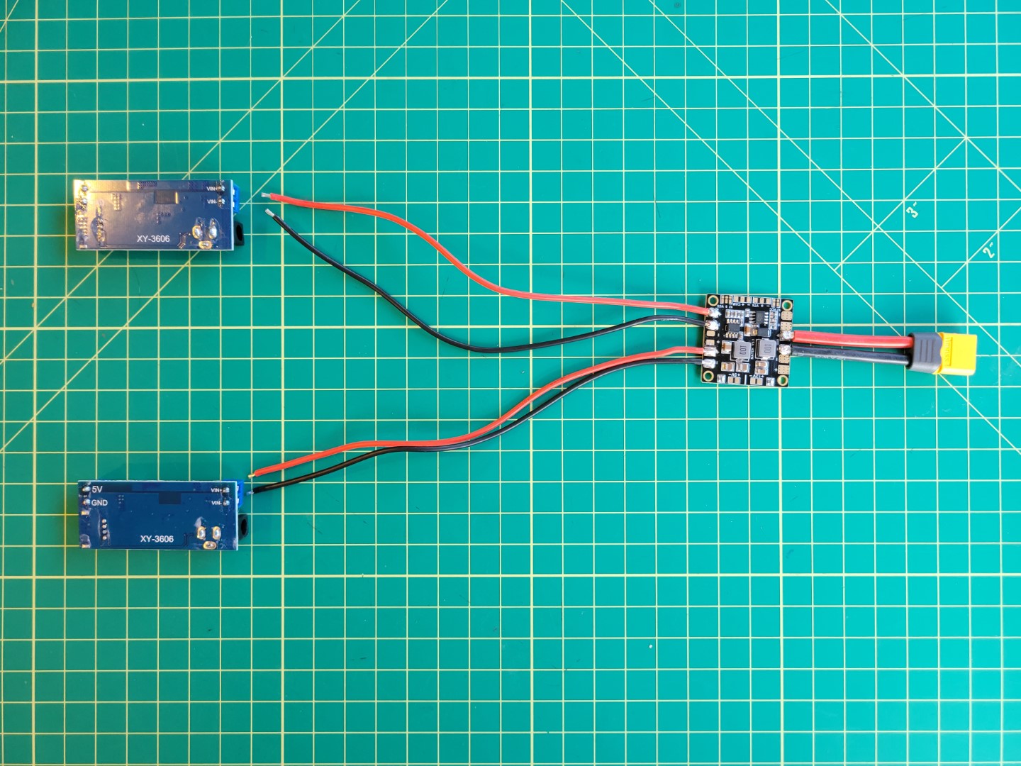
Power Distribution Layout
Finally, place the PDB on top of the ESC standoffs and secure using M2.5 nuts from your AVR kit.
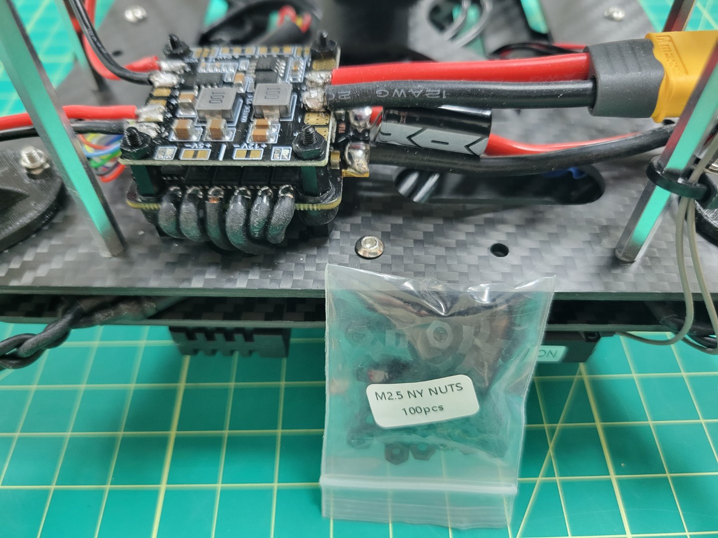
Mounting the PDB
11.2 - Buck Converter Mounting
Overview
Wire management is an important part of any drone build.
It will make your build easier to maintain, look professional, and keep wires from potentially getting caught in your drone’s propellers.
In the previous section we pre-soldered the VMC/PCC power wires and mounted the PDB.
Now we will focus on wiring and mounting the buck converters.
The power wires from the PDB will be run through the mid-plate assembly to the front of the AVR drone.
This is necessary to make sure the wires do not interfere with battery mounting, which we’ll cover in an upcoming section.
Note
A quick reminder that we try to supply you with best practices for your drone assembly.
In some cases you may chose to venture out and find a better way to accomplish a task.
That’s completely fine and you’re highly encouraged to do so!
We even encourage you to share a given solution in
our forums.
Wiring
The PDB and ESC are both mounted near the right rear of the frame.
The buck converters will be mounted near the front of the frame.
This means we need to run the cables up through the mid-plate assembly and drop them down in the front of the frame.
Feed the wires into the mid-plate assembly and zip tie them to the mid-bottom plate as shown in the photo below.
Securing these wires is important as you don’t want them to interfere with battery mounting.
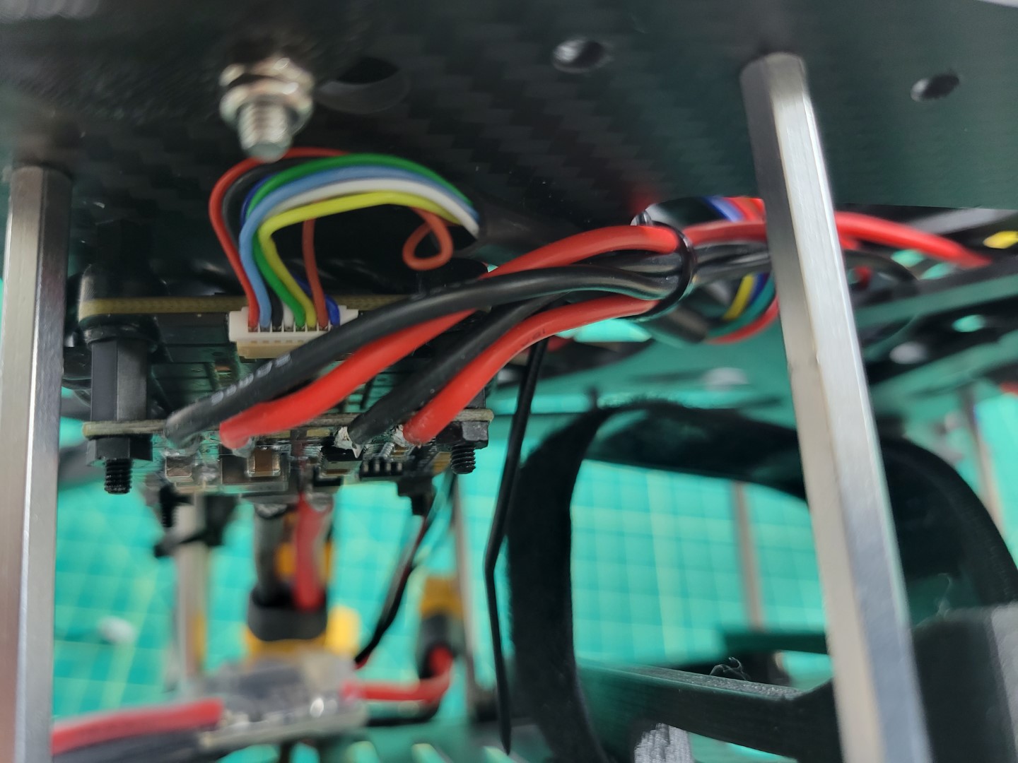
VMC and PCC power leads run through mid-plate assembly
Drop the wires down through the two large oval cutouts in the mid-bottom plate as shown in the photo below.
Tip
It is much easier to feed the wires through the mid plate assembly by temporarily pulling
your excess motor/ESC wire out of the frame to free up space.
Be sure not to accidentally disconnect them!
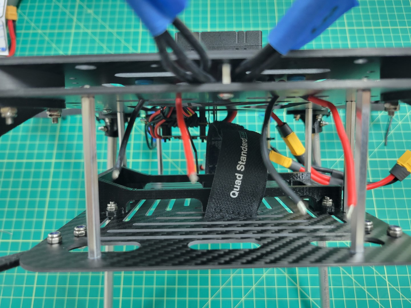
VMC and power leads ready to connect to buck converters
Mounting
We will mount the buck converters using the 3M double-sided tape provided in your AVR kit.
The solder joints on the bottom of the buck converters stick out a good bit so we will double-stack tape on each end.
The reason for this is that we do not want to the solder joints to accidentally make contact with the carbon fiber plate.
This could lead to a short circuit. Cut one of the 3M squares into four pieces as shown in the photo below.
3m tape cut into four squares
Double stack the tape on each end of the buck converter as shown in the photo below.
Repeat the process for the other buck converter.
Double stacked 3M tape on buck converter
Before securing the buck converters to the AVR frame we will connect the input leads to the screw terminals on each buck converter as shown below.
Warning
Make sure you are connecting the input power leads to the terminals labeled VIN+ and VIN- on the buck converter.
These are located next to the barrel jack.
Tip
You want to tightly screw down on the wires otherwise they may come loose.
If you find the wires are coming loose you can always remove them, tin them with solder, and try screwing down on them again.
Power wires connected to buck converter terminals
Take the remaining 18 gauge wire (the wire you used to supply input power from the PDB to each buck converter) and connect it to the output terminals on the PCC buck converter.
The PCC buck converter will be on the left side as drone is facing you.
You can see the output wires on the left side of the photo below.
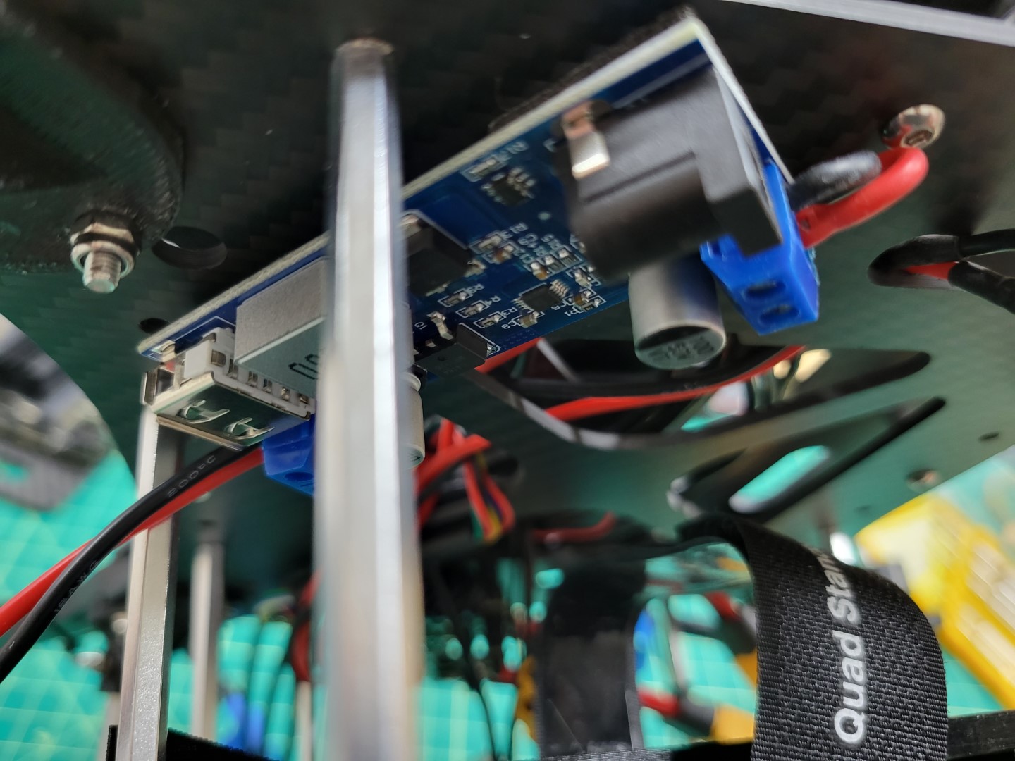
PCC buck converter with output wires on left and input wires on right
VMC power is supplied with a barrel plug. Find the cable with the barrel plug in your kit and cut it to 8".
Remove the shielding and expose about 1/8" from the positive and negative wires as shown in the photo below.
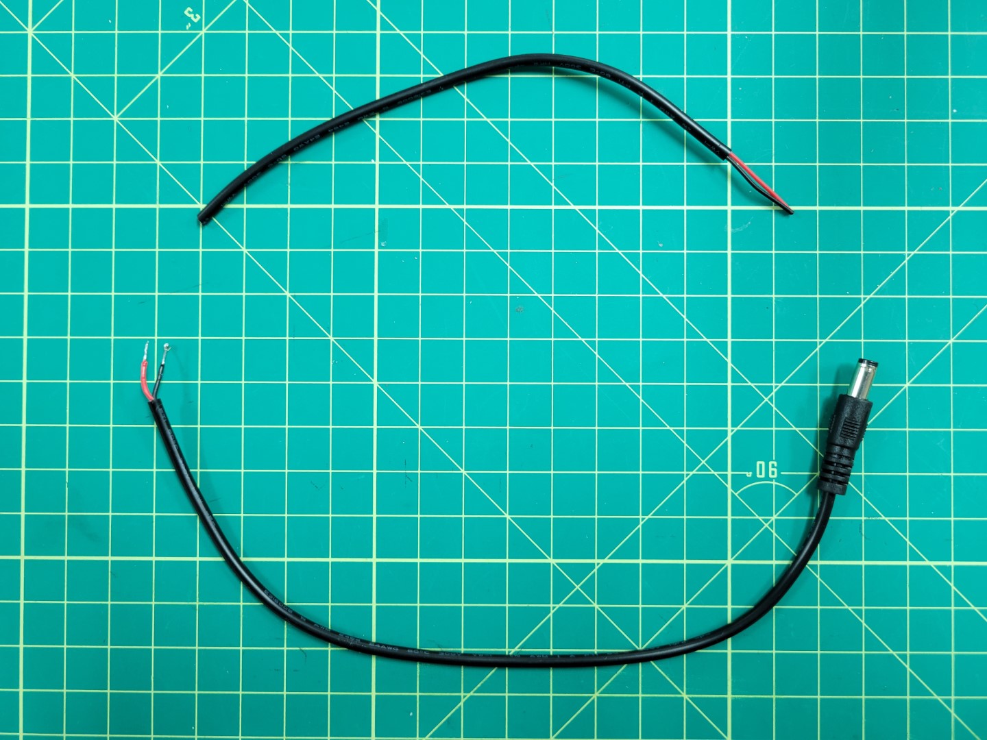
Prepping power cable for VMC
Connect the positive and negative leads to the output terminals on the VMC buck converter.
Once again, screw down tightly on the terminals so that the wires do not come loose.
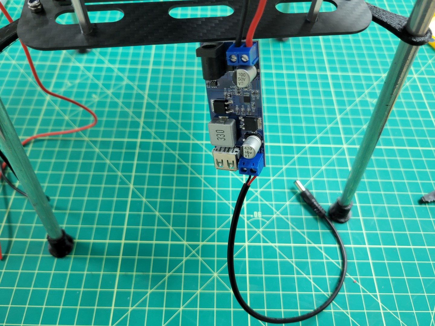
VMC buck converter wired up with barrel plug
Stick the PCC buck converter on the left side of the bottom mid-plate and the VMC buck converter on the right (as the front of the drone is facing you).
Place each buck converter at a 45 degree angle with the output leads pointed towards each side of the frame.
The photo below shows the PCC leads on the left side of the frame and the VMC barrel plug on the right.
Note
Make note of the yellow circles in the photo below. These are the access holes for mounting the standoffs for the top accessory plate.
Be sure not to cover these holes when mounting the buck converters.
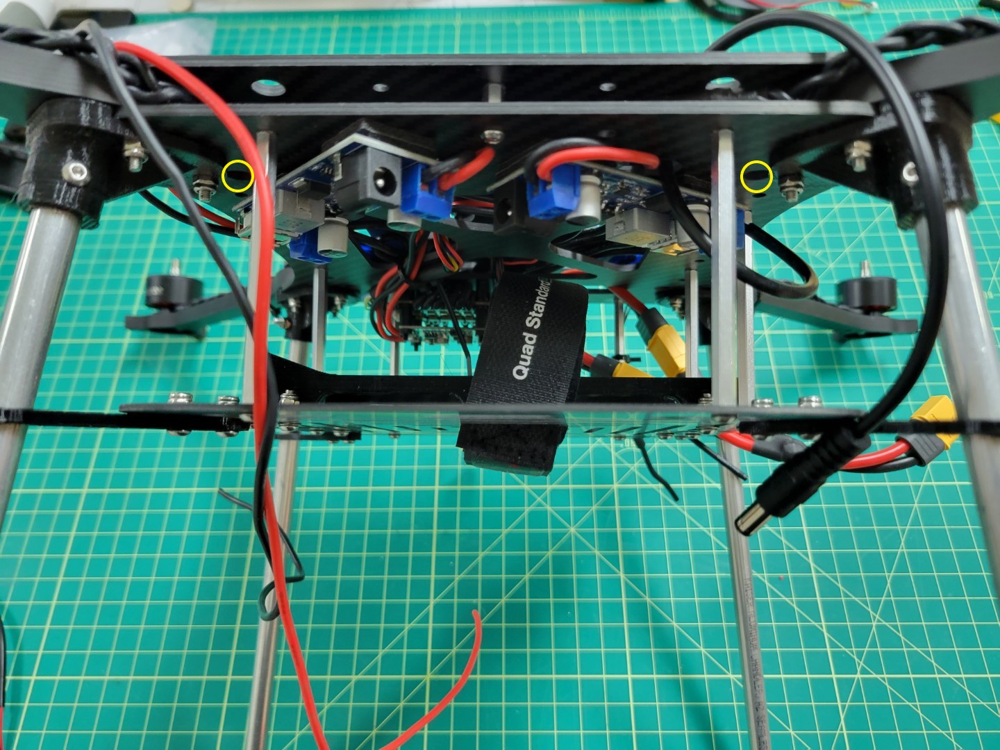
Buck converters mounted at 45 degree angle
The photo below shows the right side of the frame and clearance for the battery to slide into the tray.
The PCC will be mounted and powered from this side of the frame.
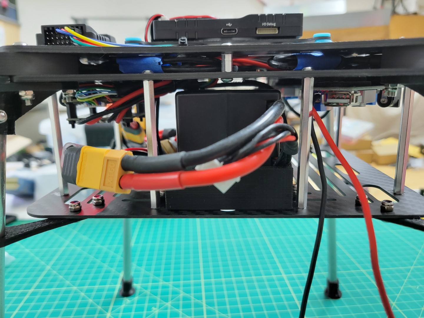
Right side battery clearance
The photo below shows the left side of the frame where the battery can slide into place without any obstruction from the buck converters.
The barrel plug hangs off this side of the frame and will be used to power the VMC.
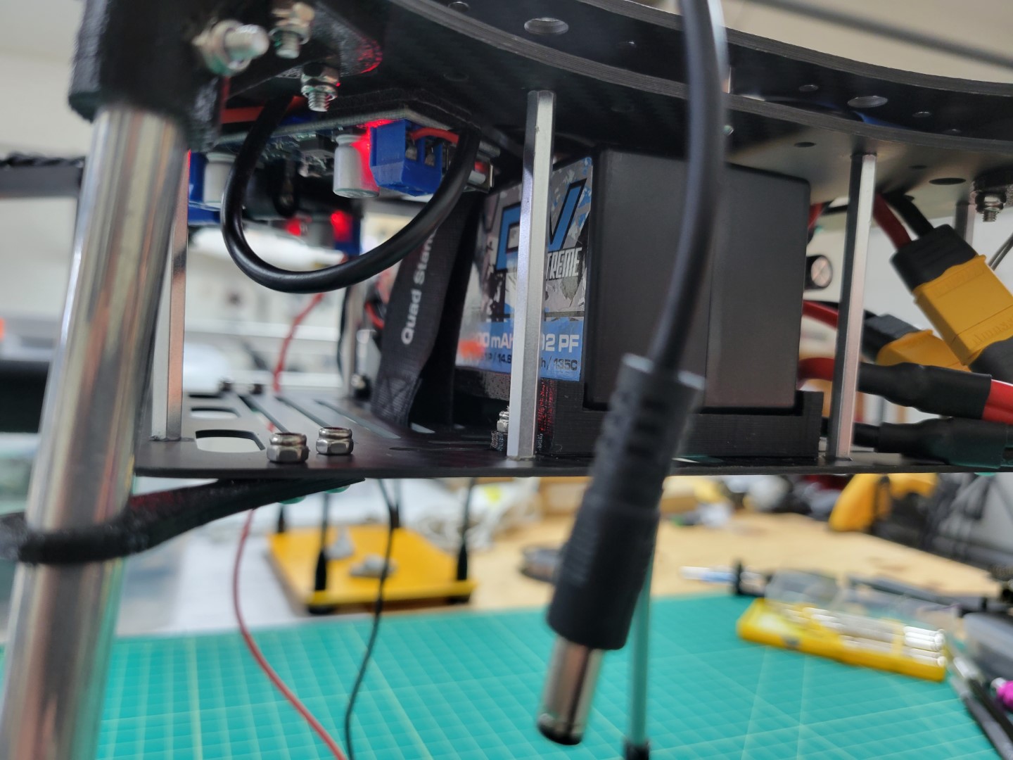
Left side battery clearance
Take a quick look at the wiring orientation from a top down perspective.
In the next section we will build the top plate assembly and install it over the FC.
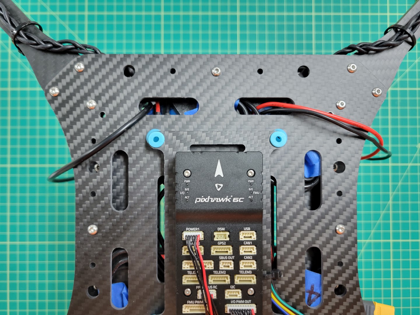
Top down view of power wires for VMC and PCC
11.3 - FC ⟷ VMC Telemetry Cable
Overview
It’s important that the FC and VMC can communicate with each other.
This bi-directional communication will allow us to receive telemetry
data from the FC and send data to it from the VMC. If you recall,
before we communicated with the FC using a micro-USB cable connected to a
PC running QGroundControl. What you will be able to do now is communicate over a
WiFi network, which will make this process easier.
In addition to a wireless link between the AVR drone and QGC you will learn
how to configure position hold capabilities using external cameras. You may
have noticed with the basic drone that the drone required constant input from the
pilot to maintain position in stabilized flight mode. With the assistance
of these cameras you will be able to hover in position mode with ease!
The cable we build in this section makes this all possible.
Locate the following components in the photo below:
- 6 pin cable from the Pixhawk box
- 40 pin connector housing
- 3 female to female wires (black, purple, and grey)
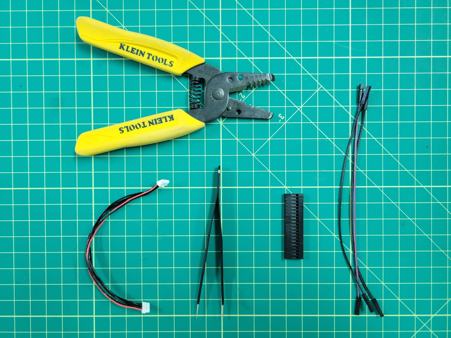
Necessary components for telemetry cable
Creating the Cable
Before we start building the telemetry cable let’s take a quick look at the following wiring diagram. The middle area represents the 40 pin connector housing. Pay attention to the pinout from the connector housing to the TELEM1 port on the Pixhawk FC. We will be using the following pins:
- Pin 2 - TX - Grey
- Pin 3 - RX - Purple
- Pin 6 - GND - Black
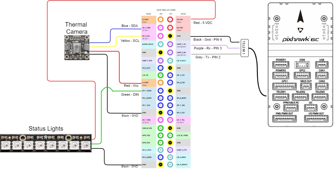
VMC pinout
Using tweezers you will remove pins 1, 4, and 5 from the Pixhawk connector. This is done by prying the plastic tab for each pin as shown in the photo below.
Removing pin 1 from the telemetry connector
The photo below shows only the necessary pins remaining: pin 2, 3, and 6 from left to right.
Telemetry wires: TX, RX, and GND
Clip the connector from the other end of the Pixhawk cable. Cut all three of the individual female-female wires to approximately 2-3". Strip 1/2" of shielding away from all wires as shown in the photo below.
Wire prep for soldering
Prior to soldering make sure each colored wire matches the corresponding pin. The photo below shows one final check before soldering.
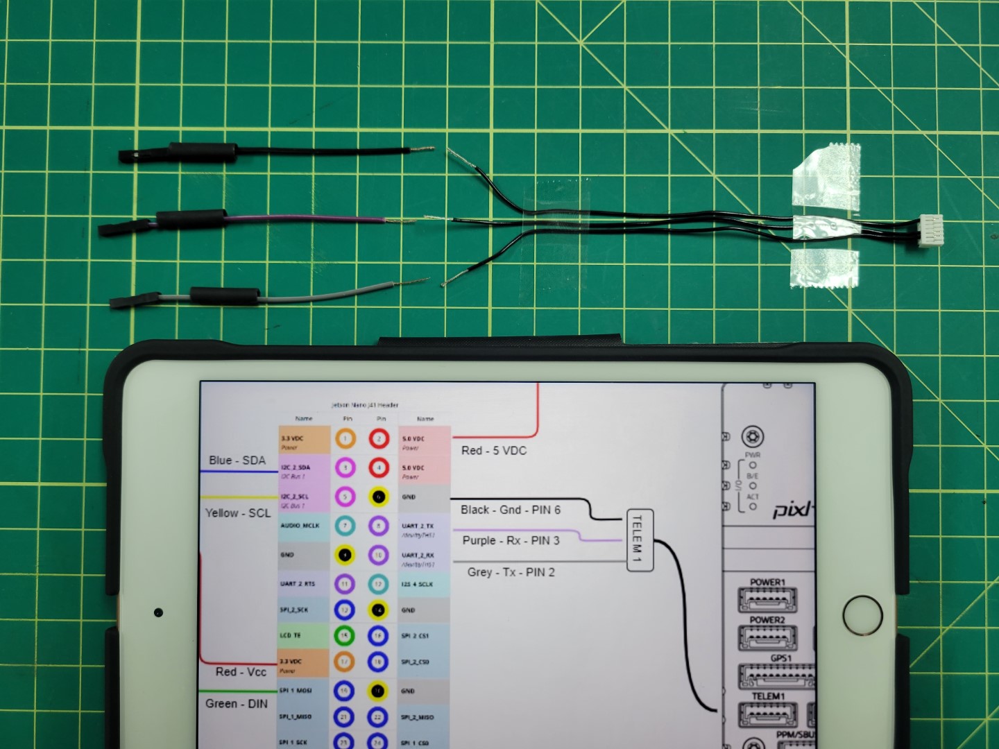
Confirming layout before soldering
Join the wires using the “Twisted Helix” method we covered in the ESC wiring during basic assembly.
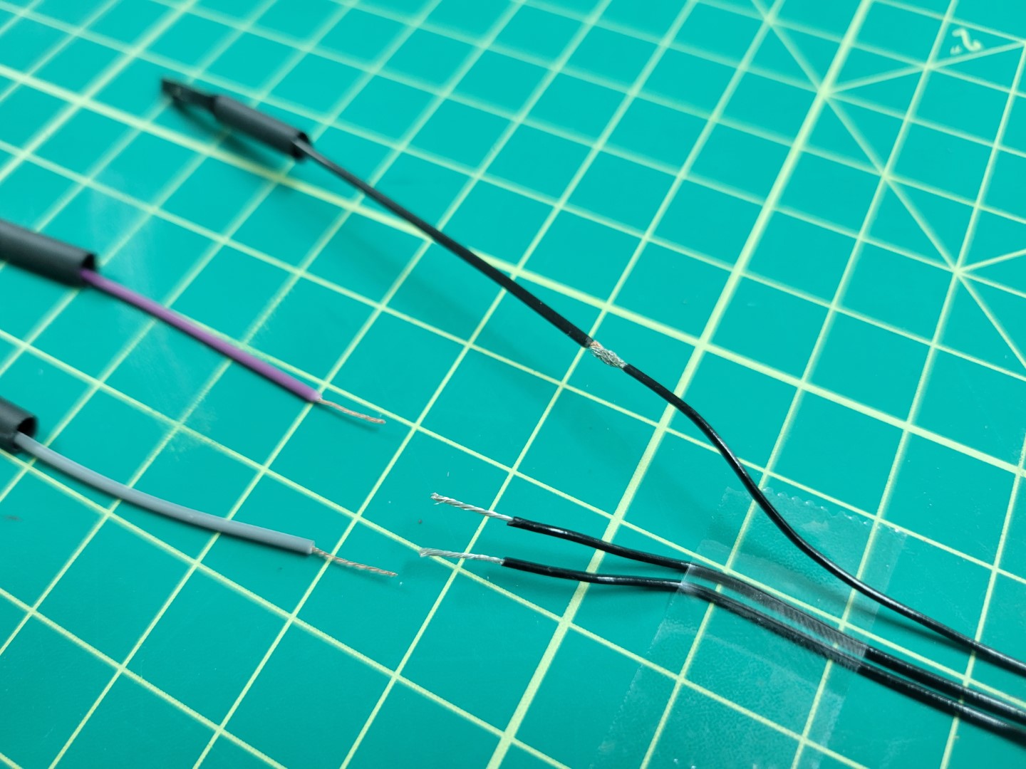
Joining wires prior to soldering
Solder all three wires and apply heat shrink.
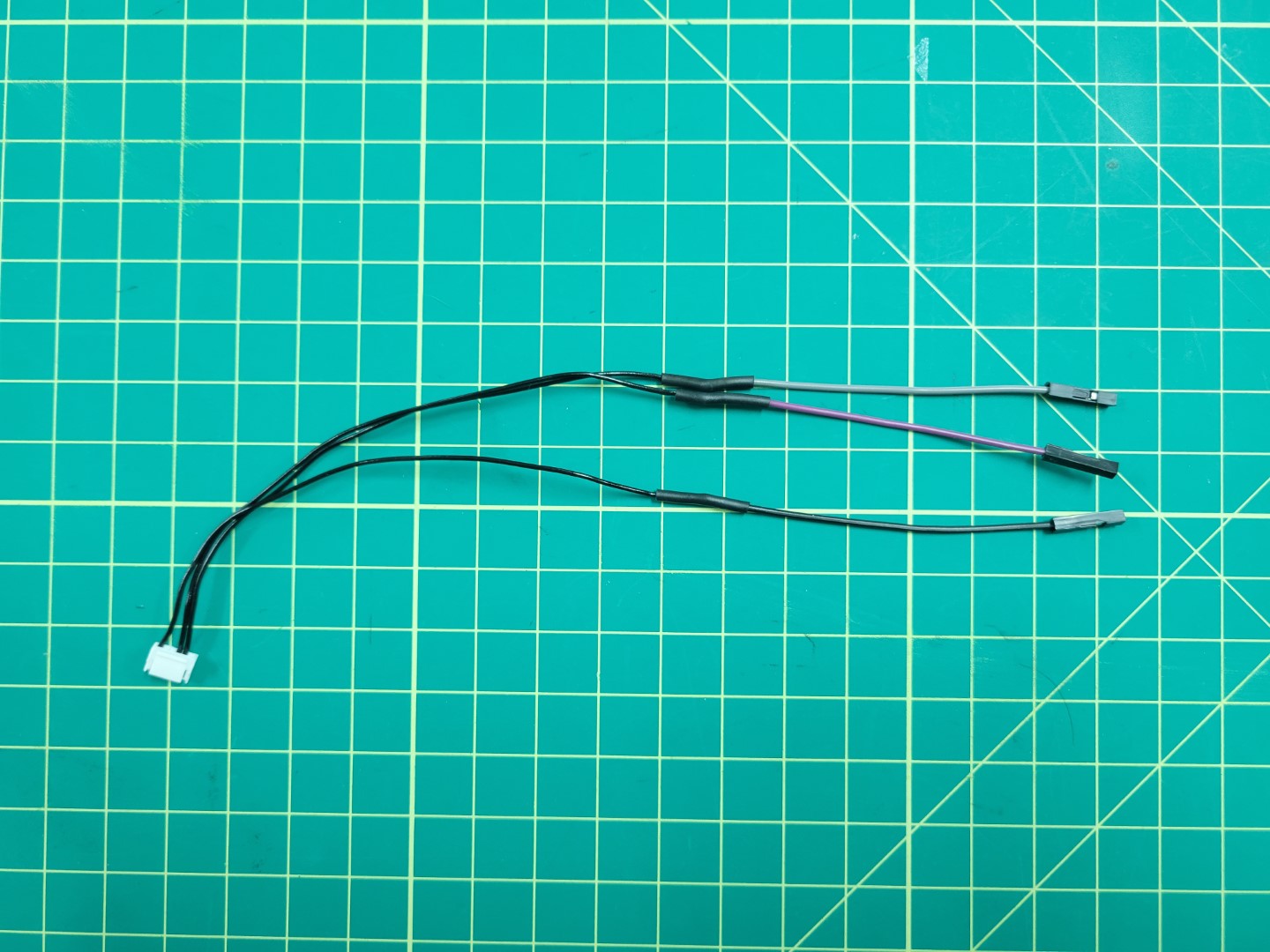
Telemetry cable with all three wires soldered
Remove the plastic connectors from the grey, purple, and black wires.
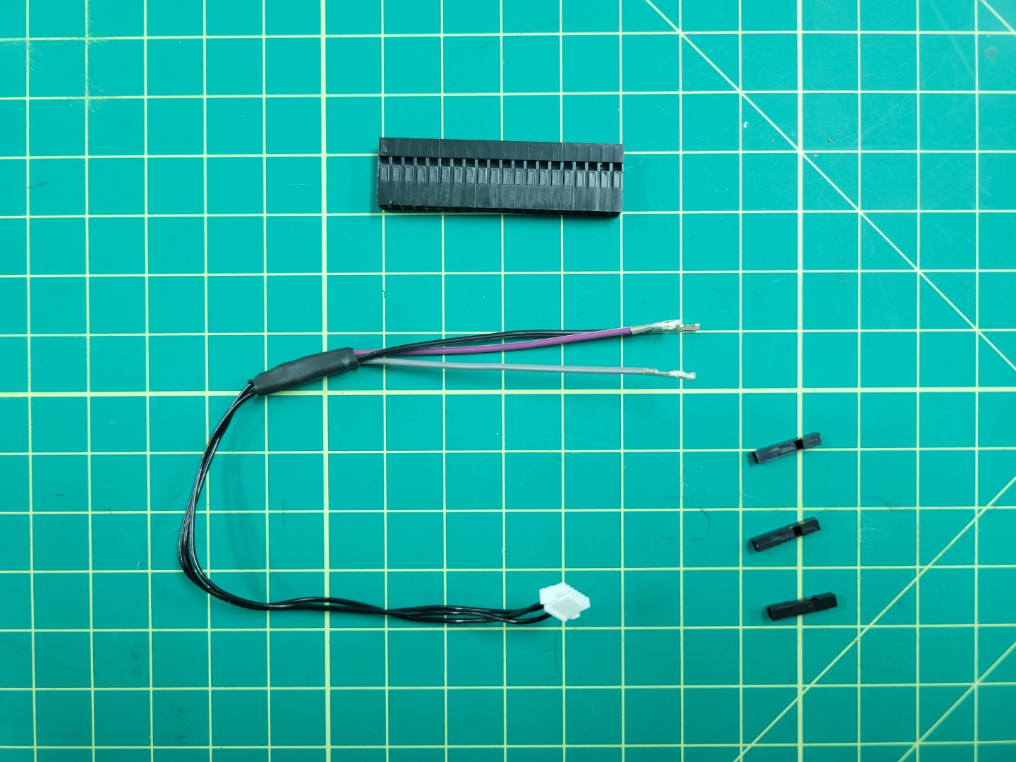
Plastic connectors removed
Insert all three wires into the 40 pin connector housing as shown in the following photos. If you’re uncertain where to insert the wires refer back to the diagram in the overview section.
Make sure you hear each of the pins click into the connector housing. Inserting them properly into the housing will prevent them from accidentally getting pulled out.
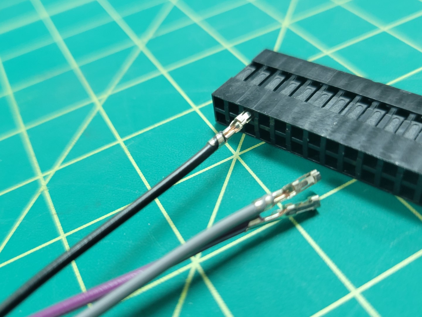
Adding telemetry wires to 40 pin connector
Now that your telemetry cable is complete you can do a test fit. Pay attention to the orientation of the 40 pin connector as seen in the photo below.
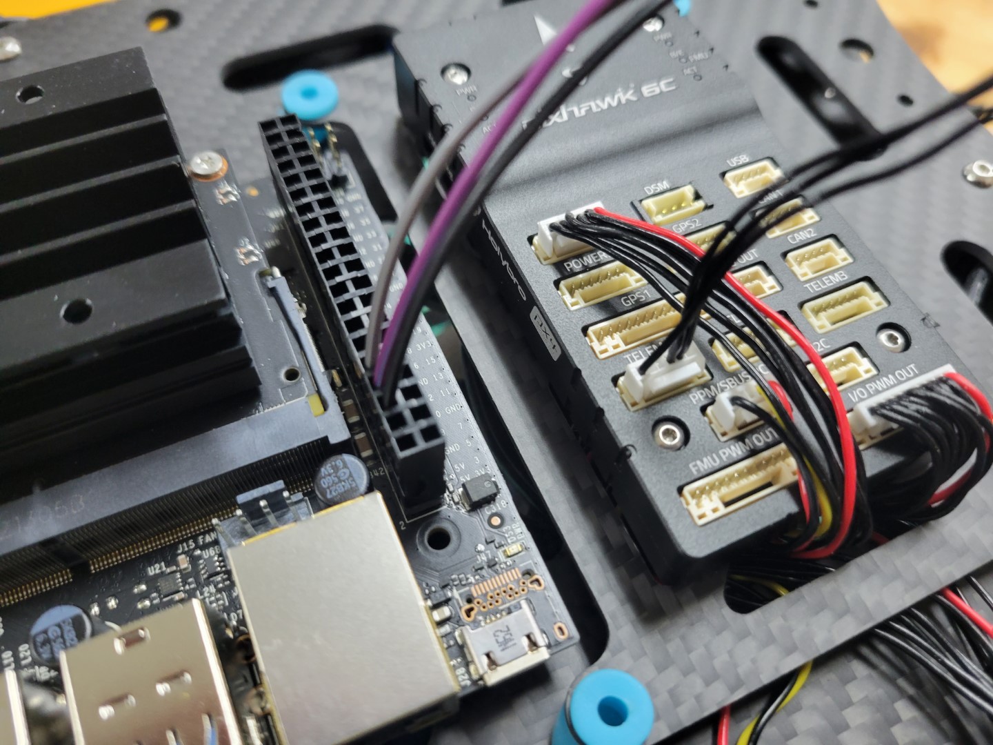
Telemetry cable connected to VMC and Pixhawk TELEM1 port
11.4 - Top Accessory Plate Assembly
Overview
In this section we will cover mounting the VMC and PCC to the top accessory plate followed by attaching the plate over the FC. Locate the ziploc bag of 2.5mm nylon hardware. We will be using the 6mm nylon standoffs, bolts, and nuts. Make note of the four holes around the larger cutout on the left. This is where we will mount the VMC. In addition, make note of the four holes around the smaller cutout on the right. This is where we will mount the PCC.
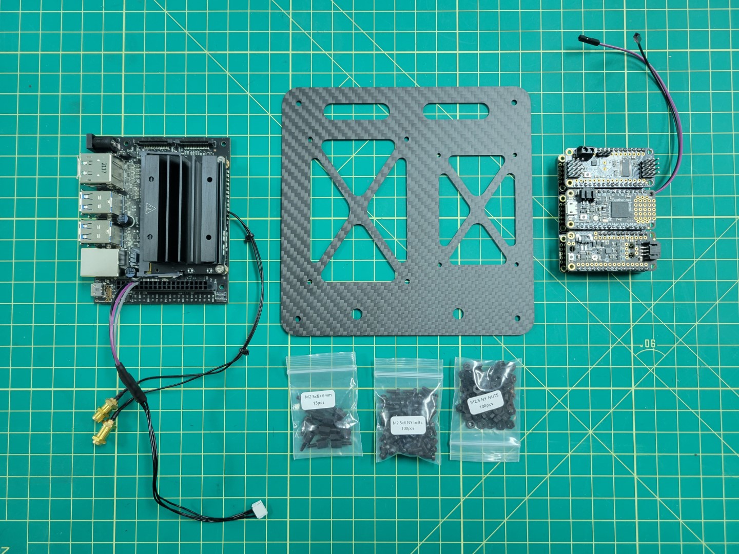
VMC, PCC, top assembly plate, and nylon hardware
Start by placing the 6mm standoffs facing down through the mounting holes in the top plate. Use a 2.5mm nut to secure each of the standoffs.
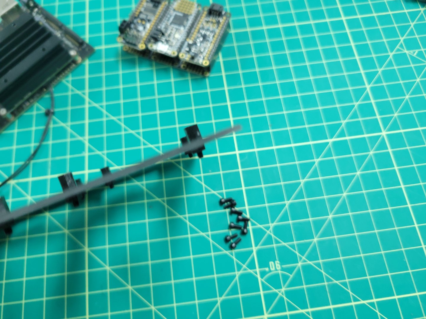
Installing 6mm standoffs
The photo below shows the completed standoff installation.
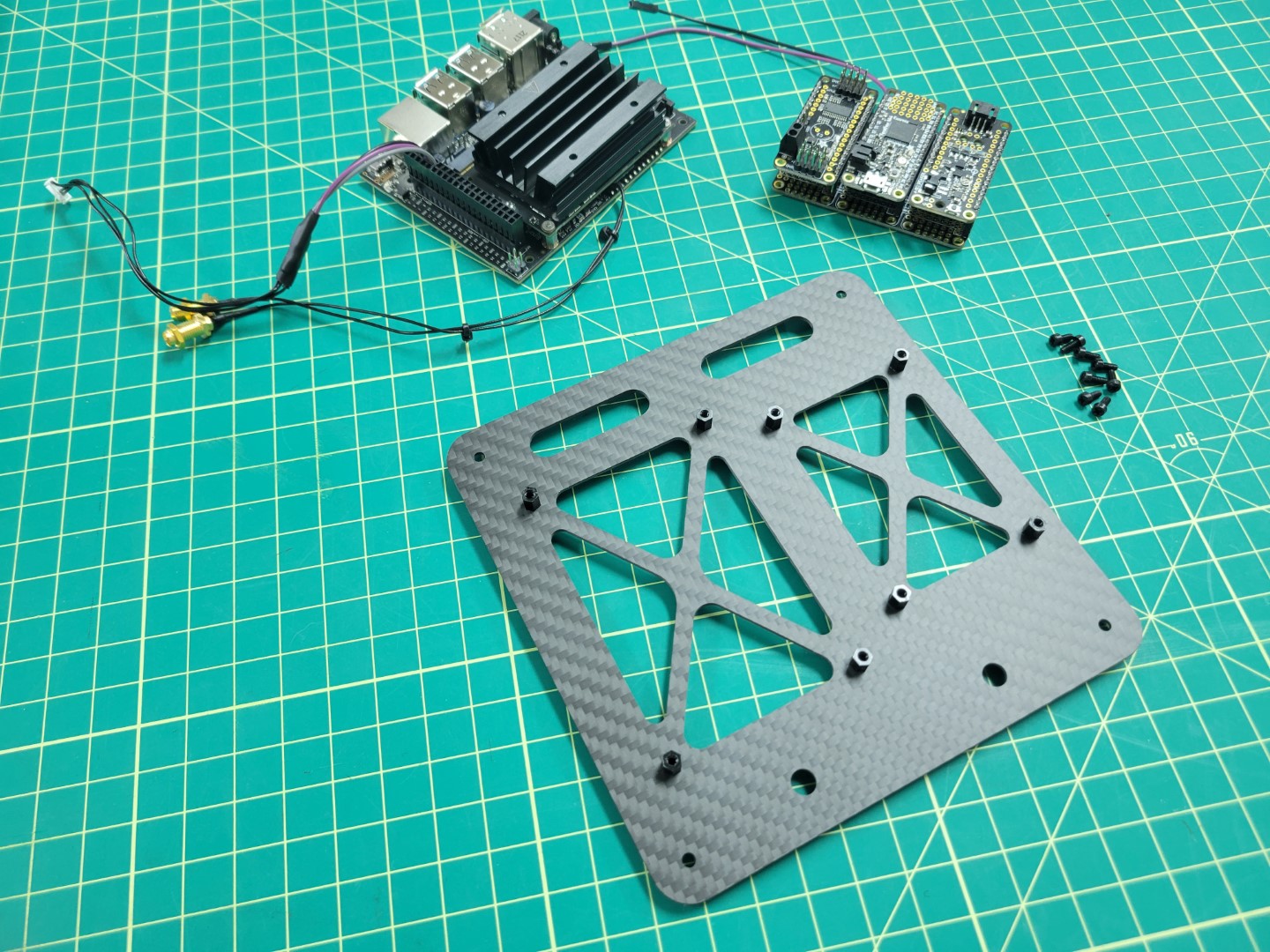
6mm standoffs in place for VMC and PCC mounting
VMC Mounting
We will now mount the VMC to the top accessory plate. The VMC is the “brains” behind your AVR drone build and will be responsible for running the Bell software stack during testing and on competition day.
With the standoffs secured into the top accessory plate the next step is to attach the VMC. These standoffs will provide enough clearance for the VMC so that the solder joints beneath do not make contact with the carbon fiber plate. Carbon fiber is conductive, which means that it can cause your board to short out if two leads touch the plate.
Align all four of the VMC mounting holes over the 6mm standoffs and secure into place with the nylon bolts. The VMC will be mounted on the left of the top accessory plate with the USB ports facing out.
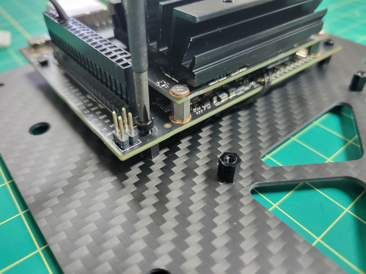
Securing nylon bolts for VMC mounting
The orientation of your top plate and VMC should look identical to the photo below.
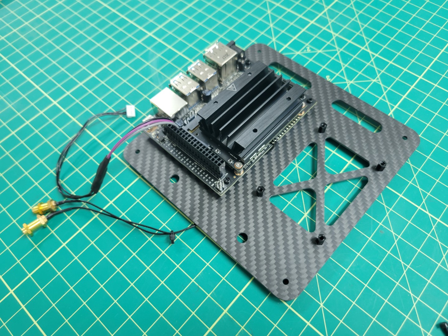
VMC mounted to top accessory plate
VMC Cooling Fan
During advanced testing you will be running the AVR software stack on your VMC.
Since we make extensive use of the VMC’s CPU and GPU it can heat up significantly.
It’s important to keep your VMC cool and in this section you will install a cooling
fan onto the top of the VMC heat sink.
There are two nuts and bolts included in a small ziploc bag with your cooling fan. Place your cooling fan on top of the heat sink and insert two bolts, on opposite corners, through the fan and the heat sink.
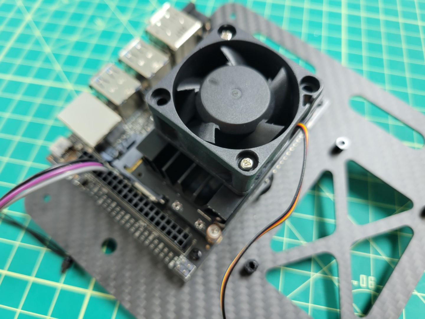
Cooling fan with bolts on opposite corners
Note
The nuts provided with the cooling fan are not self-locking.
It’s a good idea to use a small amount of Loctite to keep them secure.
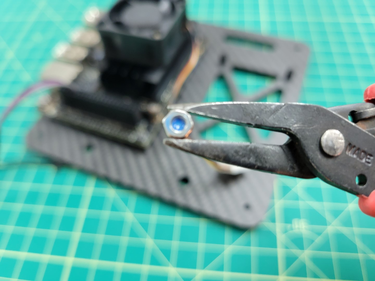
A small drop of Loctite applied to cooling fan nut
Use needle nose pliers to hold the nut in place and screw the bolt from the top using a Phillips head screwdriver.
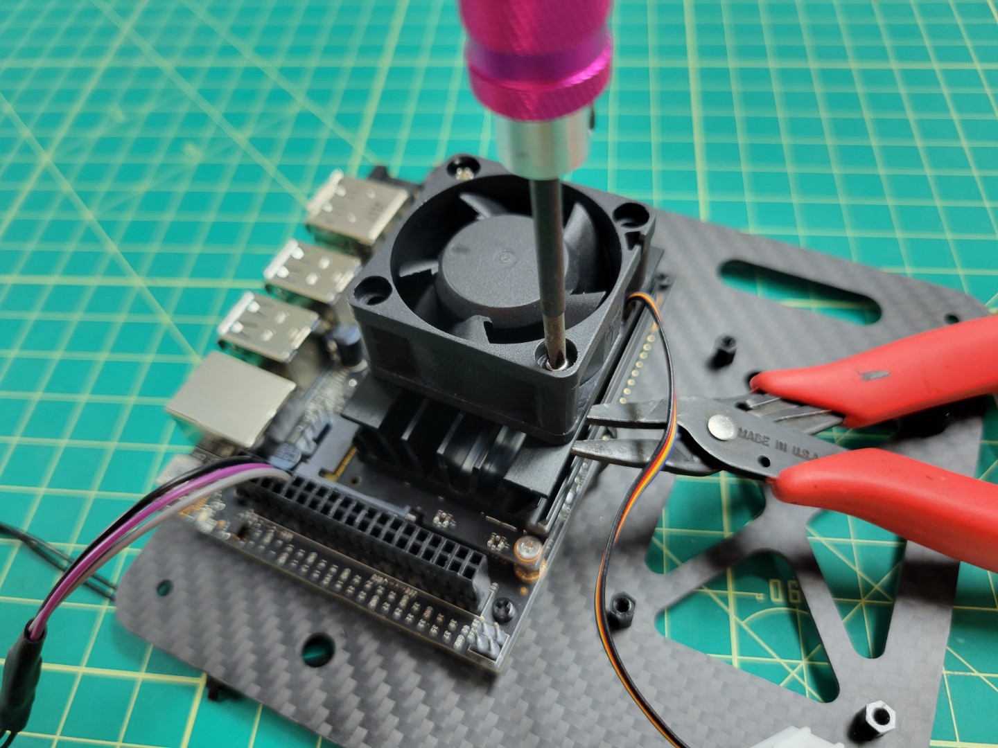
Securing the cooling fan with screwdriver and pliers
Repeat the process for the other nut and bolt. Attach the fan’s power cable to the VMC as shown in the photo below.
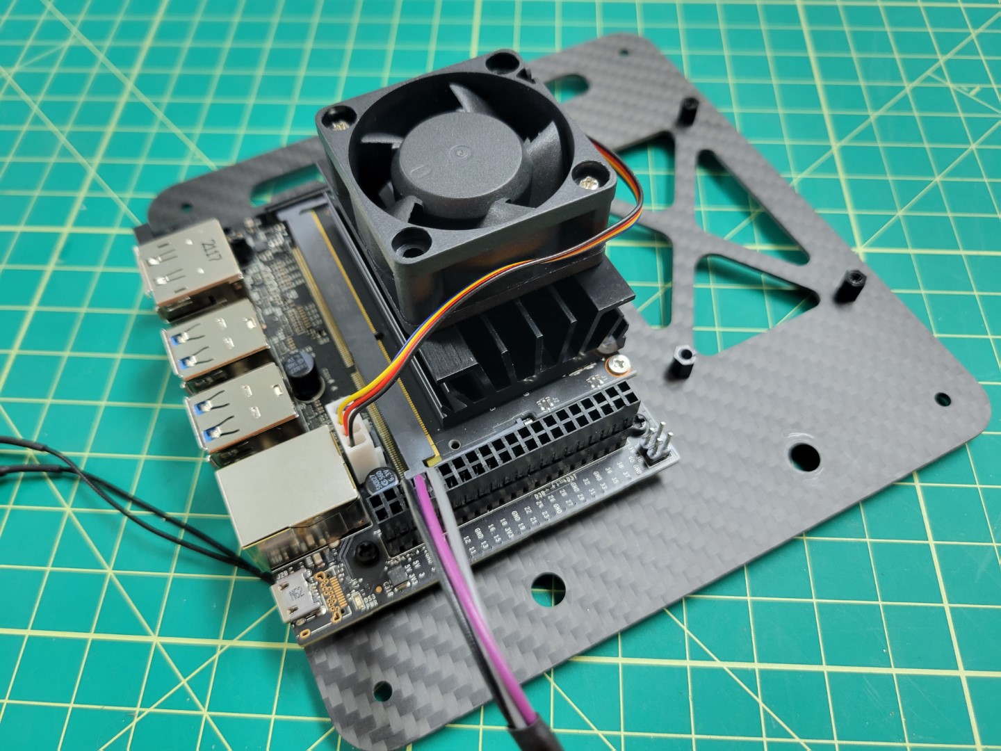
Cooling fan connected to power port
Note
The cooling fan automatically turns on to 100% when the VMC is powered on.
This functionality was installed as part of the AVR software, and helps
keep the VMC cool.
PCC Mounting
Let’s proceed with mounting the PCC to the top accessory plate. Make note of the photo below and that the micro USB port is facing outward.
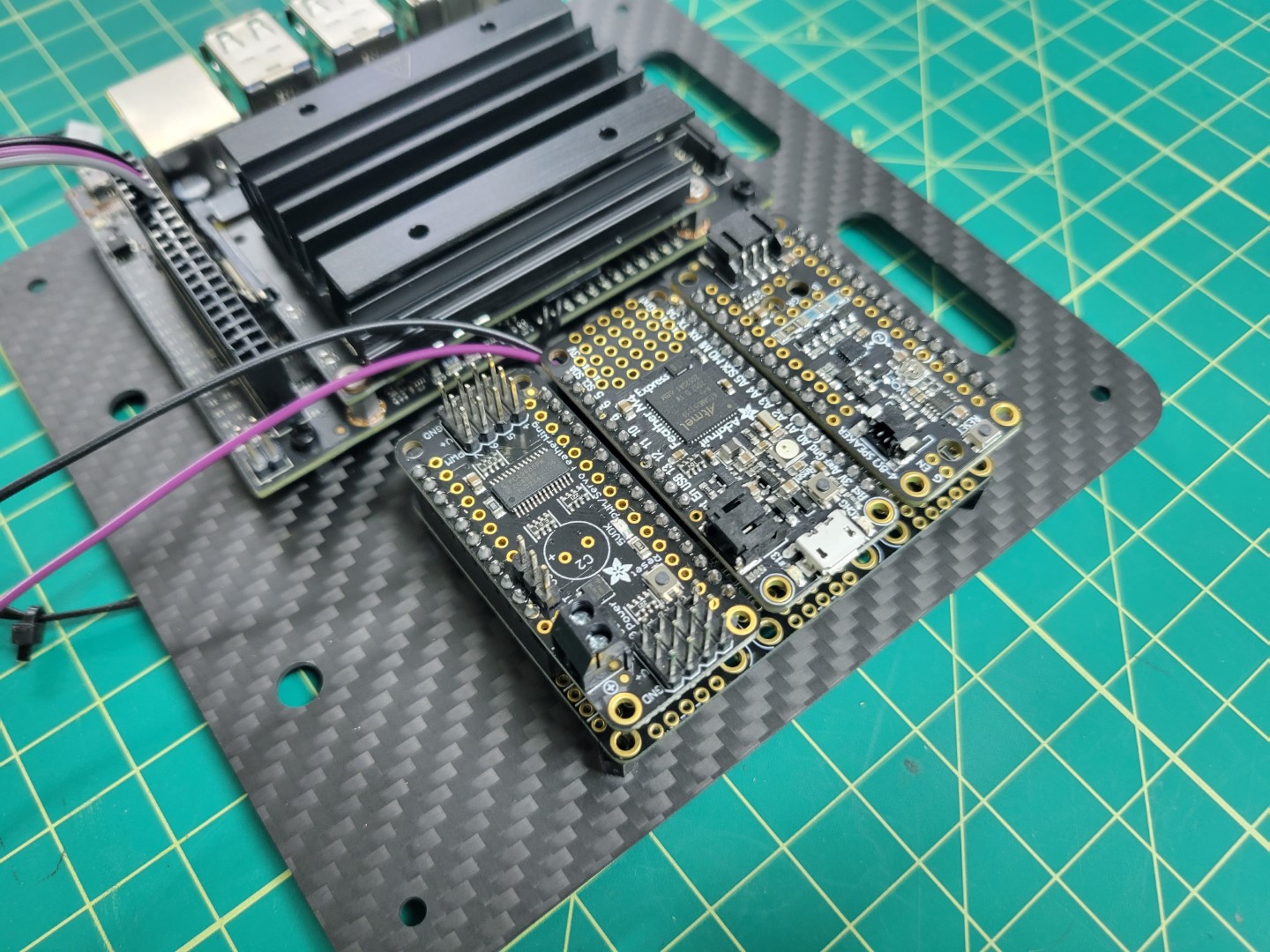
PCC USB port must face outward
We will secure the PCC with four nylon bolts. The easiest way to do this is to remove the top and bottom PCC boards as shown in the photo below.
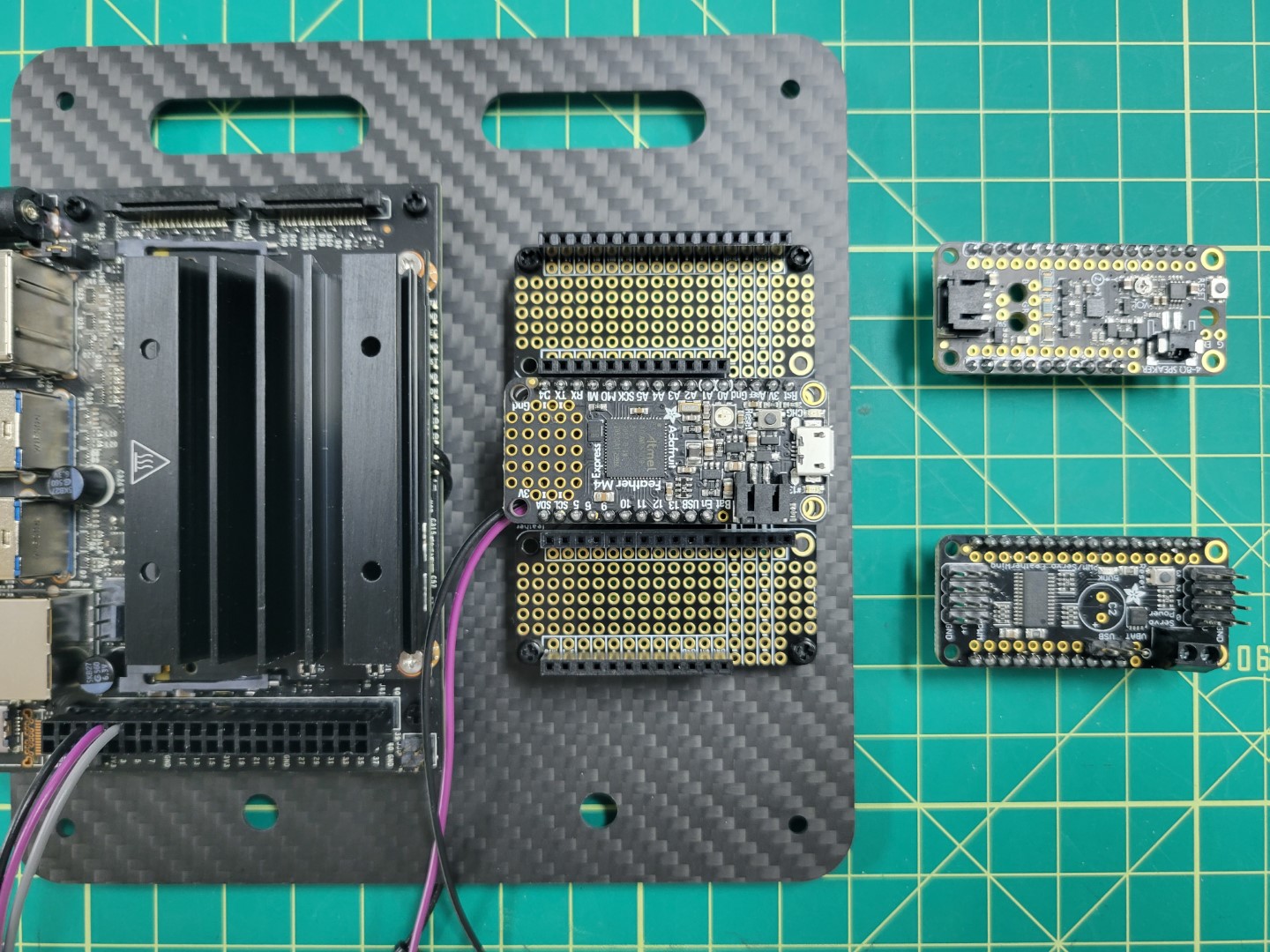
Securing PCC with four nylon bolts
Replace the boards back into the PCC and mounting is complete!
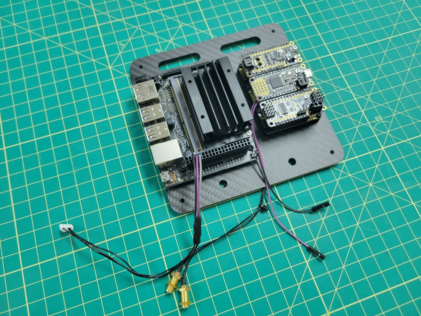
PCC mounting complete
Top Accessory Plate Mounting
Before we can place the top accessory plate onto the drone we must screw the antenna connectors into place.
Run the VMC and PCC cables through the bottom of the plate as shown in the photo below.
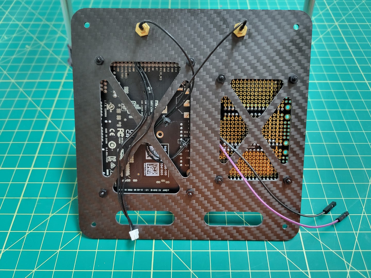
Cable management for top accessory plate
With the VMC and PCC attached to the top accessory plate and wires routed let’s proceed
with mounting the plate over the FC using 40mm standoffs and 10mm M3 screws.
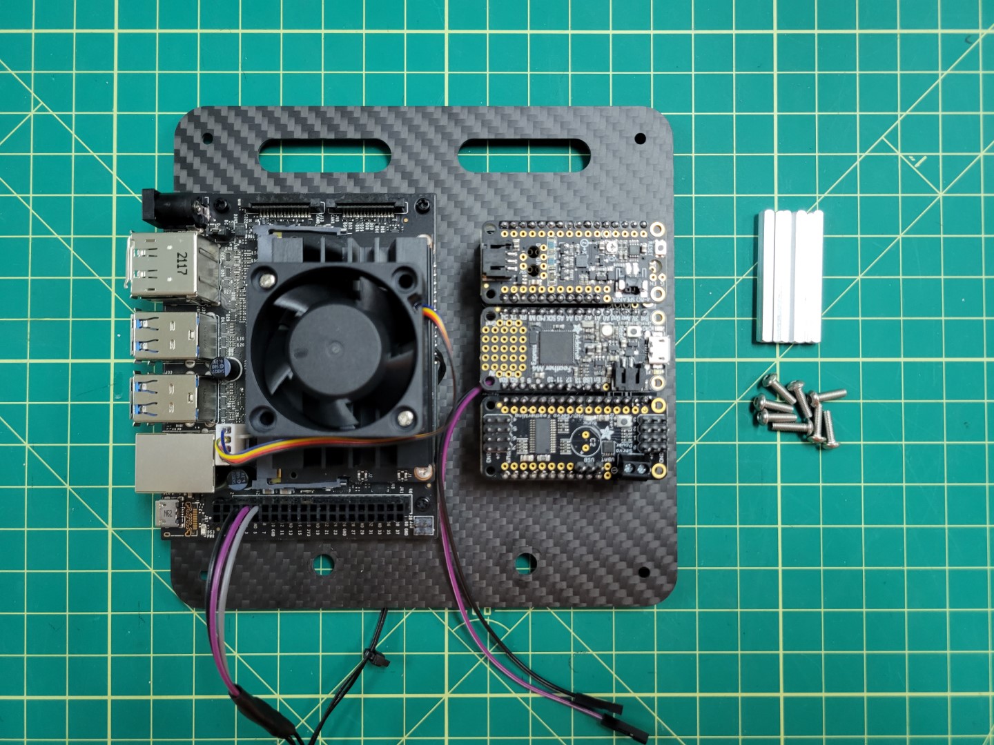
Hardware for accessory plate mounting
Place blue Loctite on one of the 10mm screws.
10mm mounting screw with Loctite
There are four access holes in each corner of the bottom mid-plate, close to where you mounted the 3D printed landing gear.
Use a long hex driver to feed the screw up through the bottom accessory plate and through the mid-plate assembly.
Feeding screw through bottom mid-plate
Another option is to use a short L-shaped hex key to feed the screw into the hole.
Using hex key to feed screw through bottom mid-plate
Hand tighten the 40mm standoff onto the screw.
Placing 40mm onto 10mm screw
Securely fasten the standoff and repeat the process for the other three standoffs.
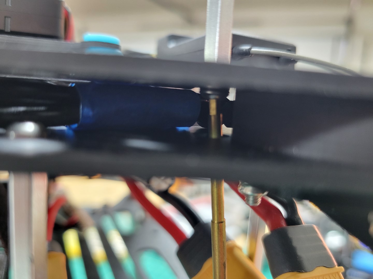
Top accessory plate standoff securely fastened
Connect the telemetry cable from the VMC to the TELEM1 port on the FC.
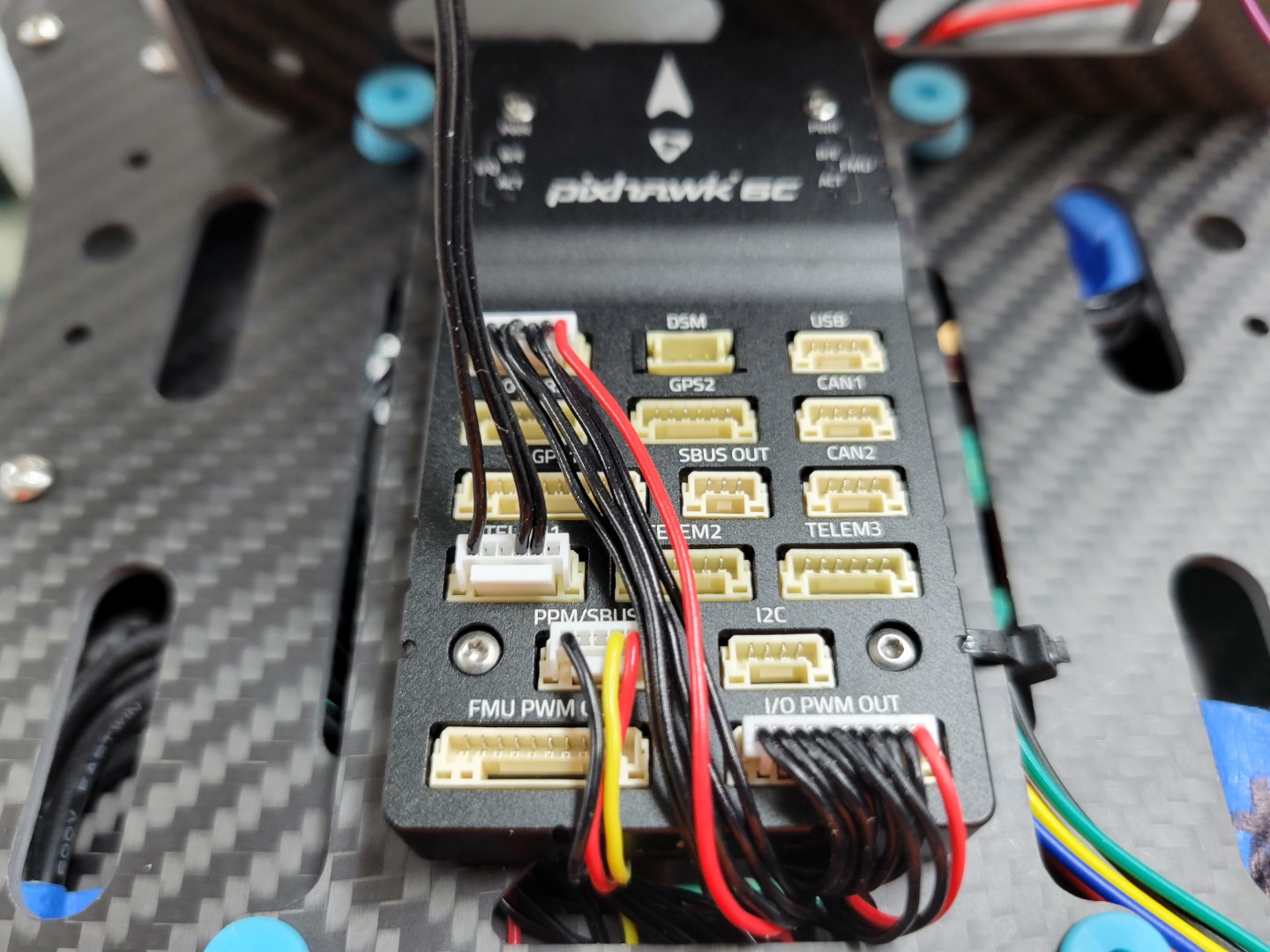
Telemetry cable connected to TELEM1 on FC
Use four 10mm screws to mount the top accessory plate onto the standoffs. Do not forget to use blue Loctite on each of the screws.
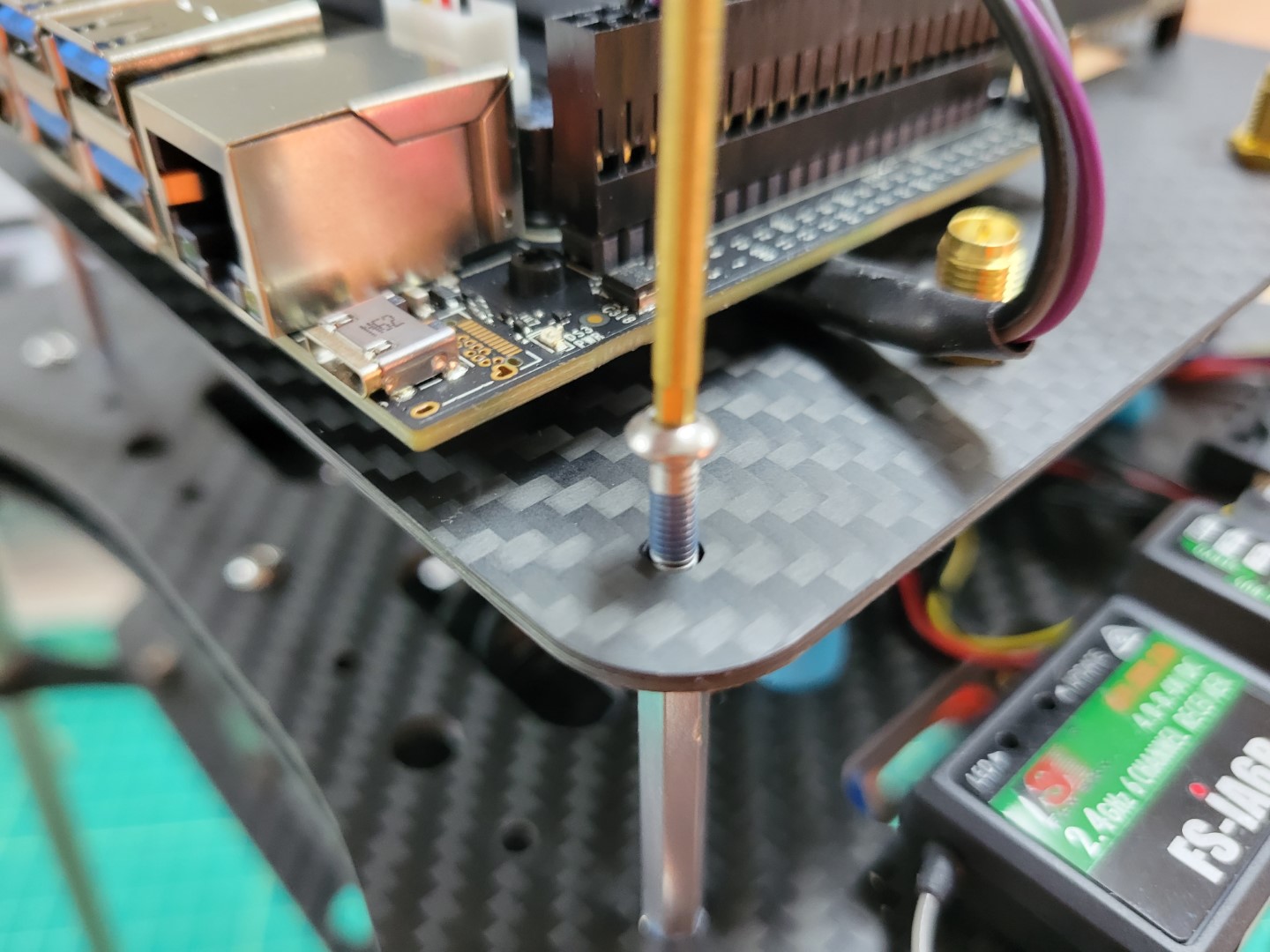
Securing top accessory plate on standoffs
Note
Make sure the top accessory plate is mounted with the VMC on the left and PCC on the right as you’re standing behind the AVR frame.
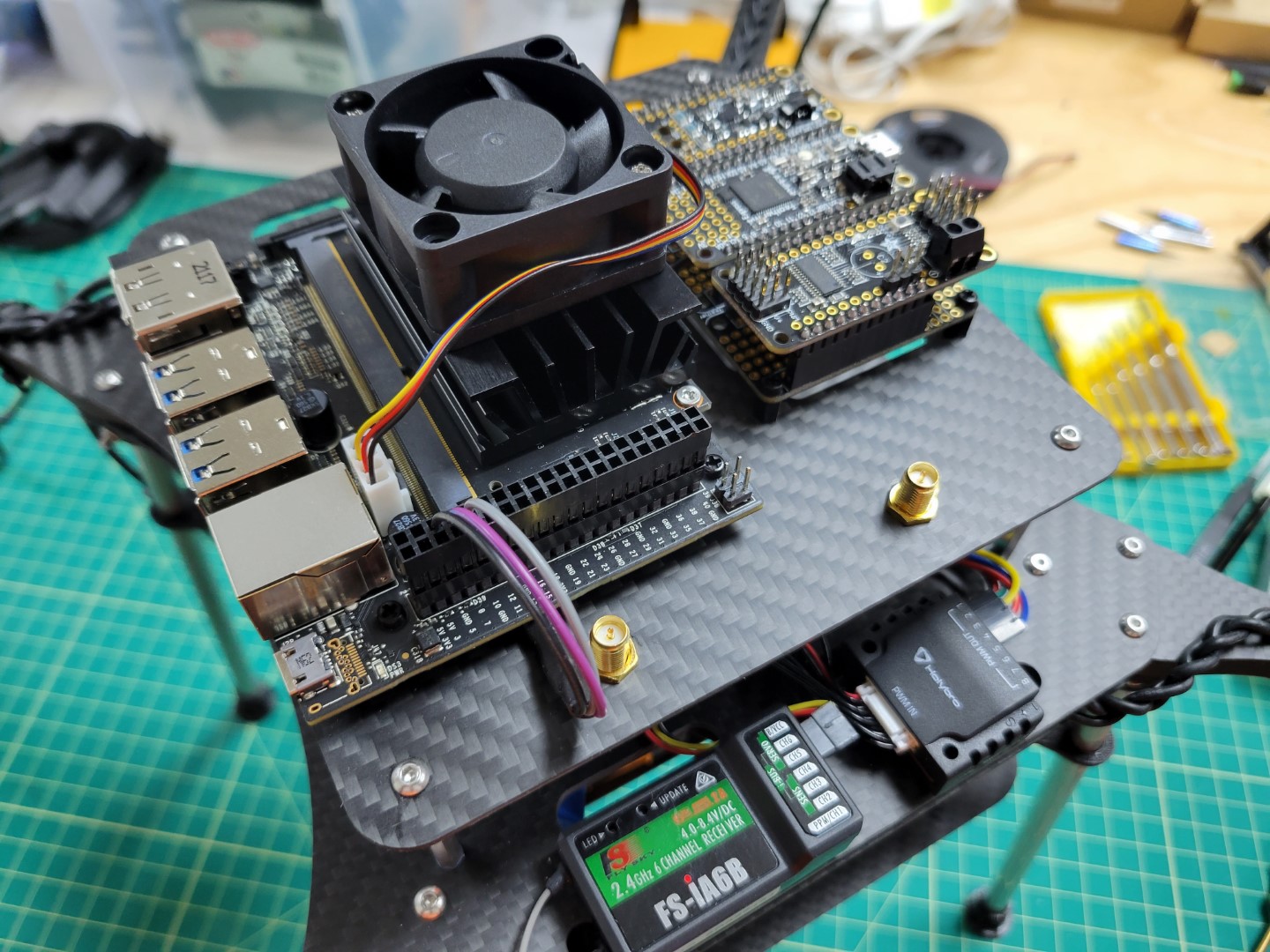
Top accessory plate secured
Wiring
Connect the barrel plug from the VMC buck converter to the VMC power input.
Note
Make note of the jumper in the photo below.
The jumper must be in place for the VMC to be powered using the barrel jack.
If you need to revert to power over the micro USB port you can move the jumper so that it’s only connected to a single pin.
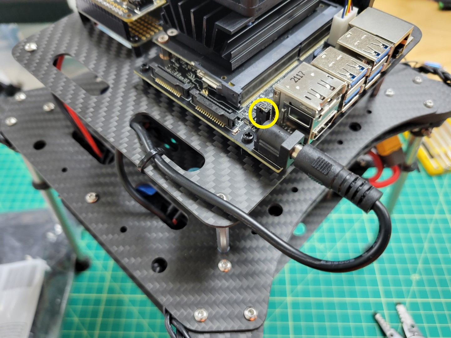
VMC ready to be powered with the barrel plug
Finally, cut the positive and negative wires from the PCC buck converter to length.
Trim 1/8" of shielding from the wires and connect them to the PCC power terminals as shown in the photo below.
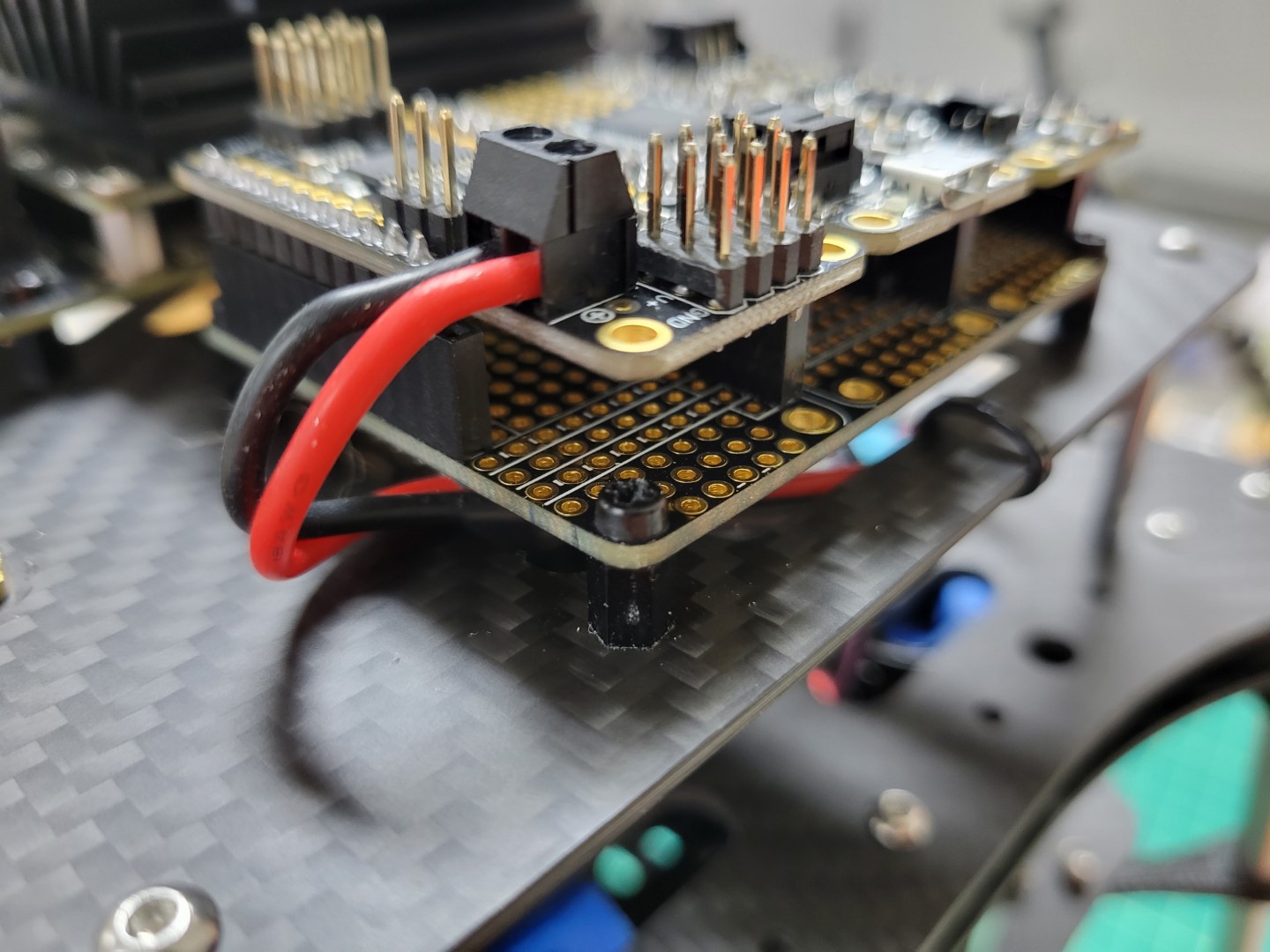
PCC power leads connected
11.5 - Zed Mini Camera Mounting
The ZED Mini will be mounted to the front of your AVR drone and connected with a USB-C
cable. This camera is instrumental in mapping out
the environment in real-time and providing location updates to the VMC.
This enables your AVR to “see” and maintain it’s current position without GPS!
You should have printed the
Zed Mini mount from the 3D Printing section
of this documentation. The ZED Mini should clip into your 3D printed mount securely.
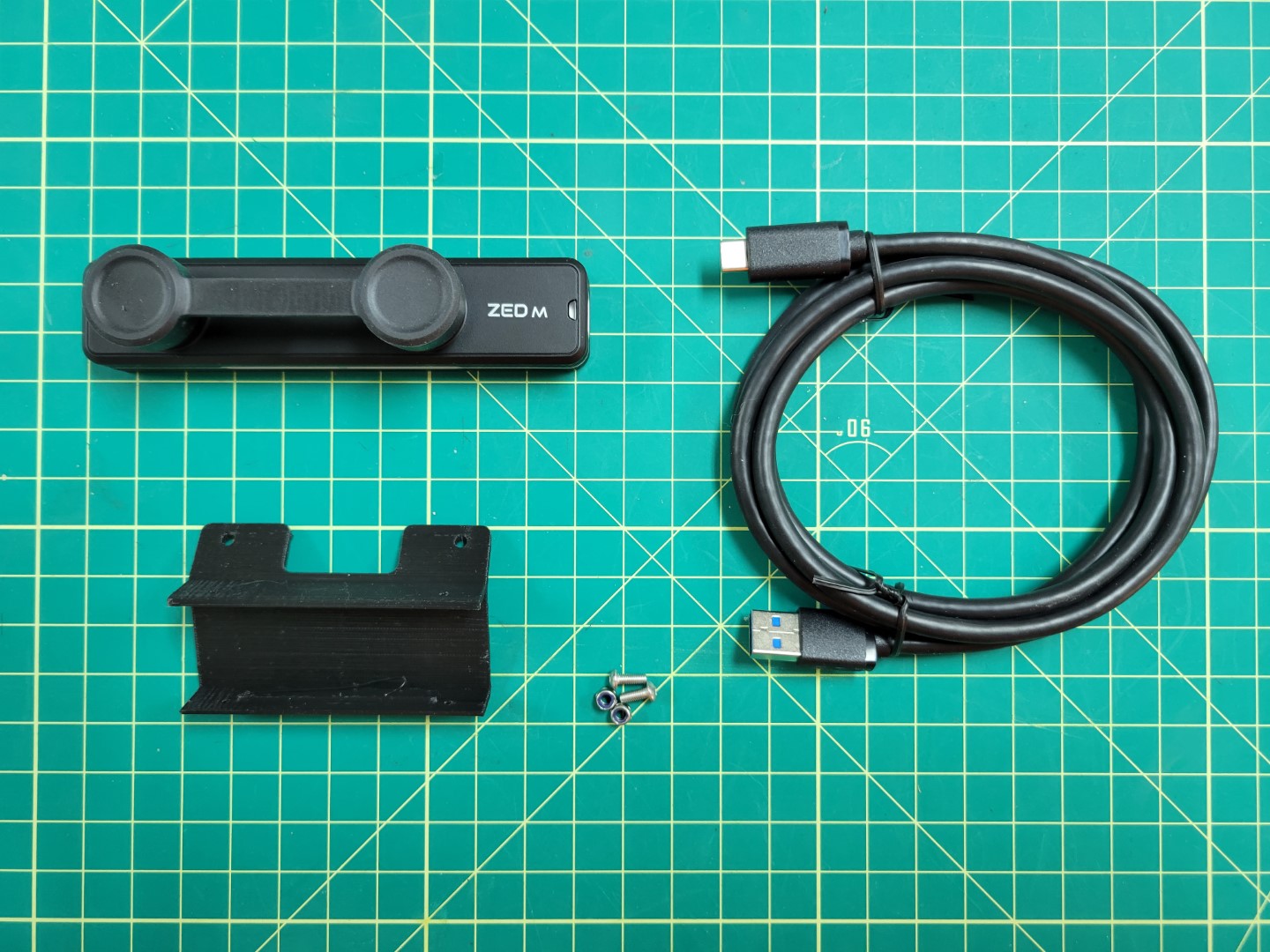
Hardware for mounting ZED Mini
Secure the camera mount to the bottom accessory plate with two M3 8mm screws and lock nuts.
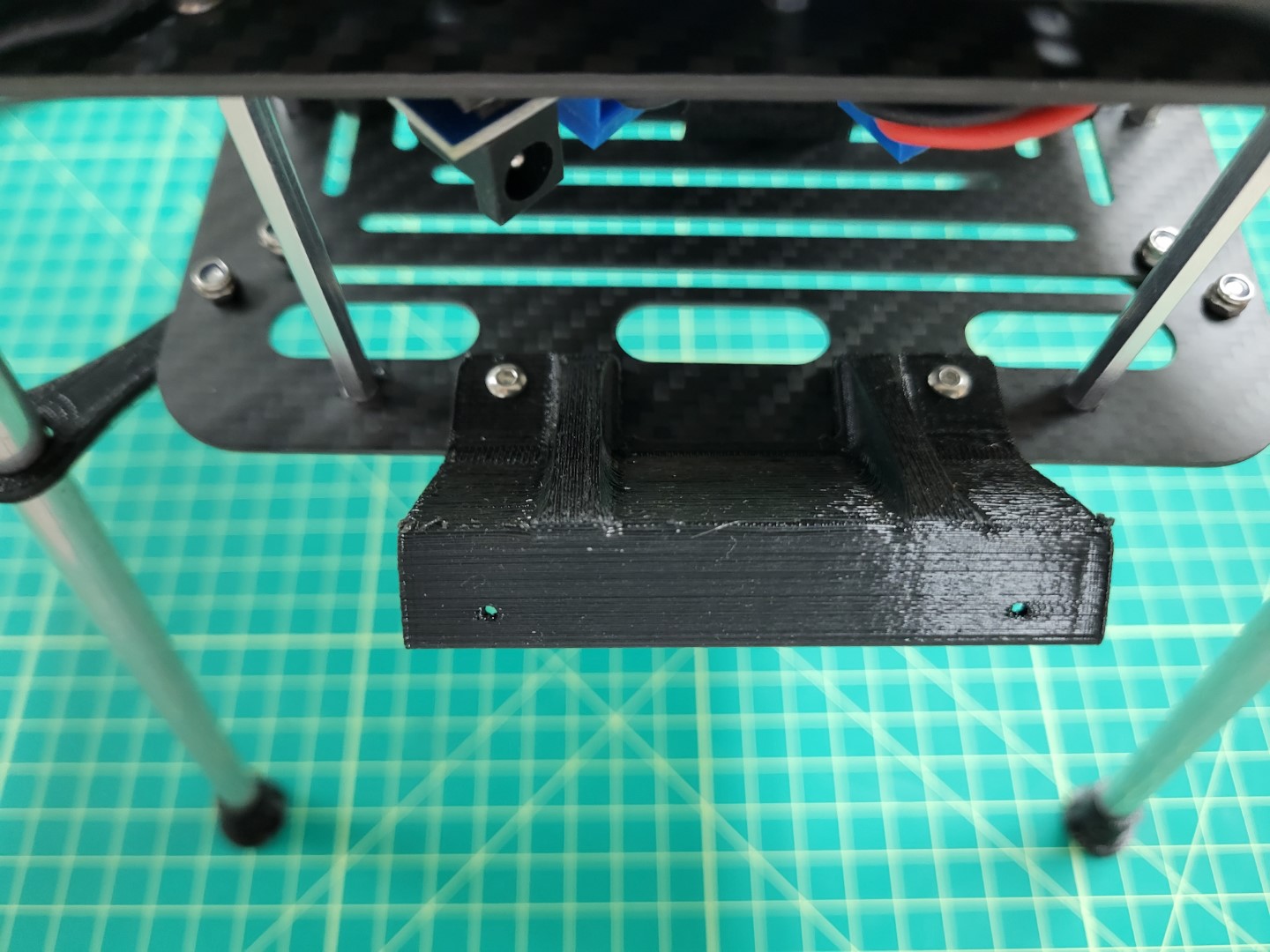
ZED Mini 3D printed camera mount
You will notice that the mount points 45 degrees downward. This aids in tracking both in front and beneath the AVR drone.
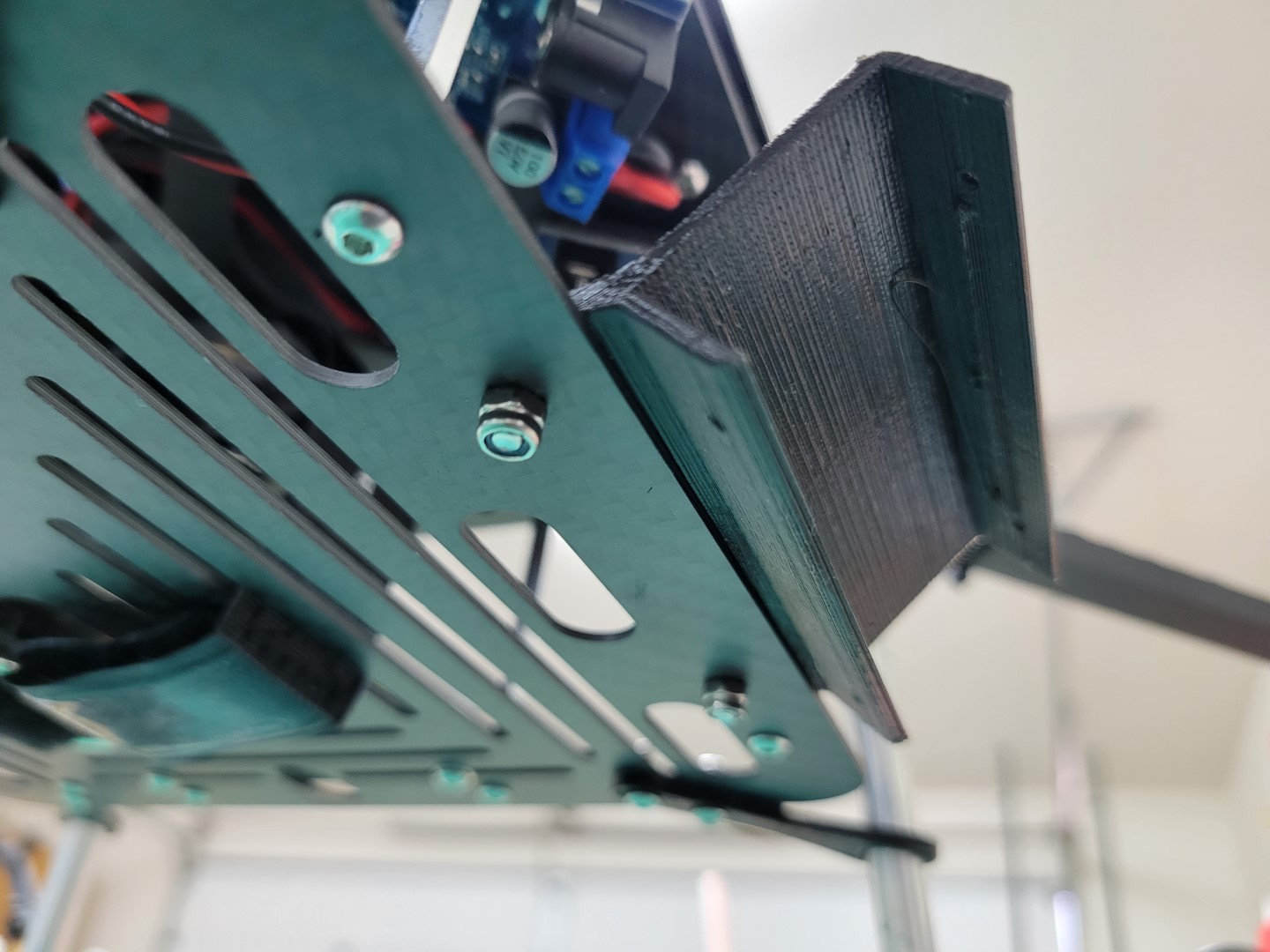
45 degree downward tilt
Snap the ZED Mini into the mount. Make sure that the ridges in the mount snap into the recessed areas on the top and bottom of the camera. You should not be able to slide the camera left and right when properly secured.
Warning
You will notice there is a bit of play when you wiggle the camera back and forth. This can cause problems for ZED Mini’s internal sensors. We will further secure the camera with set screws from the servo hardware.
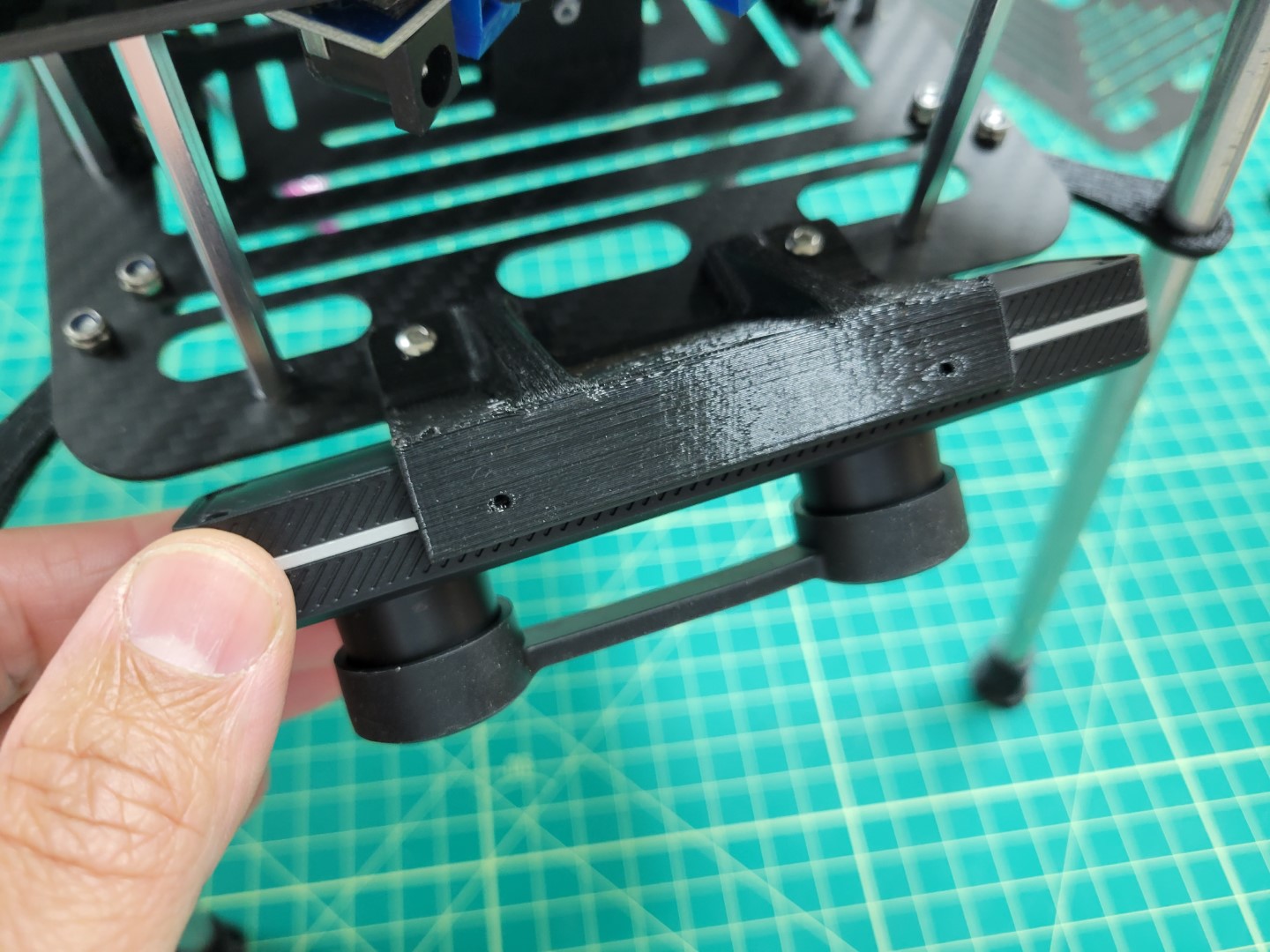
ZED Mini snapped into mount
Locate the large ziploc bag inside the AVR Drone Peripherals box. Inside this bag there are several screws floating around. You will need two of them that look like the ones in the photo below.
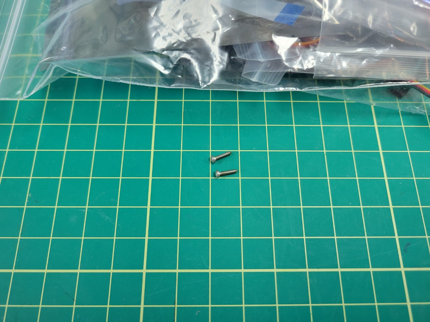
Set screws for securing ZED Mini into the mount
Use a Phillips head screwdriver to thread both screws into the 3D printed mount.
Note
The set screws will not go all the way in. Screw them until you make contact with the threaded hole in the ZED Mini. At this point you will feel a bit of resistance and can stop.
Wiggle the camera left and right to see if there is any play. If so, turn the set screws half a rotation. Repeat the process until the camera is fully secured.
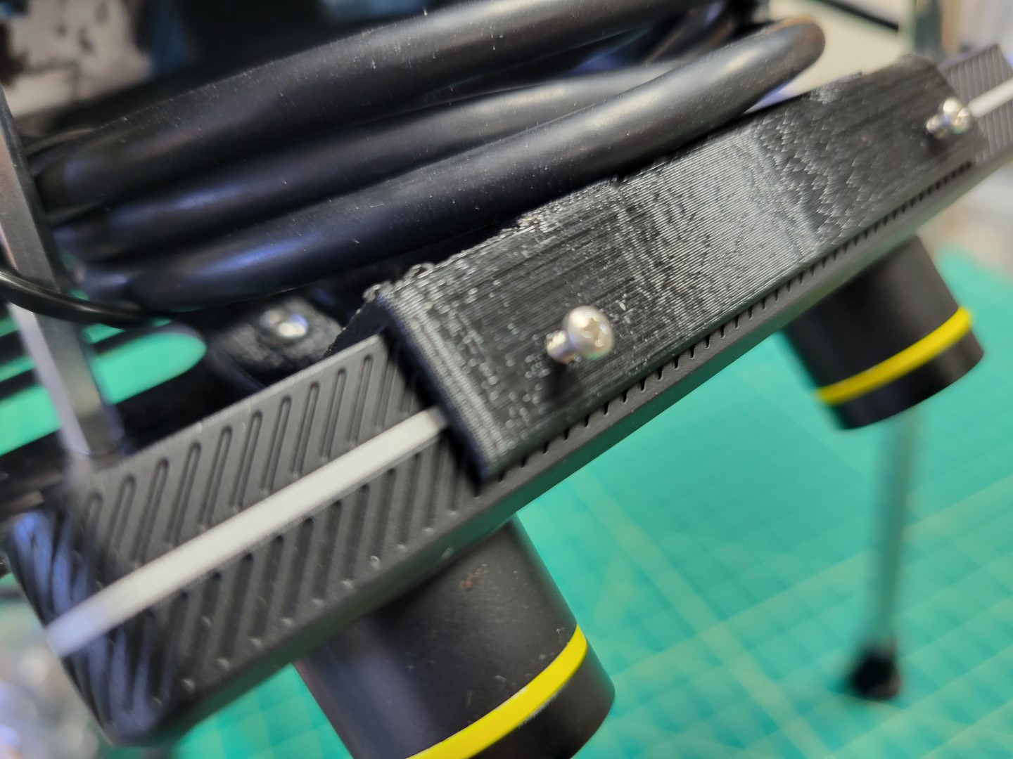
Set screws hold ZED Mini in place
Finally, you can plug the USB cable into the side of the Zed Mini
and into one of the ports on the VMC.
The Zed Mini has a unique USB-C cable so unfortunately it is going to be a little longer
than you need. We suggest rolling the cable up and tucking it between the bottom and
bottom-mid plate for cleanliness.
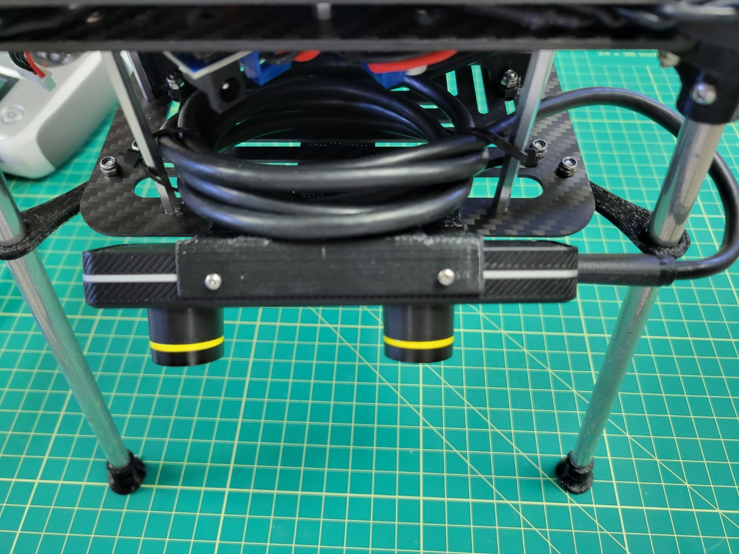
ZED Mini cable rolled out and zip-tied to standoffs
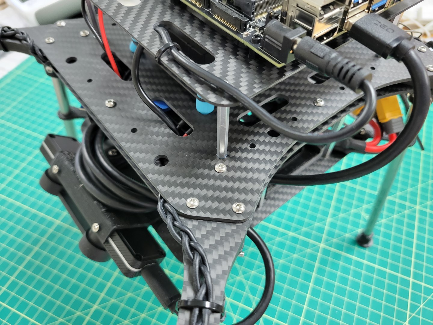
ZED Mini plugged into one of the VMC’s USB ports
Note
As you’re going through the build process make note of any cables that may
obstruct the drone’s propellers. The photos provided throughout this documentation
show how we’ve mounted things and provide a sufficient amount of clearance.
11.6 - Assembly Review
Great job! Please take a few minutes to watch the video below and
review all that we covered during the advanced hardware modifications.
12 - Checkpoint 2: Stabilized Flight Test
Please be sure to watch the video below to understand what to expect
from the advanced flight test. This will be done in stabilized
flight mode just like we did in the basic flight test.
13 - Software
13.1 - Flashing the SD Card
First, you need to download the Jetson’s operating system. A custom image with a baseline AVR software can be found here avr23.zip.
This is a large file, so it will take a while.
After the .zip file finishes downloading, extract this file, and plug in your
microSD card.
Windows
To flash the SD card on Windows, we recommend a tool called Rufus.
Go to this page and download
the rufus-<version>.exe file.
Download this installer file
Go ahead and launch Rufus.
When you launch the application, it should look something like this:
Rufus main window
- Make sure the correct device is selected. If your microSD card is not blank,
it will probably have a different label.
- Select the
.img file in the folder you extracted.
You will now be able to click the “START” button in Rufus. Go ahead and click this.
You will get a number of warnings that you’re about to format and wipe this
microSD card.
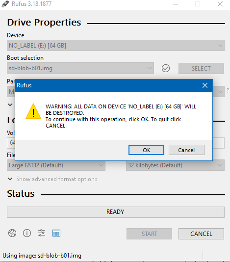
Rufus warnings
Go ahead and click through all of these, you know what you’re doing.
Rufus will begin flashing the microSD card and at the end will let you know
when it’s finished.
MacOS/Linux
To flash the SD card on MacOS or Linux, we recommend using Balena Etcher.
Go to their website and follow
the instructions to download and install Balena Etcher.
Go ahead and launch Balena Etcher.
Select the .img file in the folder you extracted, and select your microSD card.
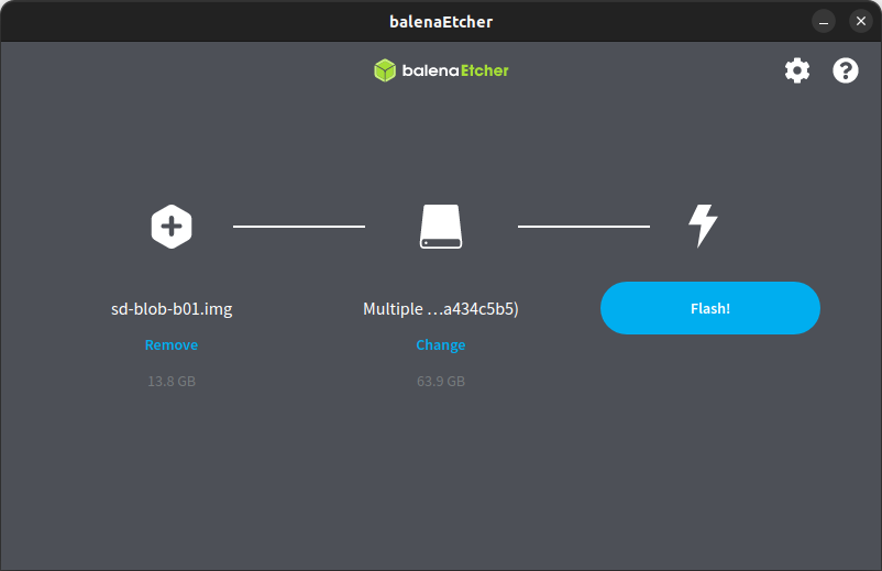
Options selected in Balena Etcher
Once you hit “Flash”, you may be prompted to enter your password
for super user privileges.
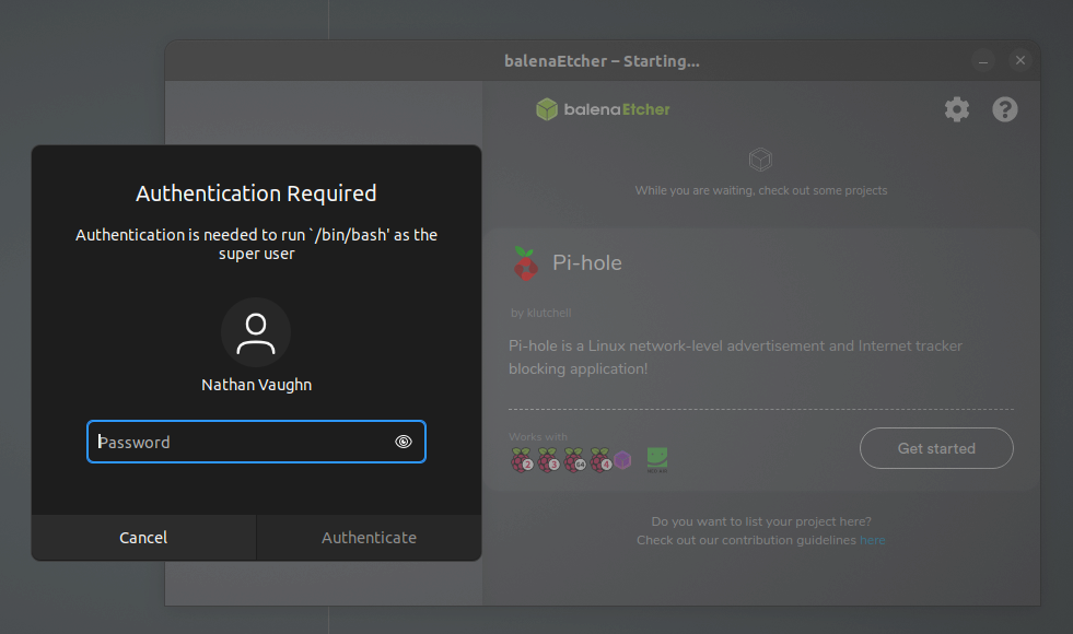
Enter your account credentials
Balena Etcher will begin flashing the microSD card and at the end will let you know
when it’s finished.
13.2 - Connecting to the Jetson
You’ll need to login to your Jetson many times to setup and run software.
Out of the box, your Jetson will have a default user account called
avr with a password of bellavr22.
Here are 3 possible methods you can use.
Monitor and Keyboard
Possibly the simplest way to connect to your Jetson is with
a monitor and keyboard. You’ll just need a monitor that has HDMI or DisplayPort
that you can plug in to the Jetson.
Once at the desktop,
you can open a terminal by clicking the application launcher
in the bottom left (the 9 squares) or with the keyboard shortcut
Ctrl+Alt+t.
Serial
If you do not have a monitor and keyboard, another method of logging in to your Jetson is over a serial connection.
To do this, you’ll need a serial client.
Installing Serial Client
Installing Serial Client on Windows
For Windows, we recommend PuTTy.
Go to this page
and download and install the putty-64bit-<version>-installer.msi file.
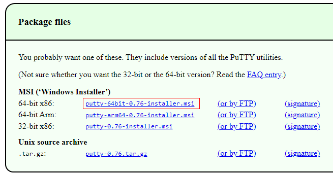
Download this installer file
Run through the setup wizard
Installing Serial Client on MacOS
Rather than using PuTTy, it’s much easier to open a terminal and simply run:
Installing Serial Client on Linux
You can follow the same steps as on MacOS
(after installing screen with sudo apt install screen),
but if you like a GUI, you can
install PuTTy with:
and launch PuTTy with:
Connecting to Jetson via Serial Client
Now, if you want to power the Jetson via USB (if the Jetson is not connected to
a wall adapter or a battery) remove the jumper behind the barrel jack.
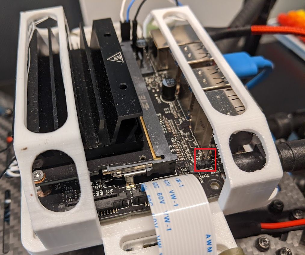
Tip
Keep this somewhere safe, like sticking it to a piece of tape, it’s very easy to lose!
Plug in a MicroUSB cable to the Jetson,
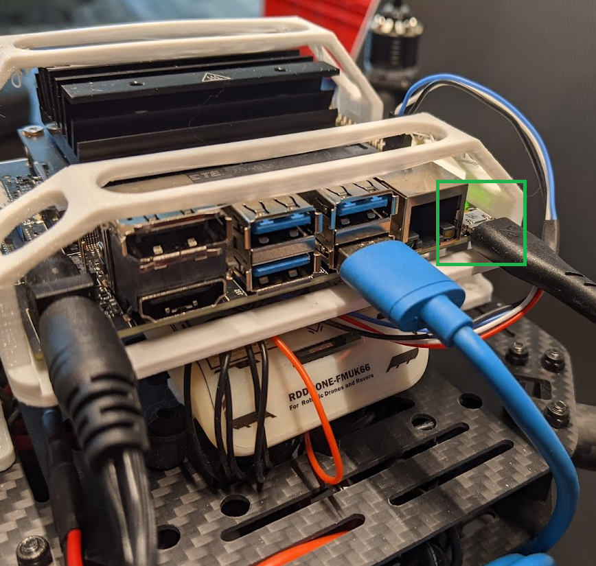
and then into your computer.
Tip
For Windows, open up Device Manager,
and find out what COM port your Jetson is on.
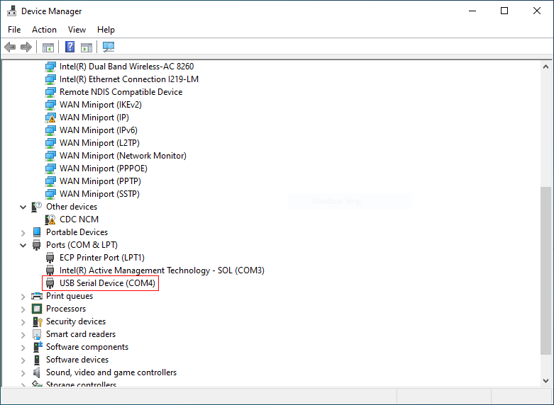
Look under Ports (COM & LPT). My Jetson enumerated as COM4
Open up PuTTy, choose the COM port or the serial device /dev/ttyACM0 for the
Serial line, and put in 115200 as speed.
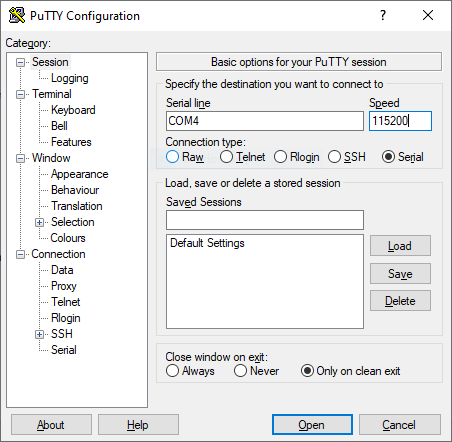
Click “Open”. You should now see the Jetson’s terminal.
Tip
This method can also be helpful if you’ve already configured the
Jetson to connect to a network, but don’t know what the IP address is.
SSH
Note
This only works if you’ve already configured the operating system on the Jetson.
If you’re setting up your Jetson from scratch, you’ll first need to start by
using Monitor/Keyboard or Serial.
In the future, you’ll want to use SSH to login to your Jetson,
as it is far more convenient. SSH is way to login to a Linux system
over a network. However, to do so, you’ll need to know
the IP address of your Jetson. The simplest way to figure this out if
you don’t know is to login via serial, and then run the command
if you’ve connected the Jetson to ethernet or
if you’ve connected the Jetson to WiFi.
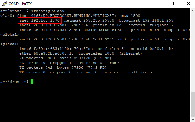
If you have yet to connect your jetson to the WiFi you can follow instructions for
connecting to internet
prior to returning to connect through ssh.
ssh Command
The quickest way to login to yor Jetson over SSH, is to use the builtin ssh command
in Windows. Open up a command prompt or PowerShell, and run
The first time you log in to your Jetson, you’ll be prompted to accept
the host’s key. Enter yes. You’ll thenbe prompted for your password,
and then you’ll be put into a terminal.
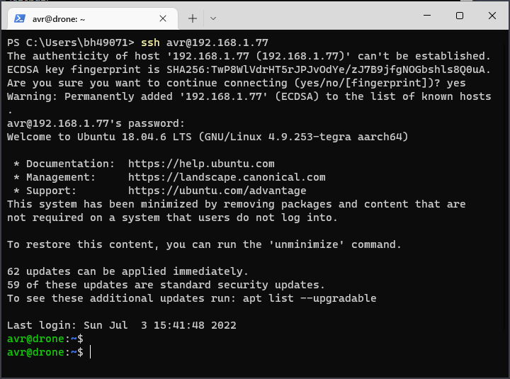
Command line SSH login
PuTTy
If you’re not comfortable with the command line, you can install PuTTy to connect
over SSH. Select the “SSH” button in PuTTy, put in the hostname field <user>@<ip>
and then click the “Open” button.
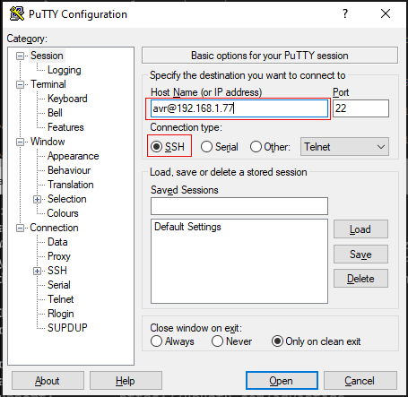
PuTTy SSH Login
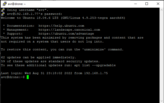
Secondary popup window
You’ll need to accept that you trust a key the first time.
Accept the key
SSH Troubleshooting
Connection closed/reset
If you try to SSH into your Jetson, and you immediately get a connection
timed out error, here’s how to fix it.
First, login to your Jetson via serial. Run the command
and see that you’re getting errors about invalid formats:
Jun 28 18:42:26 drone sshd[8547]: error: key_load_private: invalid format
Jun 28 18:42:26 drone sshd[8547]: error: key_load_public: invalid format
Jun 28 18:42:26 drone sshd[8547]: error: Could not load host key: /etc/ssh/ssh_host_ecdsa_key
Jun 28 18:42:26 drone sshd[8547]: error: key_load_private: invalid format
Jun 28 18:42:26 drone sshd[8547]: error: key_load_public: invalid format
Jun 28 18:42:26 drone sshd[8547]: error: Could not load host key: /etc/ssh/ssh_host_ed25519_key
Jun 28 18:42:26 drone sshd[8547]: fatal: No supported key exchange algorithms [preauth]
If so, run the command
sudo /usr/bin/ssh-keygen -A
to generate a new host key.
Note
You may need to delete or edit your ~/.ssh/known_hosts file after you do this.
Host key verification failed
13.3 - Updating VMC Software
Connecting to Internet
In order to install the AVR software, your Jetson needs to have an internet connection.
The easiest way by far is if you have ethernet available. If so, just plug
an ethernet cable into your Jetson and you should be good to go.
If you don’t have ethernet, you can use a WiFi connection. First, you can list
the available networks with:
Example:

WiFi network list
Hit q to exit the list.
If the Jetson is already connected to a WiFi network, you can disconnect it with:
sudo nmcli device disconnect wlan0
To connect to a WiFi network, run:
# with a password
sudo nmcli device wifi connect <network name> password <password>

# without a password
sudo nmcli device wifi connect <network name>
such as:
sudo nmcli device wifi connect "WI do drones FI" password "Flying_Is_Fun"
If your network name or password has a space or other special characters,
you’ll need to wrap it in quotes as shown above.
Updating
Bell engineers are constantly working on improving the VMC software.
If a new version is ever available, you just need to go into the
directory the repo is cloned to, pull the latest code, and re-run the setup script:
There have been a lot of changes since your Jetson was preloaded with software.
Please ensure that you successfully run git pull in the following steps.
cd ~/AVR-2022/VMC/scripts
git pull
./setup.py
The setup.py script is safe to run at any time,
it won’t mess anything up by running it after everything is already configured.
Troubleshooting
Release is not valid yet
Example output:
Get:1 file:/var/cuda-repo-l4t-10-2-local  InRelease
Ign:1 file:/var/cuda-repo-l4t-10-2-local  InRelease
Get:2 file:/var/visionworks-repo  InRelease
Ign:2 file:/var/visionworks-repo  InRelease
Get:3 file:/var/visionworks-sfm-repo  InRelease
Ign:3 file:/var/visionworks-sfm-repo  InRelease
Get:4 file:/var/visionworks-tracking-repo  InRelease
Ign:4 file:/var/visionworks-tracking-repo  InRelease
Get:5 file:/var/cuda-repo-l4t-10-2-local  Release [564 B]
Get:6 file:/var/visionworks-repo  Release [2,001 B]
Get:7 file:/var/visionworks-sfm-repo  Release [2,005 B]
Get:5 file:/var/cuda-repo-l4t-10-2-local  Release [564 B]
Get:8 file:/var/visionworks-tracking-repo  Release [2,010 B]
Ign:9 https://repo.download.nvidia.com/jetson/common r32.7 InRelease
Get:6 file:/var/visionworks-repo  Release [2,001 B]
Get:7 file:/var/visionworks-sfm-repo  Release [2,005 B]
Get:8 file:/var/visionworks-tracking-repo  Release [2,010 B]
Ign:10 https://repo.download.nvidia.com/jetson/t210 r32.7 InRelease
Err:11 https://repo.download.nvidia.com/jetson/common r32.7 Release
  Certificate verification failed: The certificate is NOT trusted. The certificate chain uses not yet valid certificate.  Could not handshake: Error in the certificate verification. [IP: 23.221.220.78 443]
Err:12 https://repo.download.nvidia.com/jetson/t210 r32.7 Release
  Certificate verification failed: The certificate is NOT trusted. The certificate chain uses not yet valid certificate.  Could not handshake: Error in the certificate verification. [IP: 23.221.220.78 443]
Hit:13 http://ports.ubuntu.com/ubuntu-ports bionic InRelease
Get:15 http://ports.ubuntu.com/ubuntu-ports bionic-updates InRelease [88.7 kB]
Hit:18 http://ports.ubuntu.com/ubuntu-ports bionic-backports InRelease
Hit:19 http://ports.ubuntu.com/ubuntu-ports bionic-security InRelease
Reading package lists... Done
E: The repository 'https://repo.download.nvidia.com/jetson/common r32.7 Release' no longer has a Release file.
N: Updating from such a repository can't be done securely, and is therefore disabled by default.
N: See apt-secure(8) manpage for repository creation and user configuration details.
E: The repository 'https://repo.download.nvidia.com/jetson/t210 r32.7 Release' no longer has a Release file.
N: Updating from such a repository can't be done securely, and is therefore disabled by default.
N: See apt-secure(8) manpage for repository creation and user configuration details.
E: Release file for file:///var/cuda-repo-l4t-10-2-local/Release is not valid yet (invalid for another 2259d 1h 0min 15s). Updates for this repository will not be applied.
E: Release file for file:///var/visionworks-repo/Release is not valid yet (invalid for another 1888d 8h 9min 54s). Updates for this repository will not be applied.
E: Release file for file:///var/visionworks-sfm-repo/Release is not valid yet (invalid for another 1869d 23h 29min 17s). Updates for this repository will not be applied.
E: Release file for file:///var/visionworks-tracking-repo/Release is not valid yet (invalid for another 1869d 23h 30min 39s). Updates for this repository will not be applied.
E: Release file for http://ports.ubuntu.com/ubuntu-ports/dists/bionic/InRelease is not valid yet (invalid for another 1218d 5h 2min 38s). Updates for this repository will not be applied.
E: Release file for http://ports.ubuntu.com/ubuntu-ports/dists/bionic-updates/InRelease is not valid yet (invalid for another 2728d 6h 14min 58s). Updates for this repository will not be applied.
E: Release file for http://ports.ubuntu.com/ubuntu-ports/dists/bionic-backports/InRelease is not valid yet (invalid for another 2728d 5h 42min 43s). Updates for this repository will not be applied.
E: Release file for http://ports.ubuntu.com/ubuntu-ports/dists/bionic-security/InRelease is not valid yet (invalid for another 2728d 5h 39min 48s). Updates for this repository will not be applied.
This usually means your system’s time is not correct. Try running the following
commands to force your system to correct its time.
# After each attempt, run the `date` command to check the time to see if it worked

# Option 1:
sudo hwclock --hctosys

# Option 2:
sudo timedatectl set-ntp off
sudo timedatectl set-ntp on

# Option 3:
sudo service systemd-timesyncd restart

# Option 4:
# This is a final brute-force option that is not recommended.
# Substitute in the date and time you're running the command at
sudo date -s '2022-12-25 12:34:56'
ZED camera not detected
Example output:
WARNING: ZED camera not detected, skipping settings download
Obviously, make sure your ZED Mini camera is plugged in to the Jetson. If not,
plug it in and re-run the setup script.
However, if it is, this sometimes happens because of a finnicky USB detection.
Try running the setup script once or twice more, and unplug the camera and plug
it back in until it picks it up and works.
Connection Issues
Example output:
Get:1 file:/var/cuda-repo-l4t-10-2-local  InRelease
Ign:1 file:/var/cuda-repo-l4t-10-2-local  InRelease
Get:2 file:/var/visionworks-repo  InRelease
Ign:2 file:/var/visionworks-repo  InRelease
Get:3 file:/var/visionworks-sfm-repo  InRelease
Ign:3 file:/var/visionworks-sfm-repo  InRelease
Get:4 file:/var/visionworks-tracking-repo  InRelease
Ign:4 file:/var/visionworks-tracking-repo  InRelease
Get:5 file:/var/cuda-repo-l4t-10-2-local  Release [564 B]
Err:6 http://ports.ubuntu.com/ubuntu-ports bionic InRelease
  Could not connect to ports.ubuntu.com:80 (0.0.0.0). - connect (111: Connection refused)
Err:7 http://ports.ubuntu.com/ubuntu-ports bionic-updates InRelease
  Unable to connect to ports.ubuntu.com:http:
Err:8 http://ports.ubuntu.com/ubuntu-ports bionic-backports InRelease
  Unable to connect to ports.ubuntu.com:http:
Err:9 http://ports.ubuntu.com/ubuntu-ports bionic-security InRelease
  Unable to connect to ports.ubuntu.com:http:
Get:10 file:/var/visionworks-repo  Release [2,001 B]
Get:11 file:/var/visionworks-sfm-repo  Release [2,005 B]
Get:5 file:/var/cuda-repo-l4t-10-2-local  Release [564 B]
Get:12 file:/var/visionworks-tracking-repo  Release [2,010 B]
Get:10 file:/var/visionworks-repo  Release [2,001 B]
Get:11 file:/var/visionworks-sfm-repo  Release [2,005 B]
Get:12 file:/var/visionworks-tracking-repo  Release [2,010 B]
Hit:13 https://repo.download.nvidia.com/jetson/common r32.7 InRelease
Get:14 https://repo.download.nvidia.com/jetson/t210 r32.7 InRelease [2,550 B]
Fetched 2,550 B in 1s (1,843 B/s)
Reading package lists... Done
Building dependency tree
Reading state information... Done
All packages are up to date.
W: Failed to fetch http://ports.ubuntu.com/ubuntu-ports/dists/bionic/InRelease  Could not connect to ports.ubuntu.com:80 (0.0.0.0). - connect (111: Connection refused)
W: Failed to fetch http://ports.ubuntu.com/ubuntu-ports/dists/bionic-updates/InRelease  Unable to connect to ports.ubuntu.com:http:
W: Failed to fetch http://ports.ubuntu.com/ubuntu-ports/dists/bionic-backports/InRelease  Unable to connect to ports.ubuntu.com:http:
W: Failed to fetch http://ports.ubuntu.com/ubuntu-ports/dists/bionic-security/InRelease  Unable to connect to ports.ubuntu.com:http:
W: Some index files failed to download. They have been ignored, or old ones used instead.
If the setup script fails to download something, it likely lost
connection to the internet, or your network is blocking a site it tried
to download content from. Try running the script again.
If that still does not work, look at the VMC software README at
https://github.com/bellflight/AVR-2022/tree/main/VMC/README.md
and the provided list of domain names that the setup script connects to.
Either see if your network administrator can allow these domain names,
or use a personal hotspot or internet connection.
13.4 - Running VMC Software
Networking
Before running the VMC software, we highly recommend that you configure
the Jetson to act as it’s own WiFi network you can connect to. To do this,
login to the Jetson, go into the “VMC” directory,
and run the command ./scripts/wifi.py create:
cd ~/AVR-2022/VMC/
./scripts/wifi.py create
This will walk you through creating a WiFi network that you can connect to.
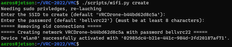
WiFi setup wizard
Tip
You can also use the the disconnect command to disconnect from all WiFi networks
and disable the hotspot, or the connect command to more easily connect to an
existing WiFi network.
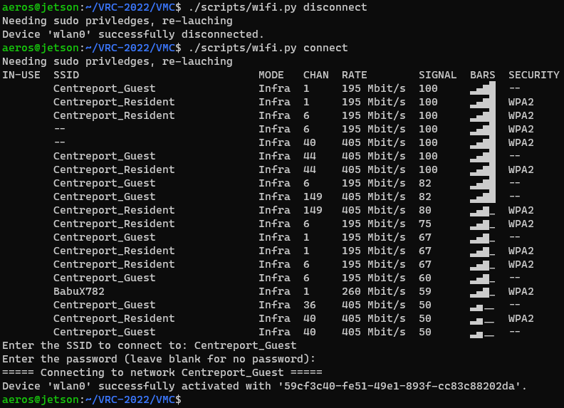
Disconnect/Connect to WiFi networks
After connecting to the WiFi network, your Jetson will always have the IP address
10.42.0.1, which you can use to
connect to via SSH.
Running
After connecting to your Jetson via the hotspot, go into the “VMC” directory,
and run the command ./start.py run:
cd ~/AVR-2022/VMC/
./start.py run
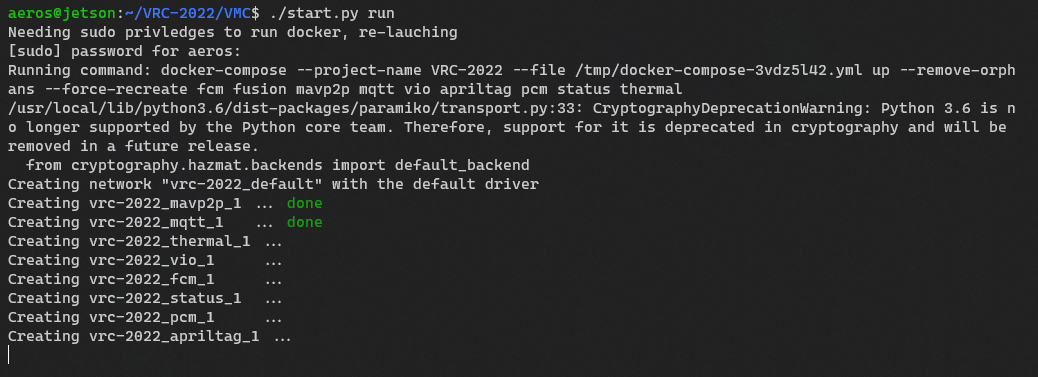
To shutdown the software, press Ctrl+C in the console
window you started the software in. Additionally, run
for good measure.
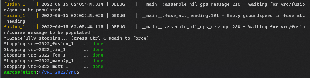
Options
With the basics out of the way, there are some options that can be used
to control which parts of the software are run. By default, a normal set of modules
are run:
./start.py run
# also equivalent to
./start.py run --norm
./start.py run -n
- fcm
- fusion
- mavp2p
- mqtt
- vio
- apriltag
- pcm
- status
- thermal
However, let’s say you have just the bare minimum equipment installed on your drone
(just the ZED Mini camera). You can use the --min option to run only the
following modules which are the bare minimum required for flight:
./start.py run --min
# also equivalent to
./start.py run -m
- fcm
- fusion
- mavp2p
- mqtt
- vio
On the other hand, if you have everything installed, and also
want to run your own code in the sandbox module you can use the --all option:
./start.py run --all
# also equivalent to
./start.py run -a
- fcm
- fusion
- mavp2p
- mqtt
- vio
- apriltag
- pcm
- status
- thermal
- sandbox
Lastly, if you want to run modules not defined in a preset here, you can either
list them all out explicitly, or add the additional modules you want to an exisiting
alias:
# the following are equivalent
./start.py run pcm --min # the --min must come at the end
./start.py run fcm vio mqtt mavp2p fusion pcm
If you ever need help, just add the --help argument to the command:
usage: start.py [-h] [-l] [-m | -n | -a] {run,build,pull,stop} [modules ...]

positional arguments:
  {run,build,pull,stop}
                        Action to perform
  modules               Explicitly list which module(s) to perform the action one

optional arguments:
  -h, --help            show this help message and exit
  -l, --local           Build containers locally rather than using pre-built ones from GitHub
  -m, --min             Perform action on minimal modules (fcm, fusion, mavp2p, mqtt, vio). Adds to any modules explicitly specified.
  -n, --norm            Perform action on normal modules (apriltag, fcm, fusion, mavp2p, mqtt, pcm, status, thermal, vio). Adds to any modules explicitly specified. If nothing else is specified, this
                        is the default.
  -a, --all             Perform action on all modules (apriltag, fcm, fusion, mavp2p, mqtt, pcm, sandbox, status, thermal, vio). Adds to any modules explicitly specified.
Troubleshooting
Sometimes when starting the AVR software, things don’t all start correctly.
Cannot start service pcm
Example output:
Needing sudo privileges to run docker, re-launching
Running command: docker-compose --project-name AVR-2022 --file /tmp/docker-compose-v5eqlg13.yml up --remove-orphans --force-recreate pcm
/usr/local/lib/python3.6/dist-packages/paramiko/transport.py:33: CryptographyDeprecationWarning: Python 3.6 is no longer supported by the Python core team. Therefore, support for it is deprecated in cryptography and will be removed in a future release.
  from cryptography.hazmat.backends import default_backend
Creating network "avr-2022_default" with the default driver
Creating avr-2022_mqtt_1 ... done
Creating avr-2022_pcm_1  ... error

ERROR: for avr-2022_pcm_1  Cannot start service pcm: error gathering device information while adding custom device "/dev/ttyACM0": no such file or directory

ERROR: for pcm  Cannot start service pcm: error gathering device information while adding custom device "/dev/ttyACM0": no such file or directory
ERROR: Encountered errors while bringing up the project.
This error means that the AVR software was unable to connect to the PCC.
If you are not using the PCC, follow the steps above to disable that module.
Otherwise, to test that the PCC is correctly connected to the VMC, run the command:
You’ll get the message ls: cannot access '/dev/ttyACM0': No such file or directory
if the PCC is not connected. If the PCC is connected,
/dev/ttyACM0 will get echoed back.
Try unplugging the PCC and plugging it back into the VMC.
13.5 - Connecting QGC
Once you have the VMC software running on your drone,
you’ll want to connect QGroundControl to it. While not strictly
required for anything, it helps with keeping an eye on the
battery percentage remaining, and ensuring the correct flight mode is selected.
Open QGroundControl, click on the purple “Q” in the top left,
then go to “Application Settings”. Now, go to “Comm Links” and
then click “Add” at the bottom.
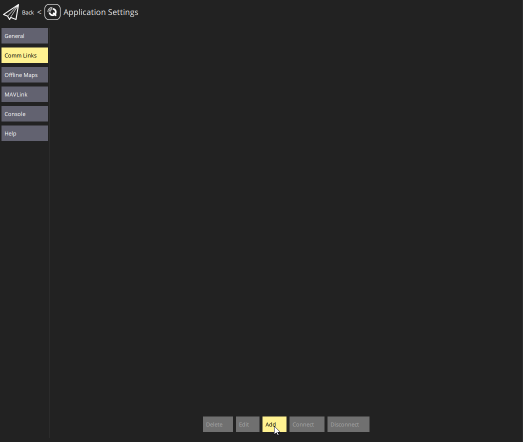
Now, enter a name for this connection, select type of “TCP”, enter the
IP address of your drone, and leave the port number to the default of 5760.
Click “Ok” to add it.
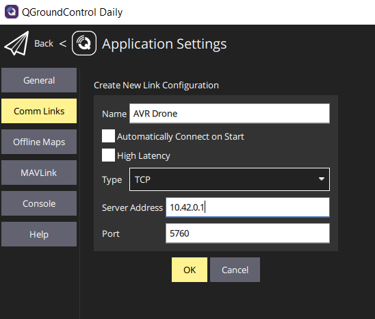
Now whenever you want to connect QGC to your done, go back to
“Application Settings”, “Comm Links”, select your connection,
and click “Connect” at the bottom.
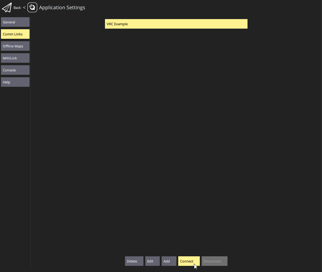
Go back to the main QGC screen and you should see your drone at the Bell headquarters
with 13 satellites visible.
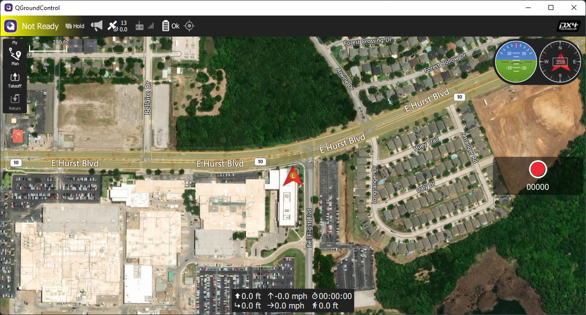
13.6 - Flight Controller Parameters
After configuring the AVR software on your Jetson,
you need to also load custom parameters into your flight controller as well.
These settings configure how the flight controller processes sensor input,
and we need to tell it to unconditionally trust the data the AVR software feeds it.
First, download this parameter file from GitHub:
https://github.com/bellflight/AVR-2022/blob/main/PX4/Params/AVR2022Params.params
The easiest way to download the file is to click the “Raw” button,
then right-click the page, and select “Save page as”.
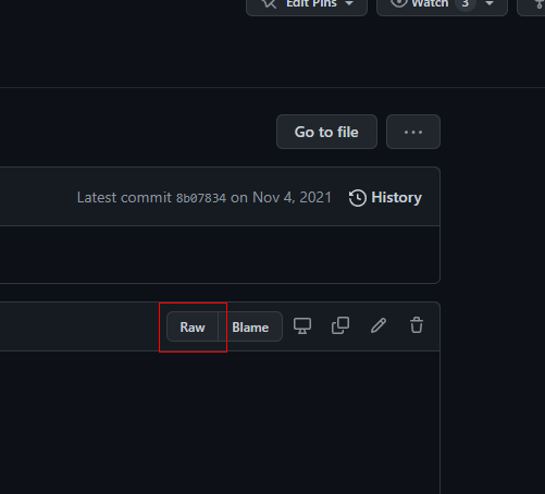
The location of the “Raw” button
Like flashing the flight controller firmware, you’ll need to plug in the FC
to your computer with the MicroUSB cable.
Now, open QGroundControl, click the “Q” in the top left, then
“Vehicle Setup” then “Parameters” at the bottom of the list.
Click on “Tools” in the top right then select “Load from file…”
and select the AVR parameter file you downloaded.
Then click “Ok” to load the parameters.
Then click “Ok” a bunch of times as QGroundControl informs
you that many parameter changes requires a vehicle reboot.

Then go back to “Tools” and select “Reboot Vehicle” at the
bottom of the list to restart the flight controller for the parameters to take effect.
13.7 - GUI
Setup
You should have already setup the AVR GUI when testing your PCC
here.
Usage
Open the application. You’ll be brought to the Connections tab.
After starting the AVR software on your Jetson, put in the Jetson’s
IP address under the “MQTT” section. Leave the port as is.
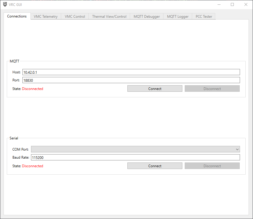
Connections tab
Click “Connect”, and make sure the application properly connects.

Connection state
If the application is unable to connect to your drone, the state will show as
“Failure”. Make sure the software is running, and you got the IP address correct.
After the application connects, all the VMC-related tabs will become enabled.
Tabs
The functionality of the application is broken up into multiple tabs. These
tabs are automatically enabled/disabled based on the connectivity currently
available. These tabs can be re-ordered as desired. Additionally,
the tabs can be popped out into separate windows to create a multi-pane
view, either by double clicking the tab, or right-clicking and selecting “Pop out”.
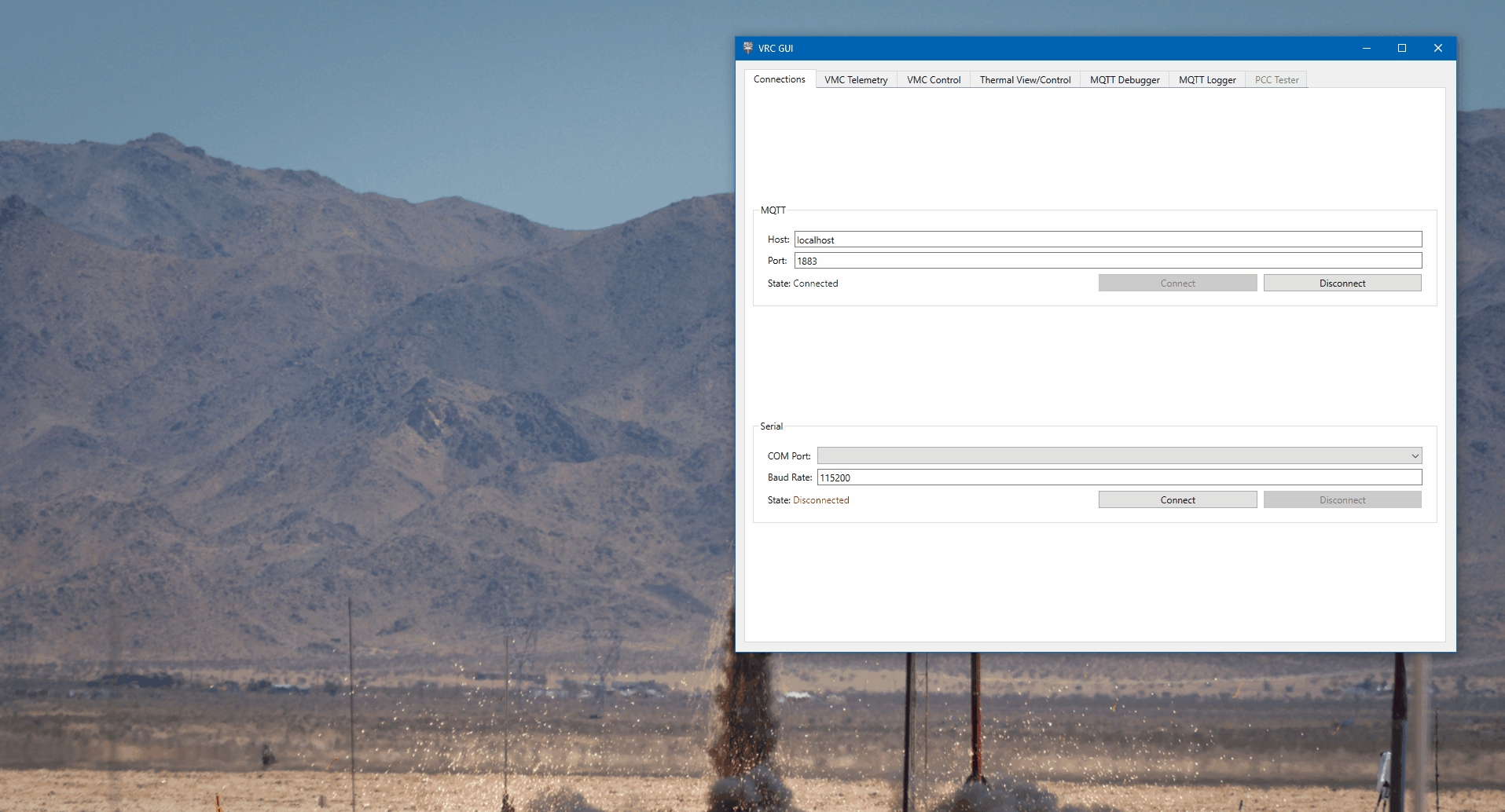
You can also double-click to pop out a tab
To reattach a tab, just close the window.
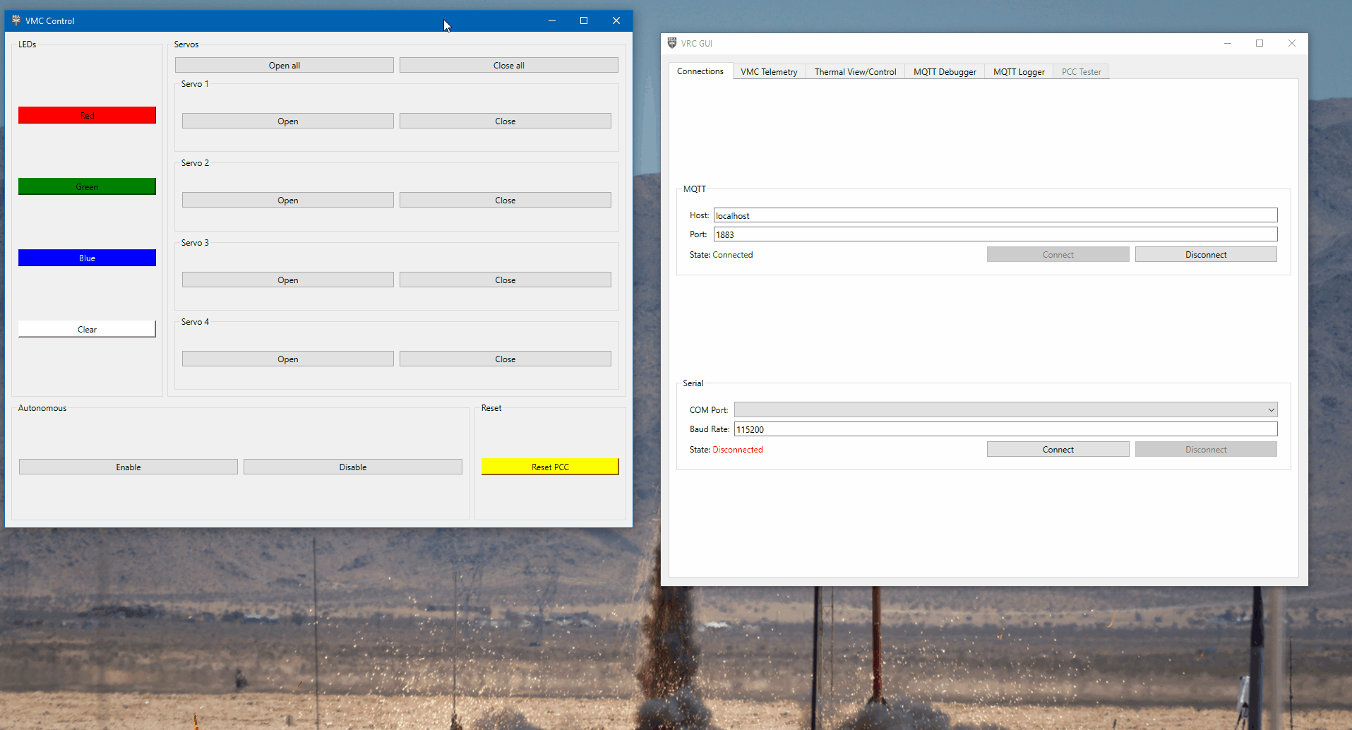
Re-attaching a tab
VMC Telemetry
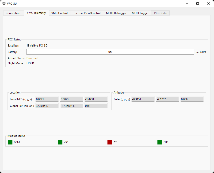
VMC Telemetry Tab
This tab is a sort of QGroundControl “Lite” that shows the most important
telemetry information from the drone. This is NOT a full replacement for
QGroundControl, but quick view of important information while your drone is flying.
At the top is the status of the flight controller, with information about
the current GPS fix, battery level and voltage, armed status, and selected
flight mode.
In the middle is the current location of the drone in local and global coordinates,
along with the current attitude of the drone in roll, pitch, yaw.
Finally, at the bottom is a display of the status of the software modules
required for stabilized flight and April Tag detection. These indicators will
turn green once MQTT messages are received from a module, and will
turn red if more than a second has elapsed since the last received message.

Module status indicators
If all 4 indicators are green, you are good to fly!
VMC Control
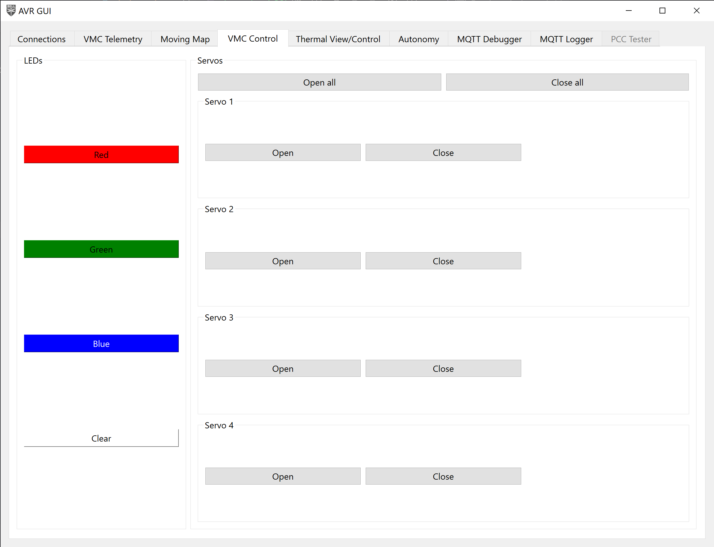
VMC Control Tab
This tab allows you to control various aspects of the drone, including the
LEDs, and servos connected to the PCC.
Click the individual open/close buttons to open/close individual servos, or click
the open/close all buttons at the top of open/close all of the servos at once.
Click the color buttons to change the color of the LEDs
to one of the presets (red, green, blue). The “clear” button at the bottom
turns off the LEDs.
Autonomy Control
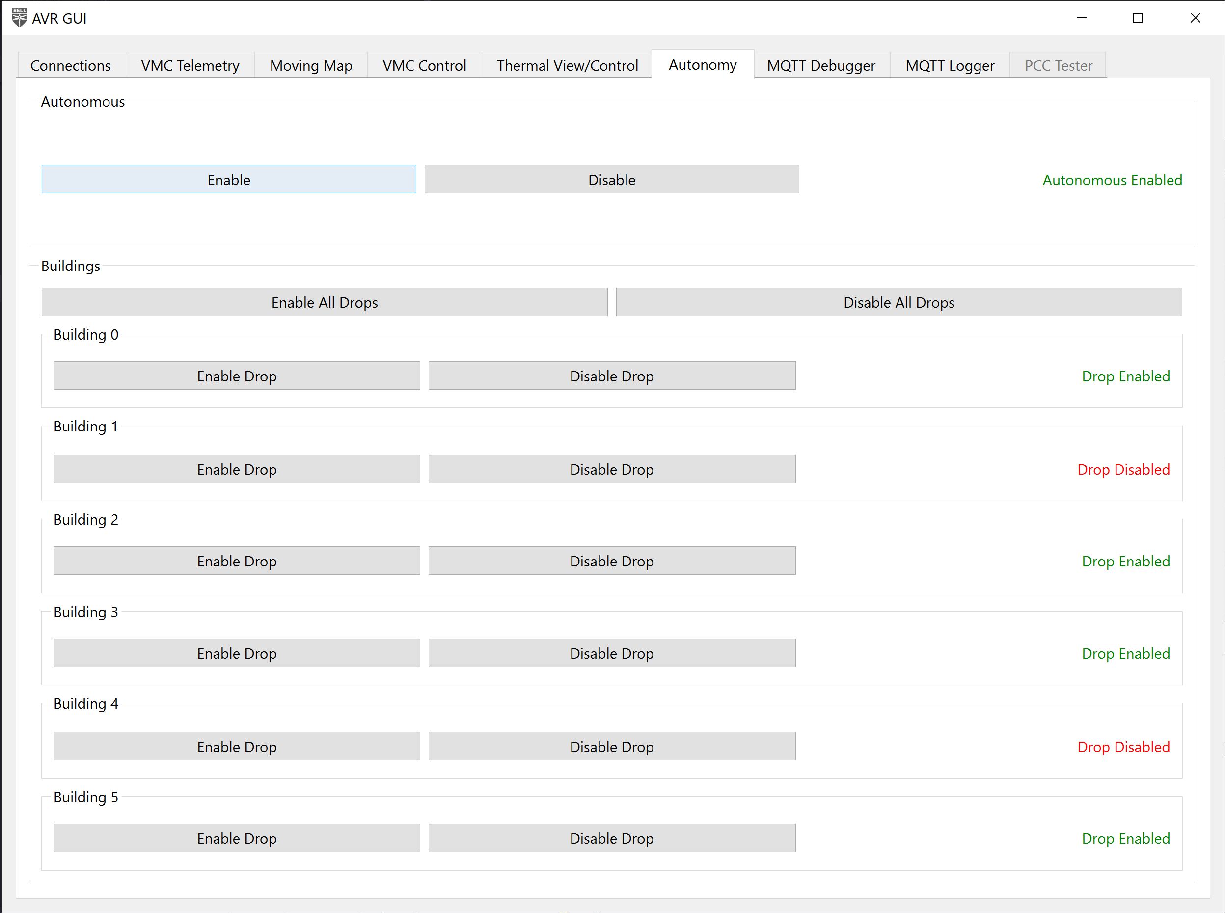
Autonomy Control Tab
Autonomous Enable
The “Autonomous” buttons in the tab,
this is purely optional for the teams that have chosen to write autonomous code.
These buttons send a message to the MQTT topic avr/autonomous with a payload of:
// enable button
{
    "enable": true,
}

// disable button
{
    "enable": false,
}
For any teams writing their own autonomous code,
they can write a listener for this topic to enable/disable their
autonomous code at certain points, rather than have it run continuously
the entire time.
Example implementation:
from bell.avr.mqtt.client import MQTTModule
from bell.avr.mqtt.payloads import AvrAutonomousPayload

class Sandbox(MQTTModule):
    def __init__(self) -> None:
        self.enabled = False
        self.topic_map = {"avr/autonomous": self.on_autonomous_message}

    ...

    def on_autonomous_message(self, payload: AvrAutonomousPayload) -> None:
        self.enabled = payload["enable"]

    def autonomous_code(self) -> None:
        while self.enabled:
            do_stuff()
Building Autonomous Enable Drop
Additionally, buttons for enabling/disabling autonomous water drops are provided on this
page.
These buttons send a message to the MQTT topic avr/autonomous/building/drop with
a payload of:
{
  "id": 0,
  "enabled": true
}
This message can be used to tell you drone what buildings are on fire and if you want to
drop water on it or not. For a full list of which buildings have water drops please
refer to the game manual. The activity of using the avr/autonomous/building/drop
will be implemented by the students in the sadbox module.
[Hint: the above example can also be used in this scenario]
Thermal View/Control
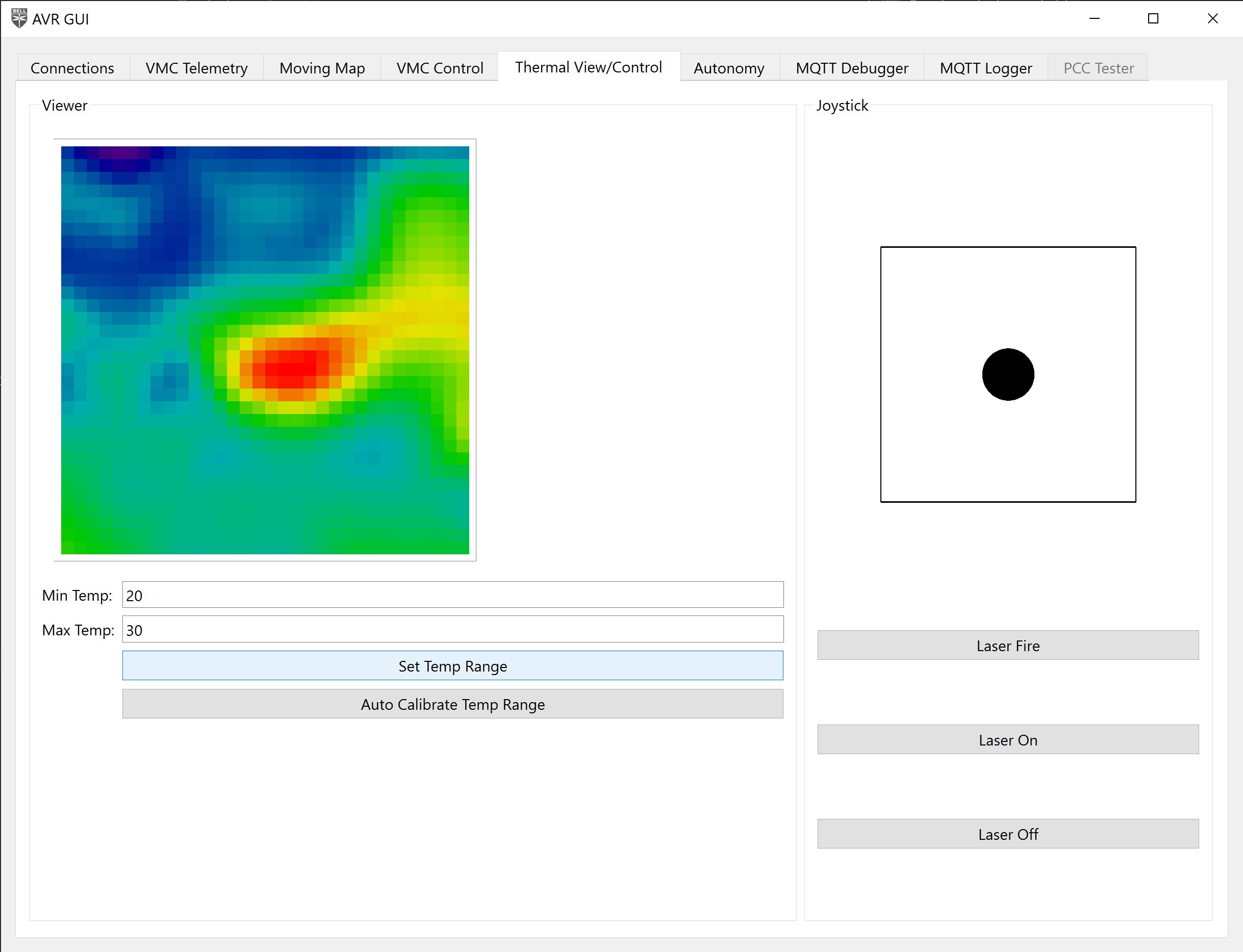
Thermal view and control tab
This tab shows a view of the thermal camera, and provides a means of
controlling the gimbal and turning the associated laser on and off.
You can either calibrate your thermal cameras range manual by typing in a min and max
value, or you can use the auto calibrate feature to get a dynamic range.
To use the gimbal, click and drag the black dot and move it around within the box.
The bounds of the box are the gimbal’s limit.
Moving Map
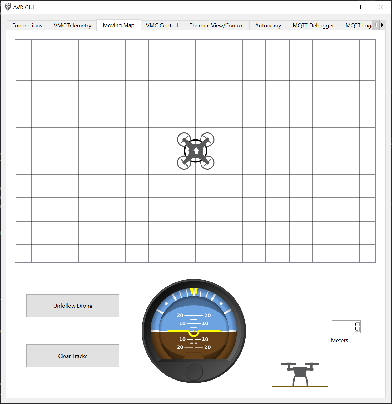
Moving Map Tag
A map of your drones movements has been included for reference while flying.
You can use this to reference your location, roll, pitch, yaw, or altitude.
MQTT Debugger
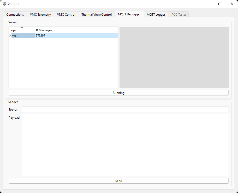
MQTT Debugger Tab
This tab is a debugging tool that shows all MQTT messages
that are passing through the AVR software, along with giving
you the ability to manually send messages.
In the top half of the tab is the message viewer. On the left side
is a tree view of all the topics with the levels deonting “/“s in the topic name.
When you click on a topic, on the right side will show the last payload recieved
on that topic, and will update live.
Viewing live data from a topic
To show or hide topics, click the arrow on the left of the trip item to expand or hide
the next level, or right-click the topic and select
“Expand Children” or “Collapse Children”. To expand or collapse everything, select
“Expand All” or “Collapse All”.
Expanding or collapsing child topics
At the bottom of the viewer is a “Running”/“Paused” button that will cause the
viewer to update live, or freeze the current view. This is not associated with the
MQTT connection in the Connections tabs. This only stops the viewer from updating
when trying to look at data.

Running/paused button
In the bottom half of the tab is the message sender. You can put in the topic
you want to send a message to and the payload of the message. Click the “Send”
button at the bottom to send the message, and you will see it show up above
in the message viewer.
Message sender
Danger
Send MQTT messages at your own risk! This is a debugging tool,
and incorrectly formatted messages, or messages with bogus data
may cause the flight software to crash, digitially and/or physically.
If you want to copy an existing message, right-click on an item in the message
viewer and select “Preload data”. This will prefill the topic and payload
of the message into the message sender.
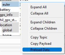
Preload data option
Alternatively, you can select “Copy Topic” or “Copy Payload” to copy the topic
or payload to your clipboard.
MQTT Logger
MQTT Logger tab
This tab is another debugging tool, that can be used to create
a log of MQTT data that can be analyzed at a later time.
Clicking the “Record” button at the bottom
will create a folder called “logs” next to the .exe and create a new
log file with the starting timestamp in the name. The log file is just a .csv file
with 3 columns:
- Timestamp that the message was sent
- Topic of the message
- Payload of the message (JSON data as a string)
Short example:
Timestamp,Topic,Payload
2022-05-15T16:05:21.861220,avr/fcm/location/local,"{""dX"": -2.5455074310302734, ""dY"": -1.5015729665756226, ""dZ"": 2.0492169857025146, ""timestamp"": ""2022-05-15T18:43:51.529153""}"
2022-05-15T16:05:21.865960,avr/fcm/attitude/euler,"{""roll"": 0.3597148656845093, ""pitch"": -1.1968730688095093, ""yaw"": -115.29061126708984, ""timestamp"": ""2022-05-15T18:43:51.533150""}"
2022-05-15T16:05:21.867091,avr/fcm/location/global,"{""lat"": 32.8085261, ""lon"": -97.1563602, ""alt"": -0.1720000058412552, ""hdg"": -6245.665443087664, ""timestamp"": ""2022-05-15T18:43:51.534187""}"
2022-05-15T16:05:21.867533,avr/fcm/velocity,"{""vX"": 0.009999999776482582, ""vY"": 0.0, ""vZ"": -0.009999999776482582, ""timestamp"": ""2022-05-15T18:43:51.535720""}"
2022-05-15T16:05:21.886569,avr/fusion/hil_gps,"{""time_usec"": 1652640231557357, ""fix_type"": 3, ""lat"": 328085260, ""lon"": -971563603, ""alt"": 165206, ""eph"": 20, ""epv"": 5, ""vel"": 0, ""vn"": 0, ""ve"": 0, ""vd"": 0, ""cog"": 24600, ""satellites_visible"": 13, ""heading"": 24638}"
2022-05-15T16:05:21.890844,avr/fcm/location/global,"{""lat"": 32.8085261, ""lon"": -97.1563602, ""alt"": -0.1720000058412552, ""hdg"": -6245.528183606103, ""timestamp"": ""2022-05-15T18:43:51.557302""}"
2022-05-15T16:05:21.891264,avr/fcm/velocity,"{""vX"": 0.009999999776482582, ""vY"": 0.0, ""vZ"": -0.009999999776482582, ""timestamp"": ""2022-05-15T18:43:51.560023""}"
2022-05-15T16:05:21.901353,avr/fcm/location/local,"{""dX"": -2.5456197261810303, ""dY"": -1.5016621351242065, ""dZ"": 2.049142837524414, ""timestamp"": ""2022-05-15T18:43:51.571278""}"
2022-05-15T16:05:21.909915,avr/vio/position/ned,"{""n"": -254.60606976676002, ""e"": -143.7991712686676, ""d"": -370.6543833582757}"
2022-05-15T16:05:21.913765,avr/vio/orientation/eul,"{""psi"": -2.870100228693062, ""theta"": 0.7509557925331154, ""phi"": -1.982899257543946}"
2022-05-15T16:05:21.914391,avr/fusion/position/ned,"{""n"": -254.60606976676002, ""e"": -143.7991712686676, ""d"": -370.6543833582757}"
2022-05-15T16:05:21.914799,avr/vio/heading,"{""degrees"": 246.38824134310744}"
2022-05-15T16:05:21.915277,avr/vio/velocity/ned,"{""n"": 0.006583199572207324, ""e"": -0.020817144593196127, ""d"": 0.02579902535054221}"
2022-05-15T16:05:21.915846,avr/vio/confidence,"{""tracker"": 41}"
To stop recording, click the “Stop recording” button. This will stop writing to the
log file.
You can do a lot of things with this data. For example,
you can plot how your drone flew through 3D space using
matplotlib and pandas:
import json

import matplotlib.pyplot as plt
import pandas as pd

# load in the CSV file
df = pd.read_csv("MQTTLog_2022-05-10_17-08-27.csv")
# parse the JSON data into the Pandas dataframe
df = df.join(df["Payload"].apply(json.loads).apply(pd.Series))
# filter to only data from the avr/fcm/location/global topic
px4_data = df[df["Topic"] == "avr/fcm/location/global"]

fig = plt.figure()
ax = plt.axes(projection='3d')

ax.plot3D(px4_data["lat"], px4_data["lon"], px4_data["alt"], label="PX4")

ax.set_xlabel("Latitude")
ax.set_xlabel("Longitude")
ax.set_zlabel("Altitude")

plt.legend()
plt.show()
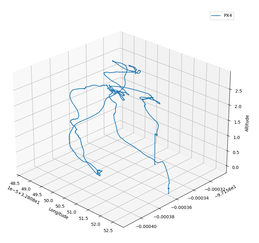
Using matplotlib to plot a drone’s flight
Another example is plotting the drone’s battery remaining over time:
import csv
import datetime
import json

import matplotlib.pyplot as plt

filename = "MQTTLog_2022-05-15_16-05-21.csv"

x = []
y = []

with open(filename, "r") as fp:
    # create a DictReader to read the CSV file
    reader = csv.DictReader(fp)
    for row in reader:
        # only get data from the avr/fcm/battery topic
        if row["Topic"] == "avr/fcm/battery":
            # parse the JSON data
            payload = json.loads(row["Message"])

            # convert the timestamp to a Python datetime object
            x.append(datetime.datetime.fromisoformat(row["Timestamp"]))
            y.append(payload["soc"])

fig = plt.figure()

plt.plot(x, y)

plt.xlabel("Time")
plt.ylabel("Battery %")

plt.ylim(0, 105)
plt.grid(True)

plt.show()
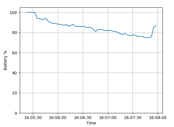
Using matplotlib to plot battery percentage
PCC Tester

PCC Tester tab
This is covered when
testing the PCC
14 - Checkpoint 3: Position Flight Test
15 - Peripheral Drone Assembly
15.1 - Gimbal Assembly
Overview
This section details how to assemble your gimbal.
The gimbal allows the ground station operator to aim the FPV camera, thermal camera, and
laser pointer at targets on the field independently of the drones position/orientation.
The gimbal assembly will be used to detect hot spots on the field, put out fires using
your water cannon, and perform reconnaissance with your FPV camera .
The gimbal uses 2 servos (very similar to servos used in previous years)
to control the pan and tilt of the drone.
Pan is the rotation about the z-axis meaning this controls the left or right camera angle.
Pan gets its name because it keeps an object in the picture or secures a panoramic effect.
Tilt is the rotation abut the y-axis meaning it controls the up and down camera angle.
Obtain the
gimbal parts
from the 3D printing section, 2 servos and associated hardware, a mosfet,
the thermal camera, laser module, FPV camera, and long F-F dupont jumper wires.
Note
Be sure you have the latest 3D printed parts as there have been changes to the pan part
to accommodate your specific servo horn.
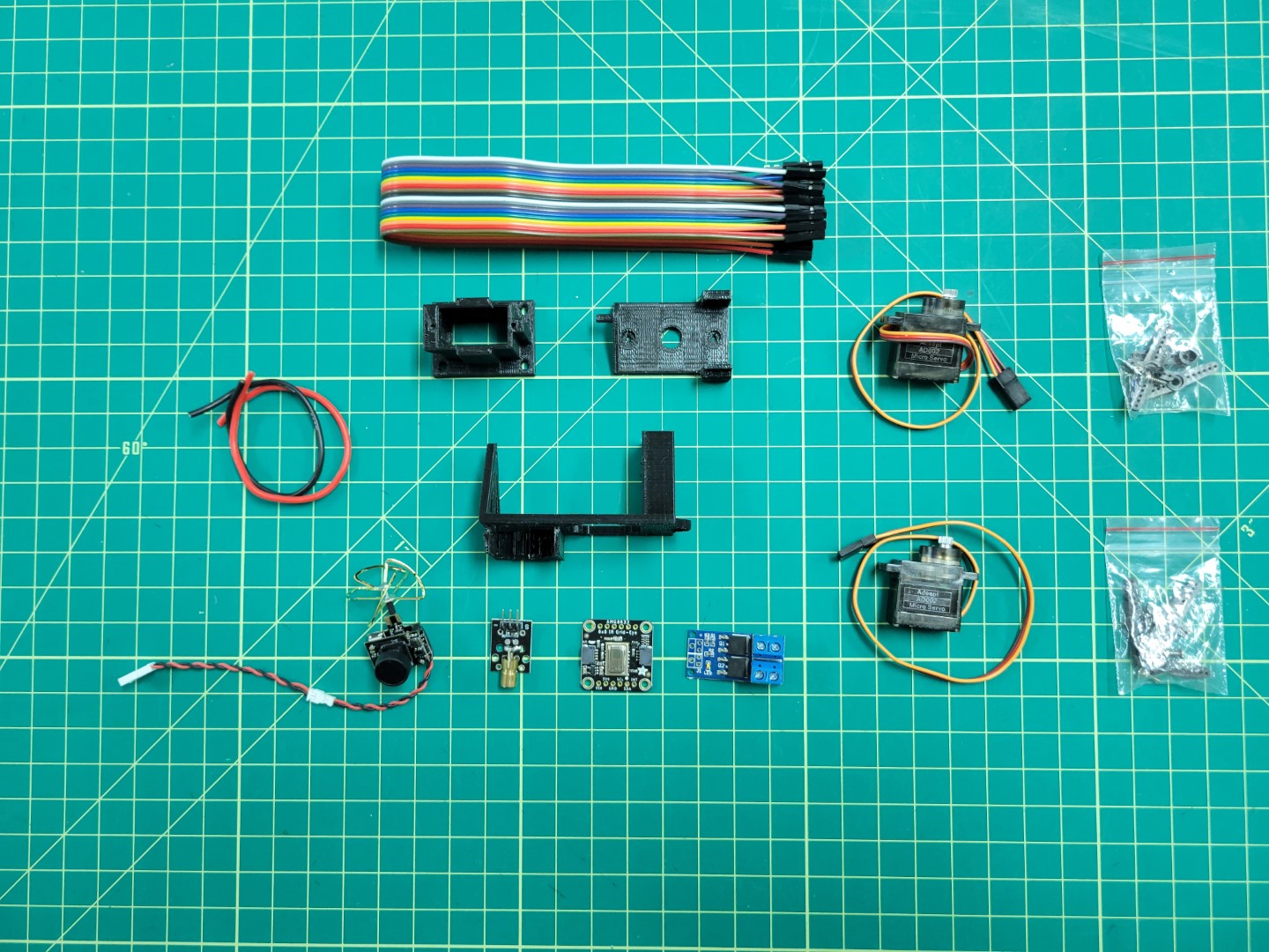
Gimbal Parts Overview
Gimbal Base
Start with the gimbal base.
Pass your servo wire through the slot on the slide and slide servo into place.
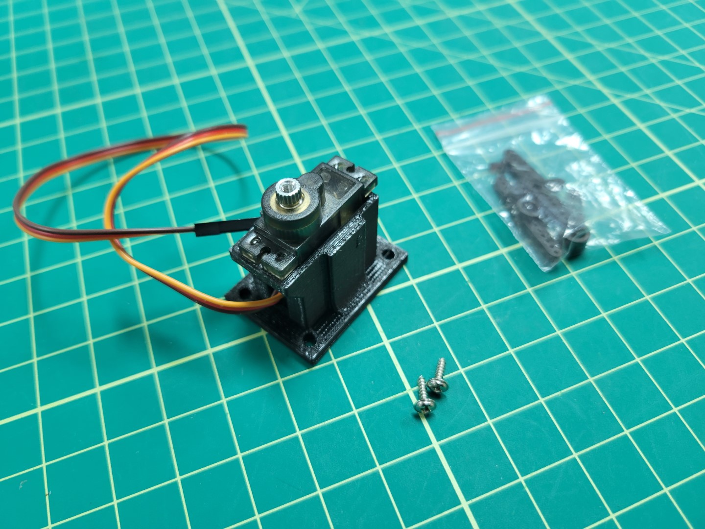
Gimbal Base Servo Placement
Secure the servo into the gimbal base using the servo hardware screws as shown below.
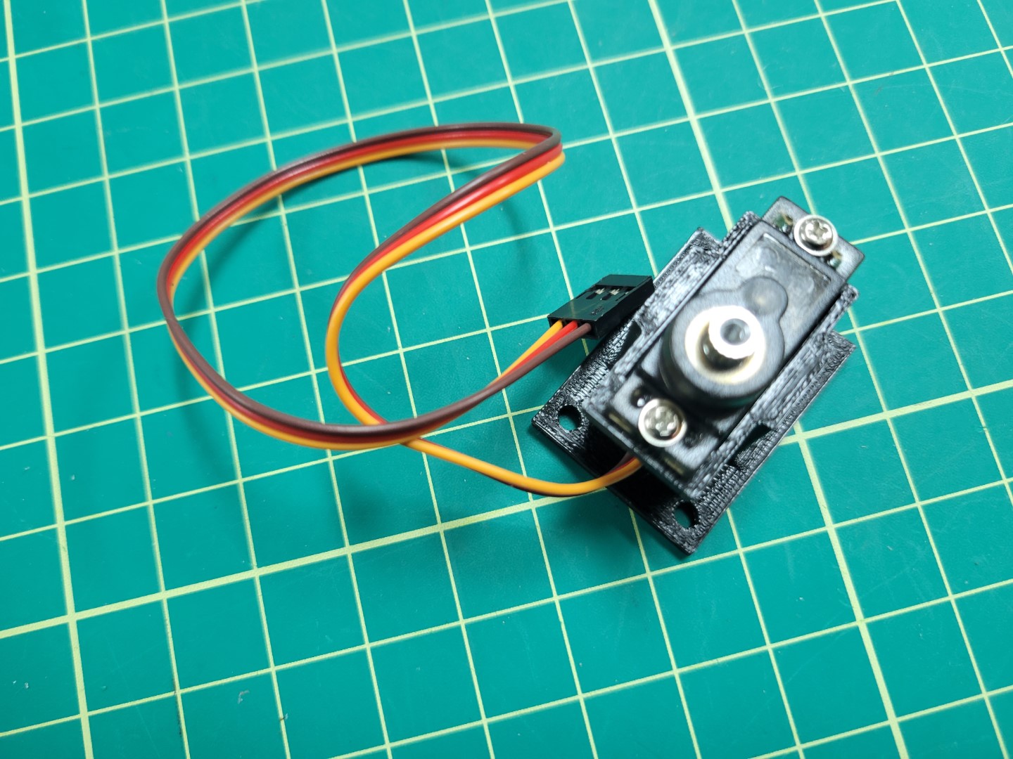
Gimbal Base Servo Mounting
Gimbal Pan
Next you will attach the servo horn with 2 arms to the
bottom of the gimbal pan part using the servo hardware.
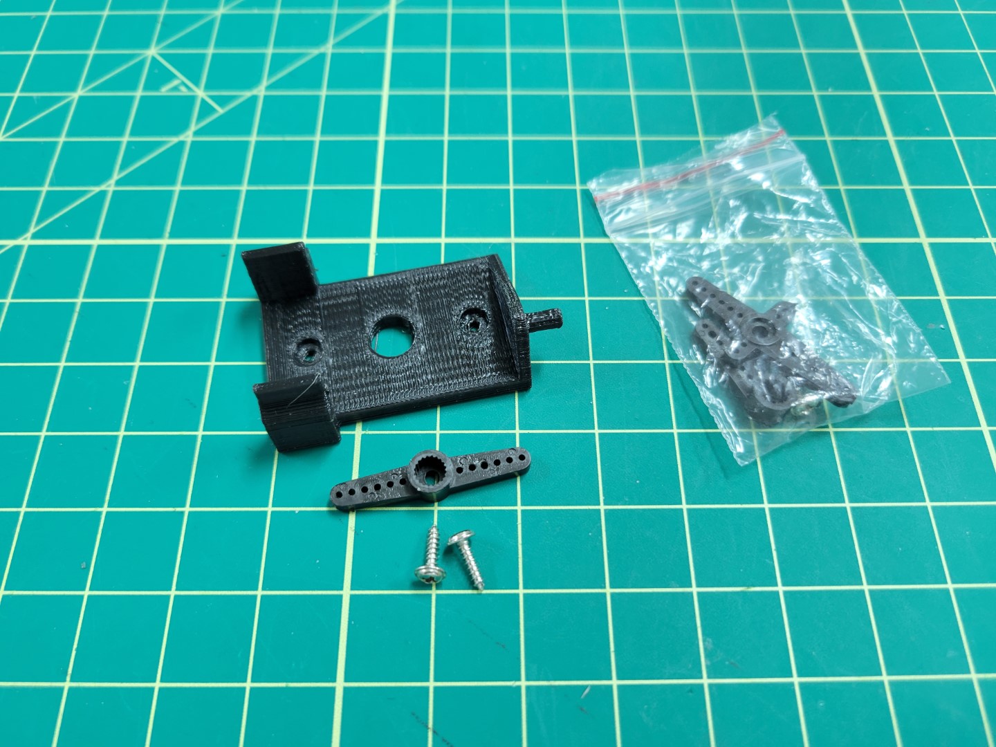
Gimbal Pan Servo Hardware
Be sure the geared part of the servo horn is facing away from the connecting face.
Align the center hole and the 2 holes (one hole away from the end of the servo arm) with
the holes on the pan part. Screw through the part to attach your servo horn to the pan part.
If done successfully your screws heads should sit flush with the bottom of the gimbal pan.
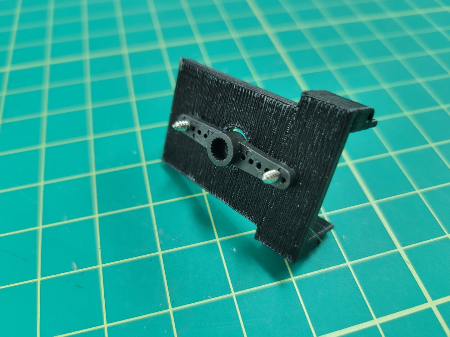
Gimbal Pan Servo Horn Attachment
Place a second servo in the gimbal pan part, this servo will be used to control the tilt of the gimbal. The gimbal gear and the tilt attachment arm should be on the same axis. Align the servo gear with the tilt attachment arm of the opposite side of the 3D printed part. Screw the tilt servo into the two holes on the side pan assembly; the final product of which should look like the following photo.
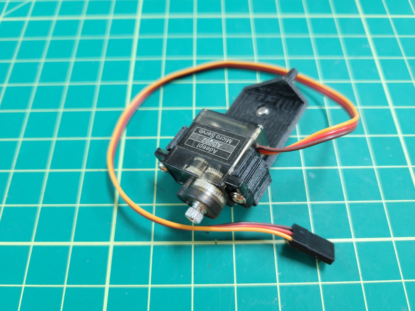
Tilt servo attached to gimbal pan part
Gimbal Tilt
Next we will be assembling the tilt mechanism.
This is where all of our sensors will be mounted.
Thermal Camera Mounting
The thermal camera will be mounted in the center of our gimbal tilt part.
Use 4 screws from the peripheral bag to attach the thermal camera to the drone.
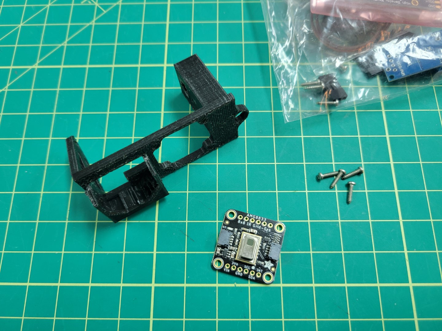
Thermal Camera Mounting Overview
After screwing in, it should look like the photo below.
Note
Make note of the thermal camera’s orientation. This will be important for properly viewing the thermal image in the AVR GUI.
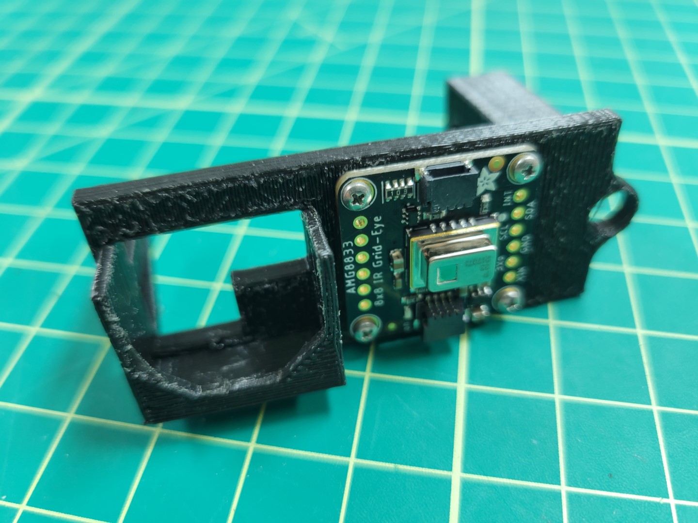
Mounted Thermal Camera
We will wire and test this in following sections.
FPV mounting
The FPV camera is mounted on the left side of the part (as shown in the picture).
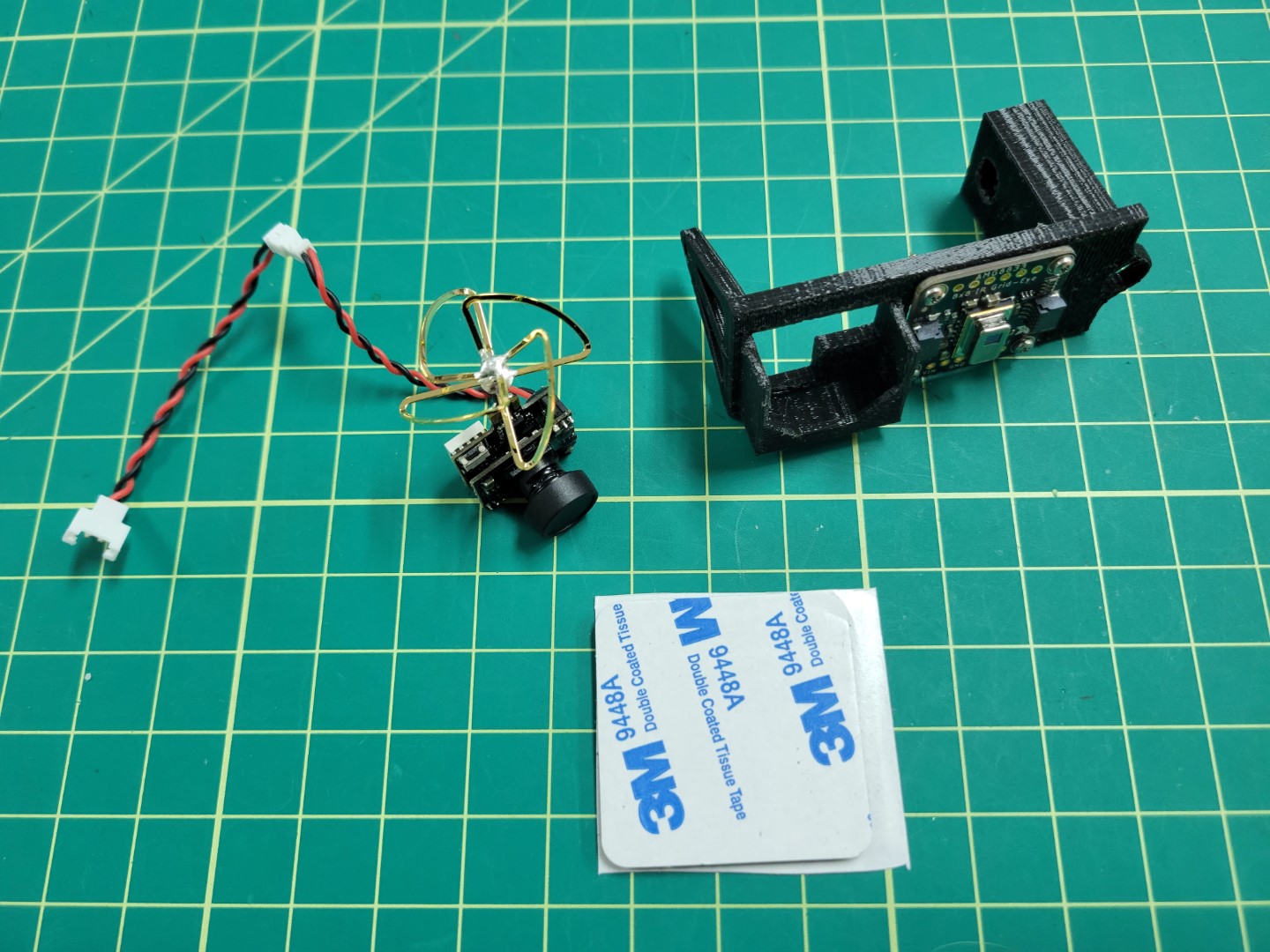
FPV Mounting Overview
Cut a 3M double sided tape to the size of the base of the protruding area of the tilt part and place.
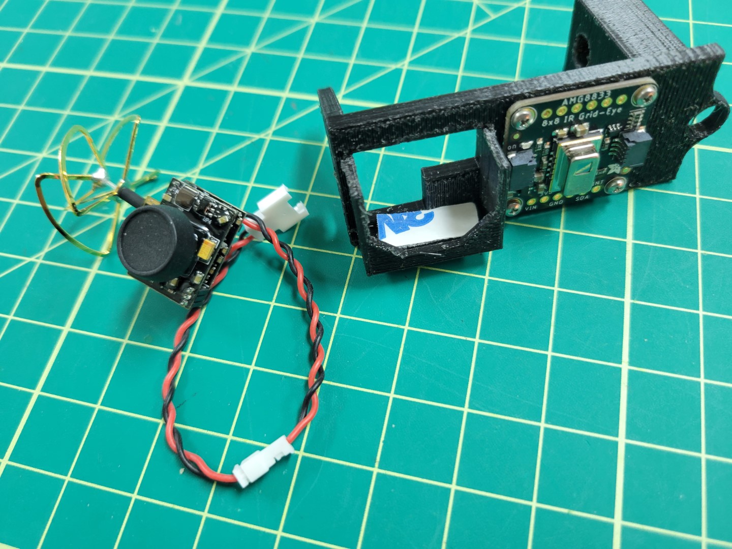
FPV Double Sided Tape Placement
Slide the camera into the slot and ensure that the camera is secured.
You should be able turn the part upside down without the camera falling out.
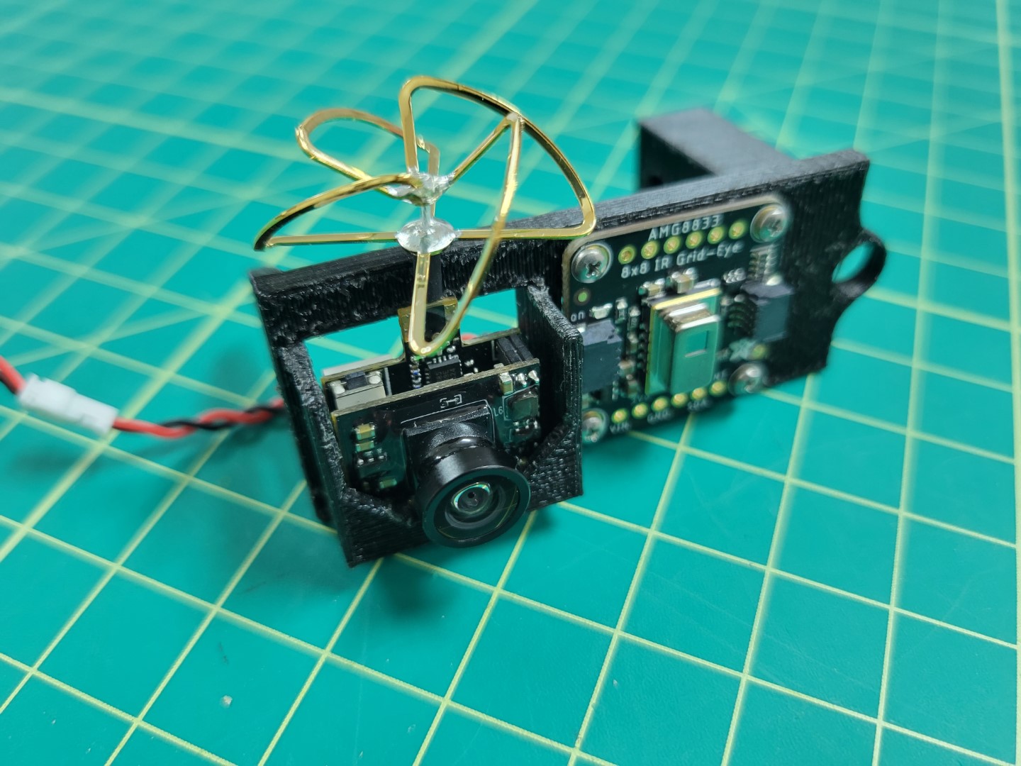
FPV Mounted in Tilt Assembly
We will wire and test this in following sections.
Mount Servo Horn
Next place your servo horn into the the recess on the tilt part.
We find that using a small amount of super glue is helpful in holding the servo in place before we attach it.
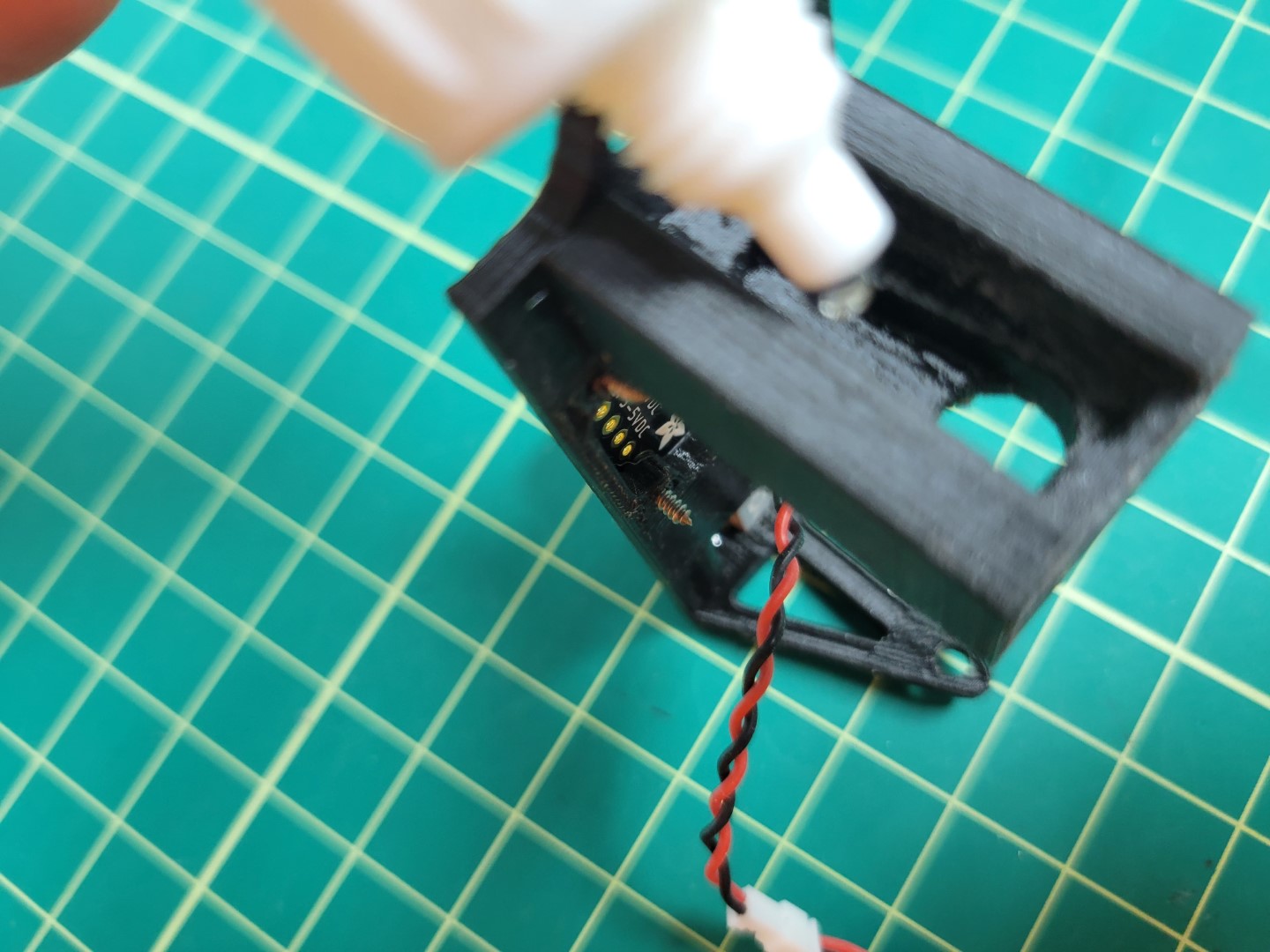
Tilt Servo Horn Mounting
The only remaining part of the gimbal assembly components is the laser,
but we will come back to that after fully assembling the gimbal on the drone.
Gimbal Assembly
Now that all of the assembly 3D parts have been assembled we can start mounting the gimbal to the drone.
Note
Before performing this section, ensure you have connected to your drone with
the GUI
as we will need to use it in order to calibrate the Gimbal.
First, mount the Gimbal base to the drone using 10mm 3M screws included in your kit.
Use the 1st and 3rd slotted holes from the front of the drone to mount the gimbal base.
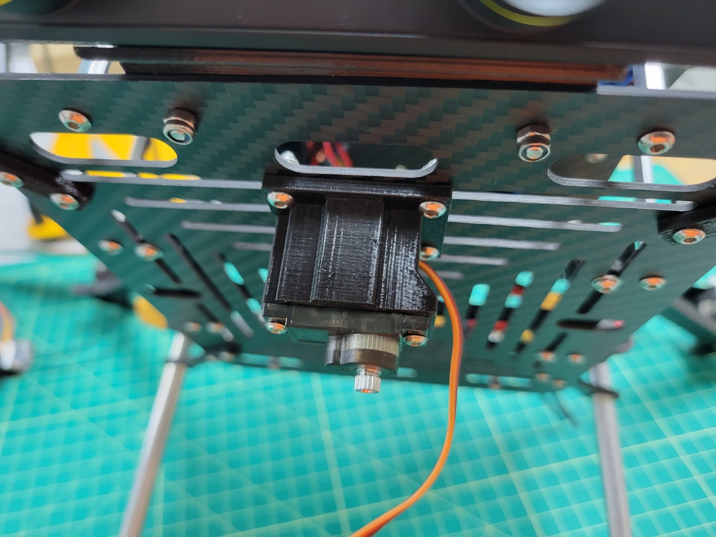
Gimbal Base Mounted
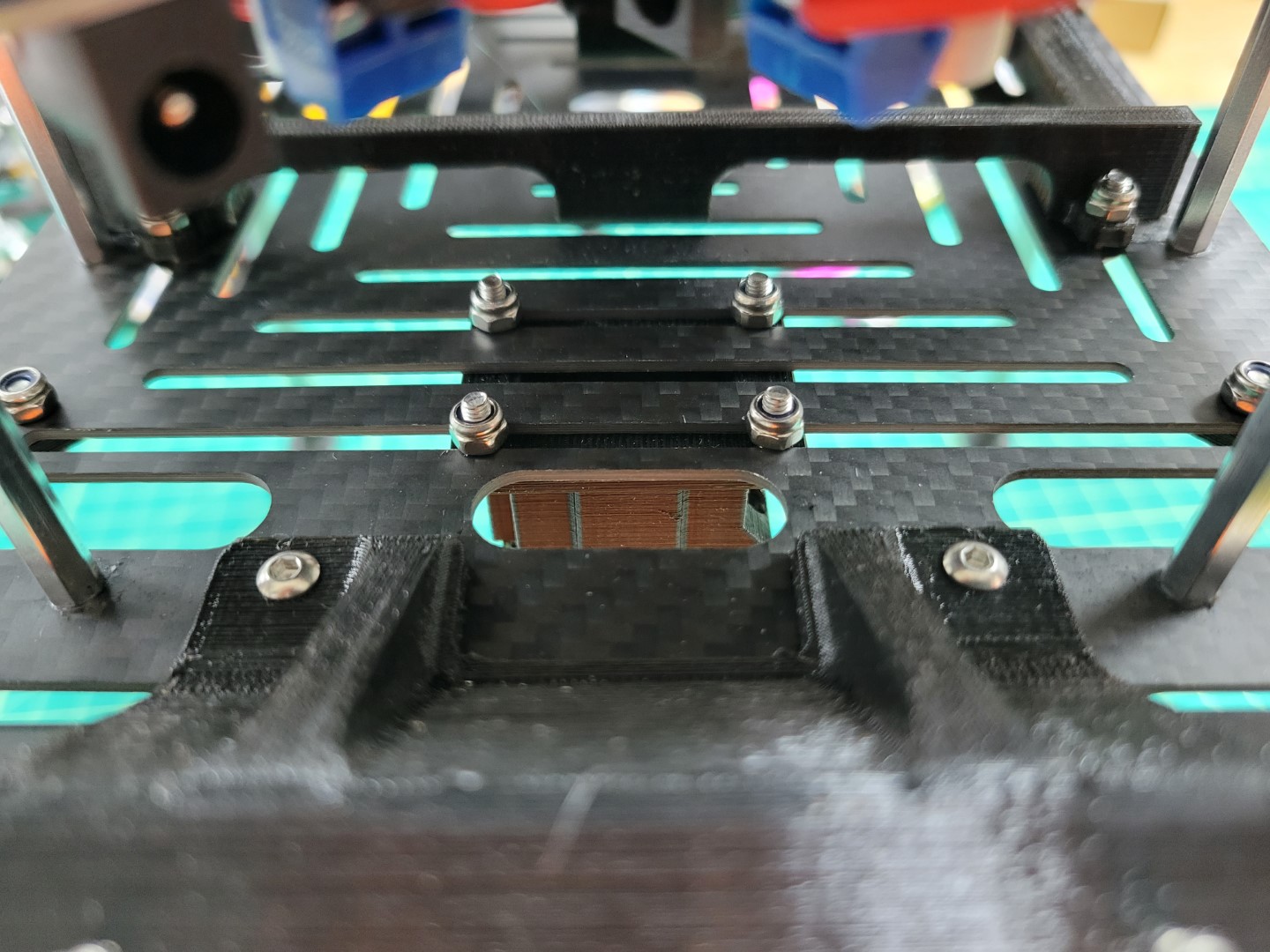
Lock Screws
Pan and Tilt Calibration
Please watch the video below to understand calibrating your gimbal’s pan and tilt range of motion.
Note
If you do not have the “invert joystick” option in your GUI be sure you have the
latest stable release
of the GUI.
Command used in video for starting the services
cd AVR-2022/VMC
./start.py run mqtt pcm
Pan and Tilt Servo Wiring
You can clean up your servo wiring by using 12" servo extenders. You will run them up through the bottom, mid, and top plates and finally connect them to your PCC as shown in the photo below.
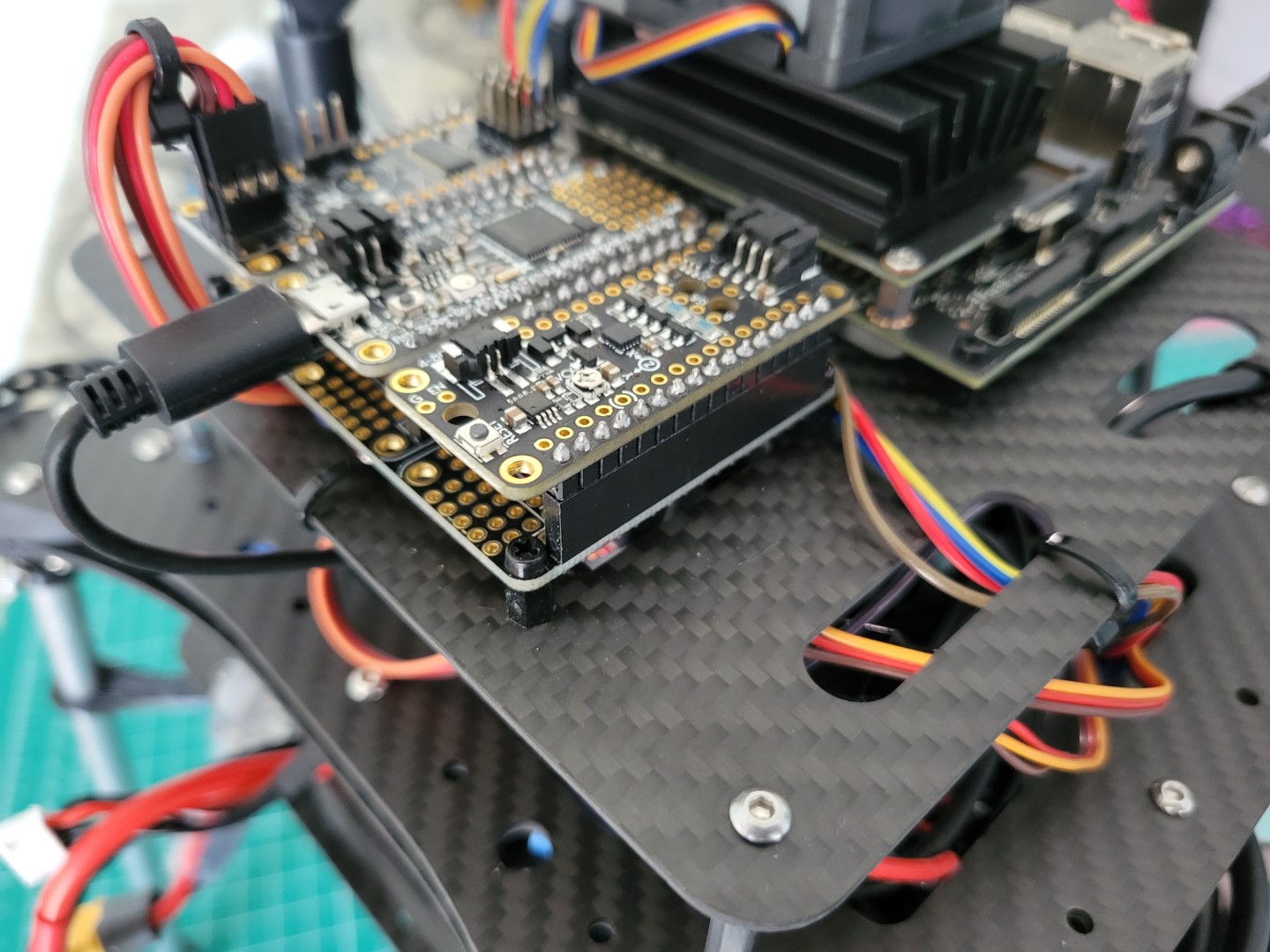
12" servo extenders routed up to PCC
There is no right or wrong way to manage your servo wiring. The only important thing is that you have your pan and tilt servos plugged into the correct ports as covered in the calibration video.
Laser Pointer Mounting
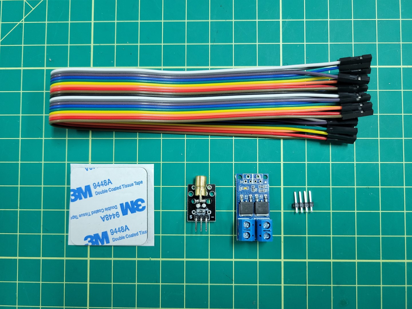
Components for laser mounting and wiring
Cut a small piece of your 3M double sided tape and place it on the end of your laser pointer being sure not to obstruct the view of the laser barrel.
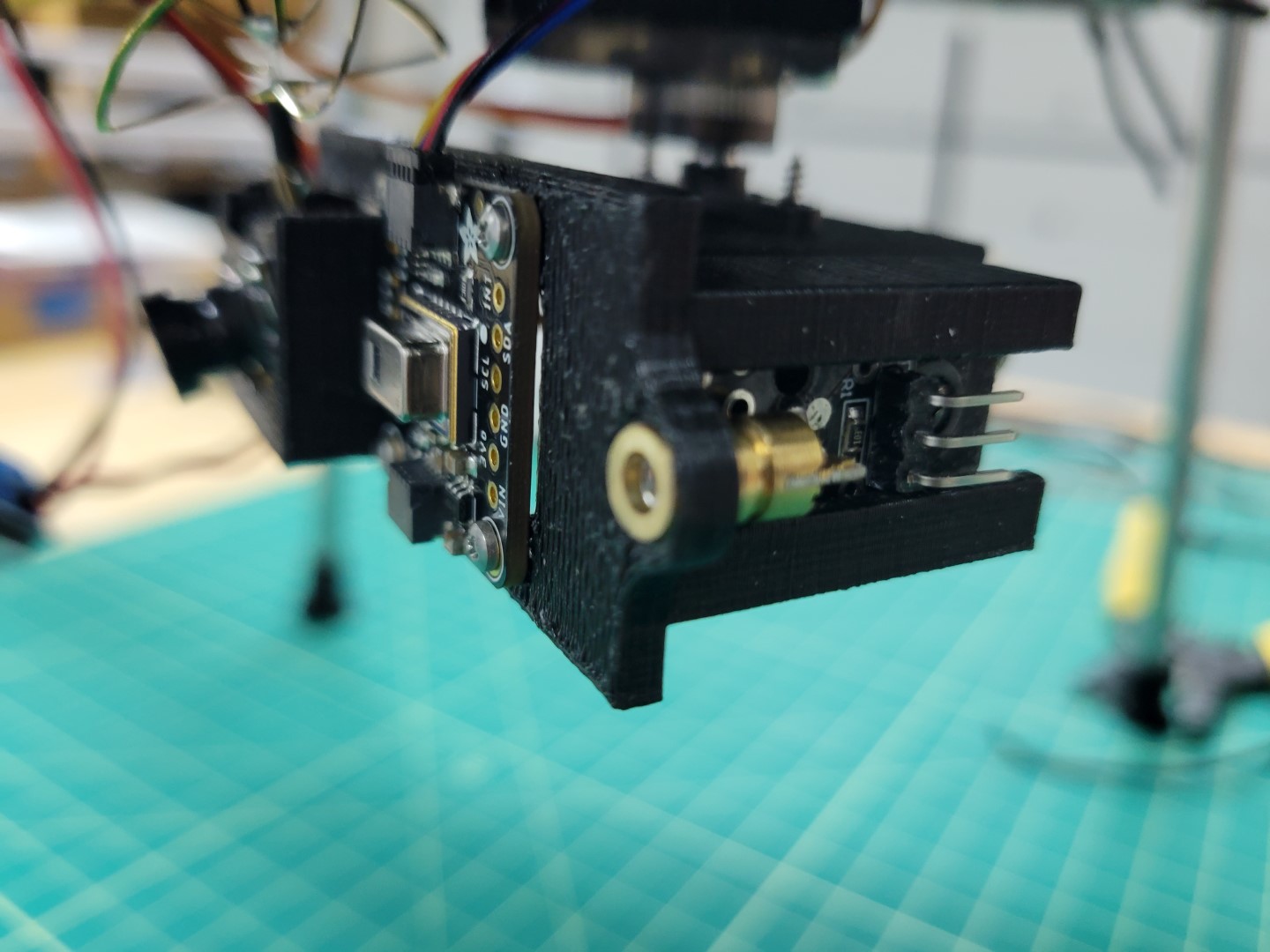
Laser mounted in gimbal
Powering Laser and the FPV
Next we will be focusing on the FPV and the Laser wiring as shown in the following wiring diagram.
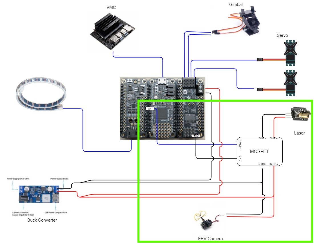
PCC Wiring
Solder extra header pins from the PCC section onto mosfet pins J1.
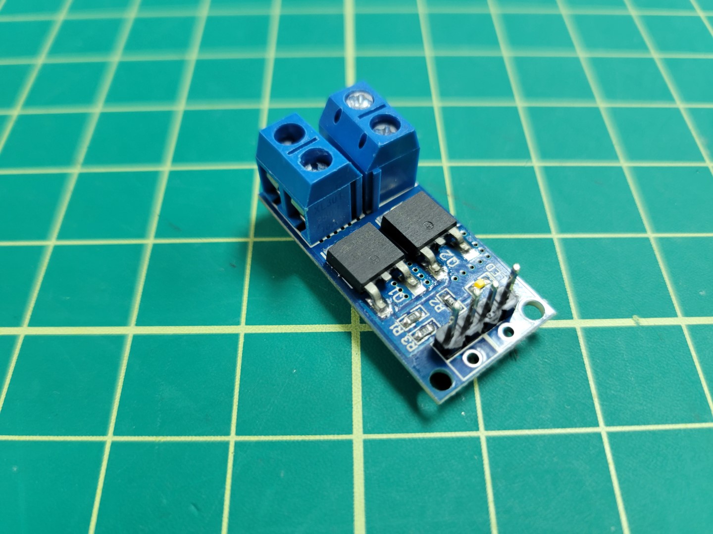
Mosfet with header pins soldered
Cut wires (black and red) approximately 6" in length.
Screw wires into the PCC Buck converter output terminal. There will be two wires coming out of the positive and negative terminals as shown in the photo below.
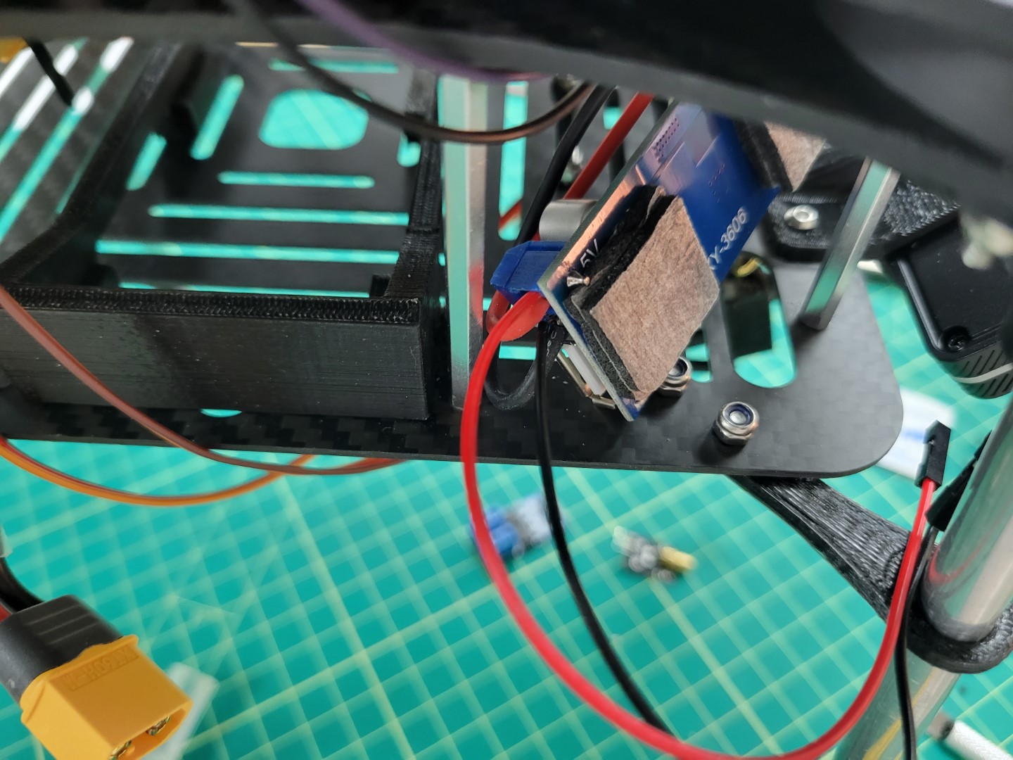
Leads that will power mosfet
Cut the extender provided with the FPV camera at the connector as shown in the following photo.
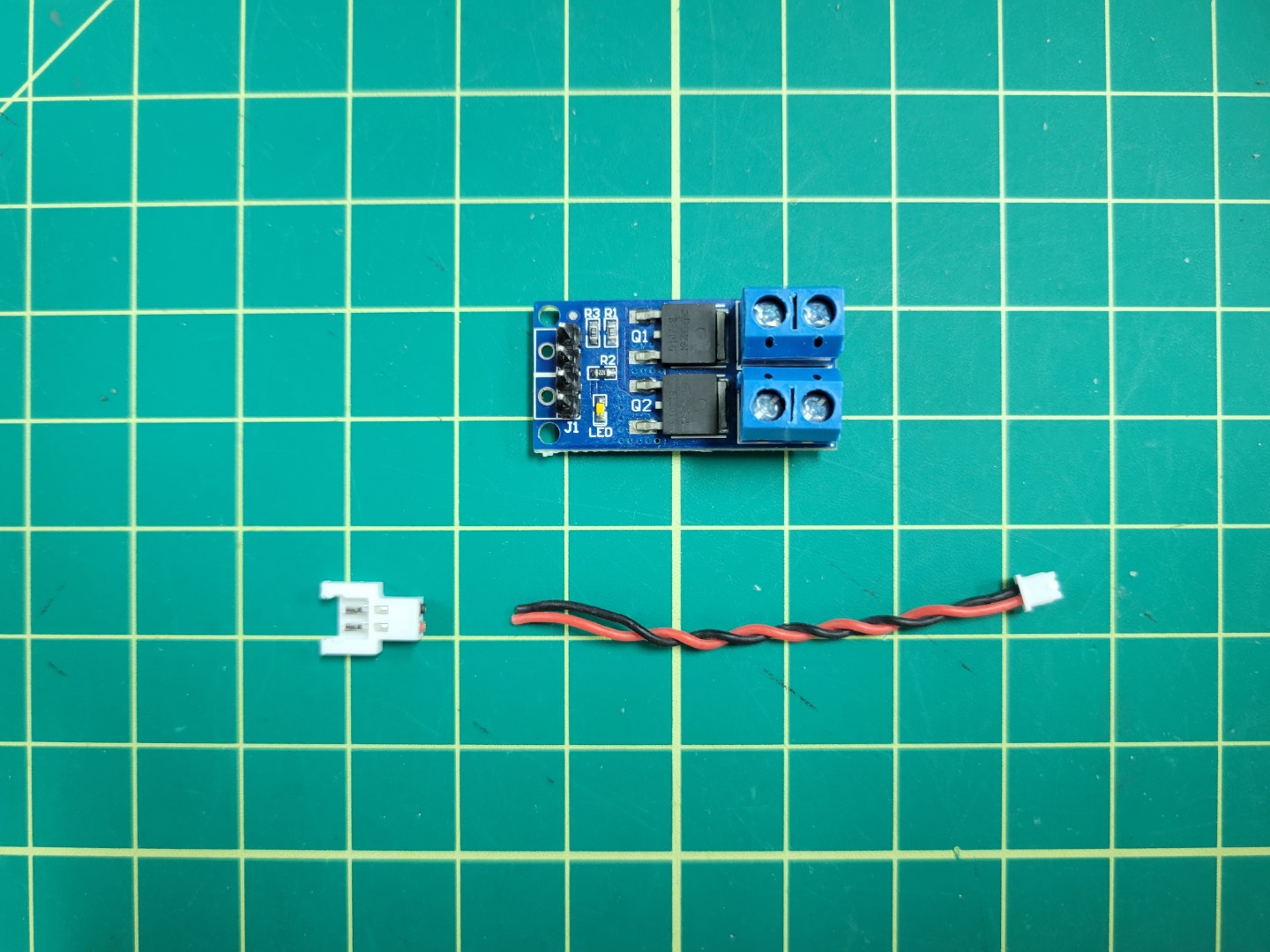
FPV camera cable ready to connect to mosfet
Place both the power and FPV wire ends into the mosfet input terminals and screw down to terminal to secure.
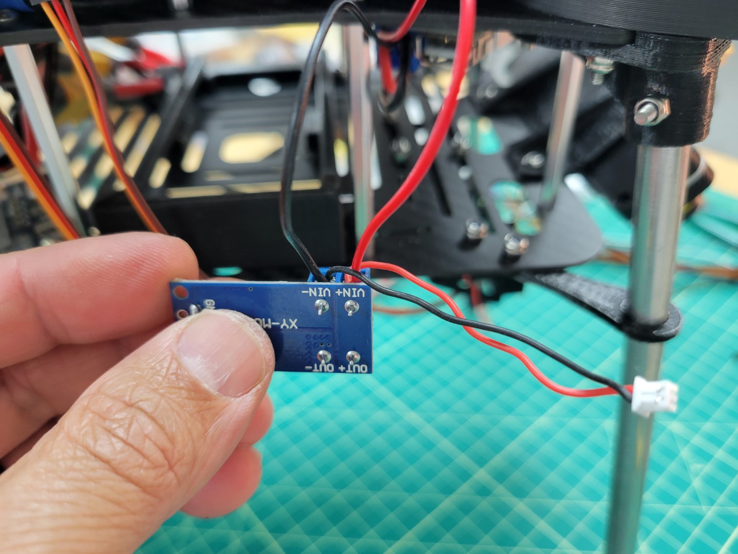
Mosfet Power Supply
Stack 2 layers of 3M double sided tape on the mosfet as shown in the following photo.
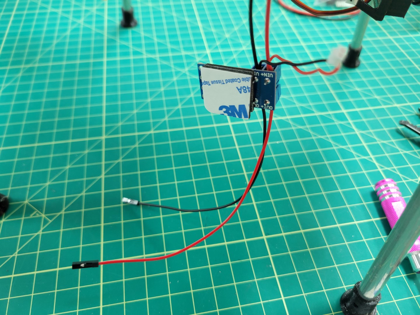
Mosfet Mounting
Next mount your mosfet and plug in your FPV camera.
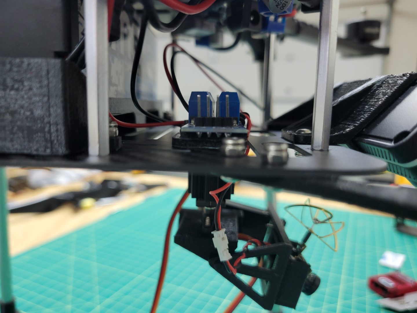
Mosfet Mounting Location
Wire mosfet from the PCC. Wire A4 will run to the PWM. The Ground pin will run to GND.
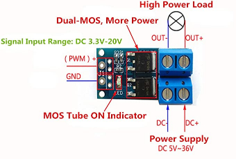
Mosfet Diagram
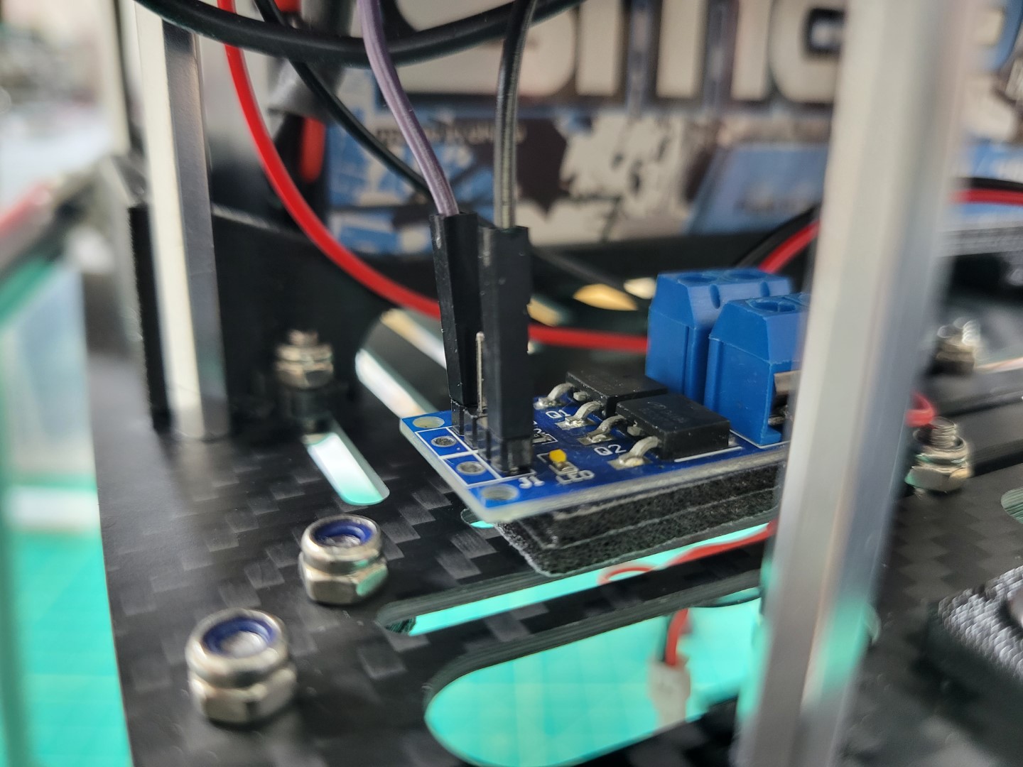
Mosfet Wiring
Cut and strip one side of a black and red Female-Female dupont jumper wire to approximately 8" in length.
Screw wires in to their respective terminal blocks.
Place the black and red wire on the ground and signal pins of the laser pointer respectively as shown in the following photo.
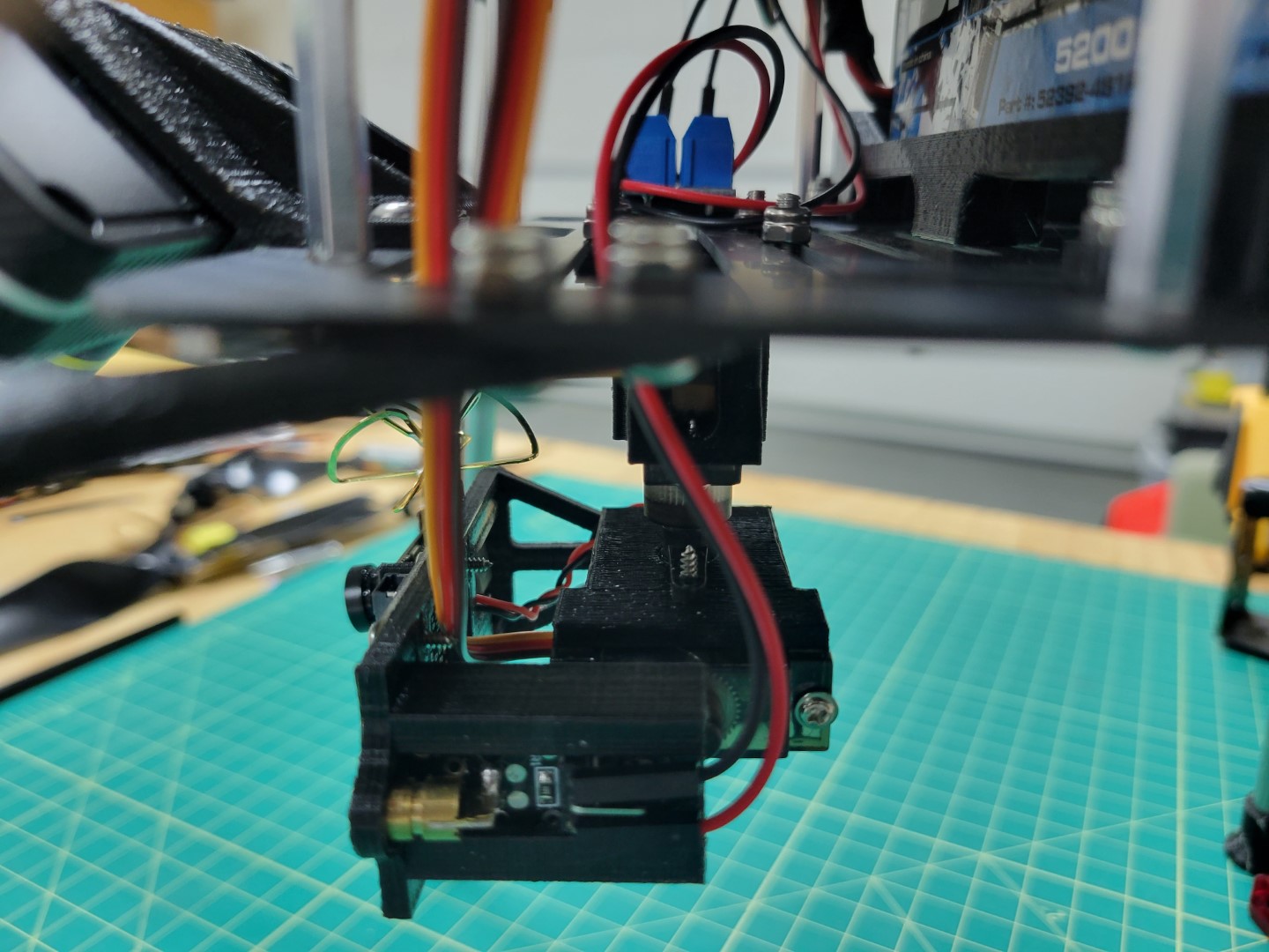
Laser Wiring
Thermal Camera
Locate the thermal camera JST SH 4-pin connecting cable and four 12" jumper wires with corresponding colors from your kit.
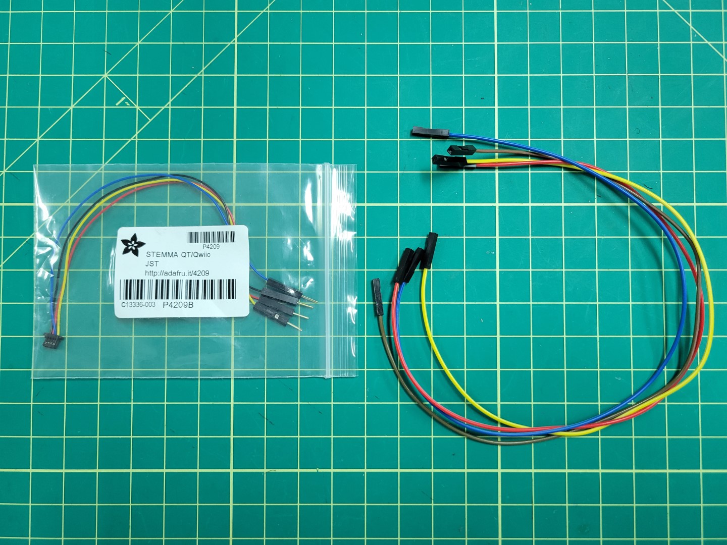
Thermal Camera Wires
Connect long female-female jumper wires of corresponding colors.
It may be beneficial to add a little bit of electrical tape to ensure they do not come undone.
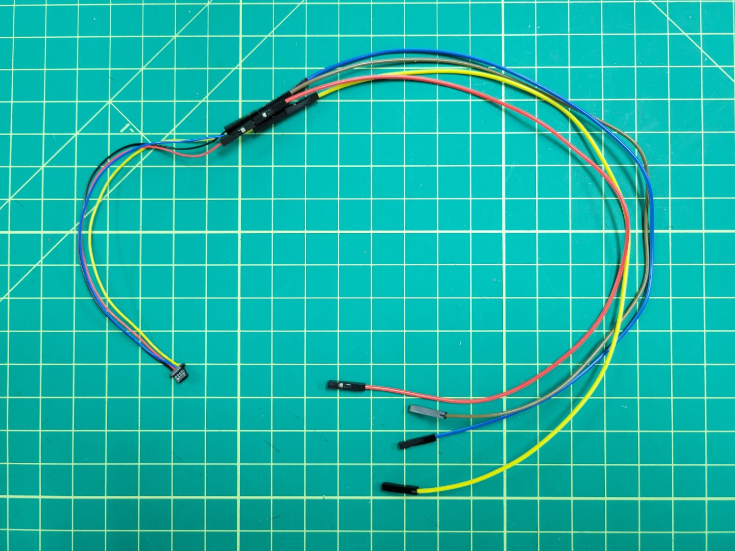
Thermal Camera Wiring
Remove your plastic end pieces.
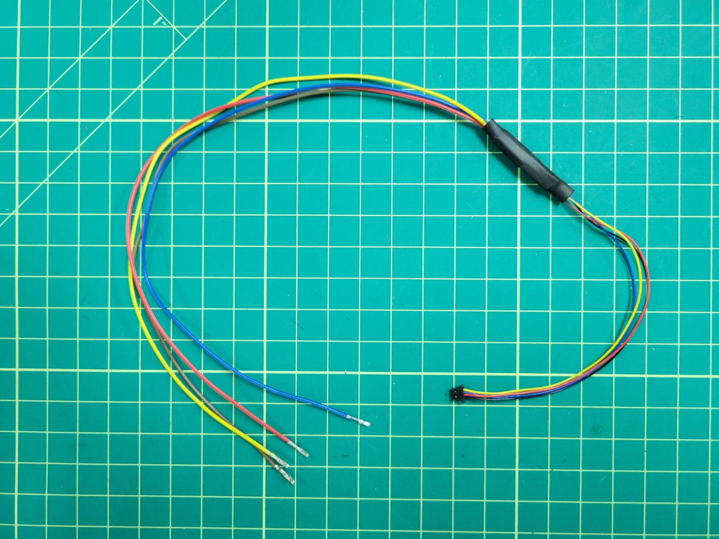
Thermal Camera Bundle
Attach the JST connector to the thermal camera and route the cables through the top accessory plate.
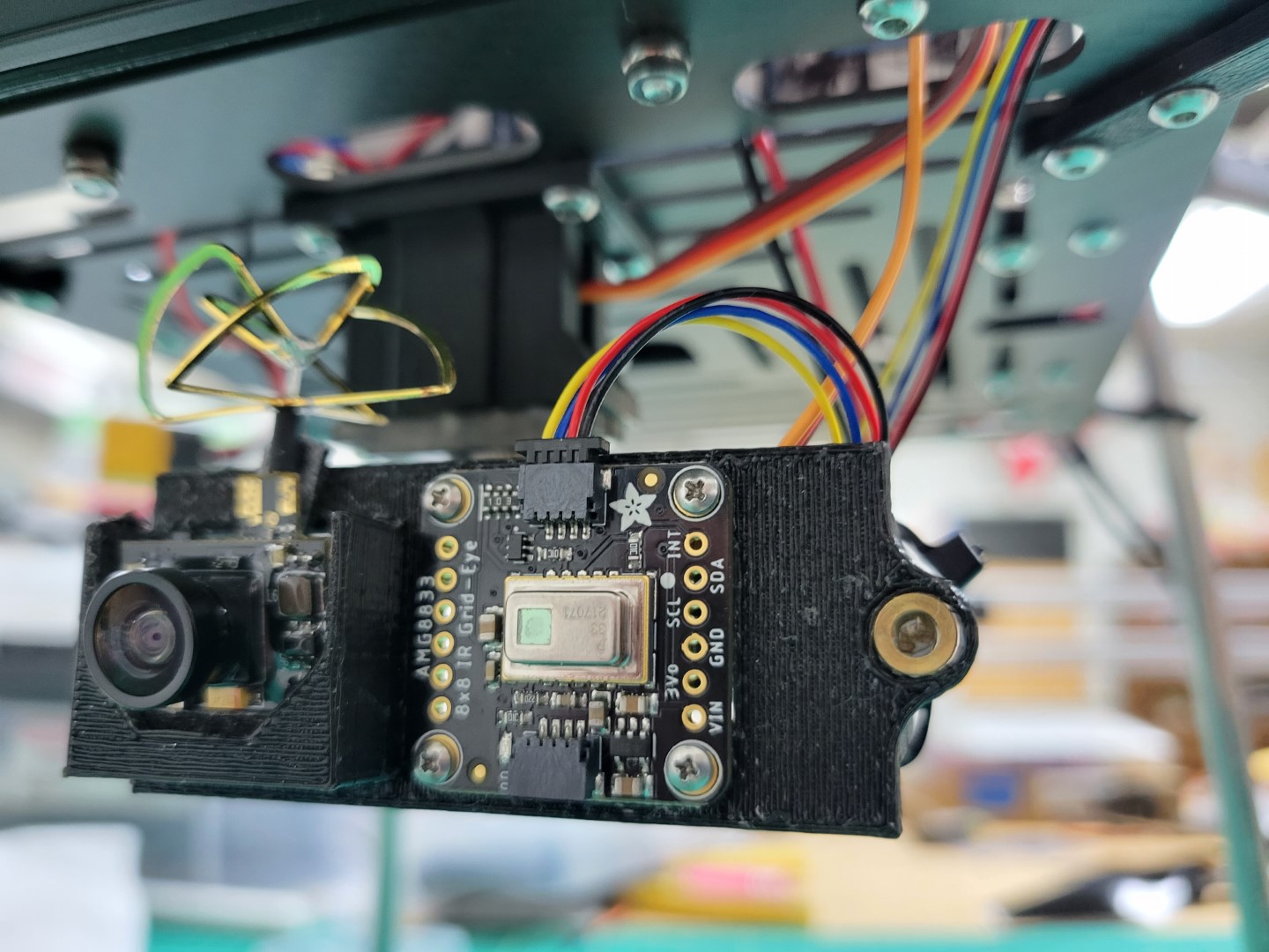
Thermal Camera Connection
Place your top cables into the 20x2 connector housing on your Jetson per the following wiring diagram.

Jetson Pinout
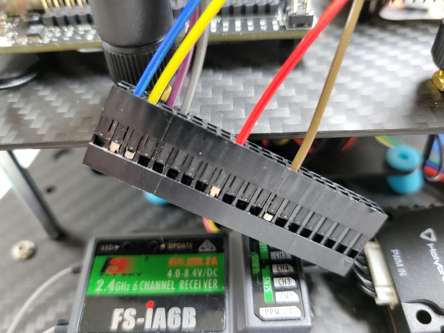
Thermal Camera 20x2 Connector
The final product should look like the following.
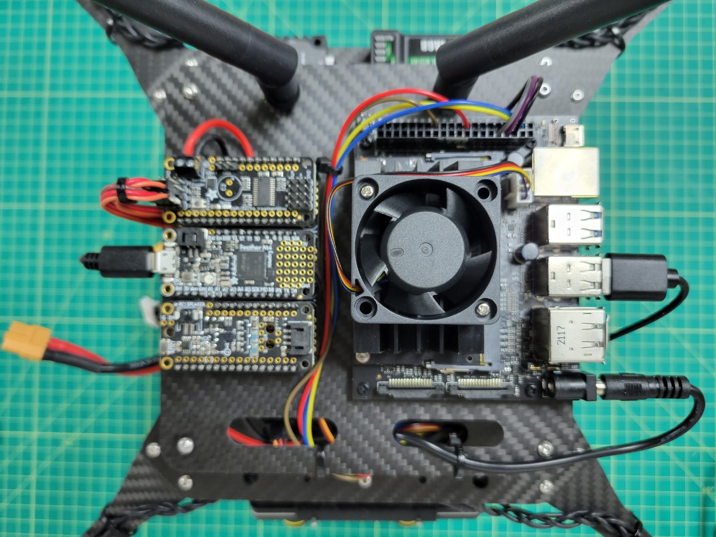
Thermal Camera Wiring Overview
15.2 - Gimbal Testing
Command used in video for starting the services
cd AVR-2022/VMC
./start.py run mqtt pcm thermal
15.3 - FPV Camera Testing
Overview
Your FPV camera has a built-in transmitter that will broadcast a video signal to the monitor, which has a built-in receiver. Open your FPV monitor box and pull out the components shown in the photo below.
Warning
Be sure to attach the both antennas to the FPV monitor before powering it. Otherwise you run the risk of burning out the receiver.
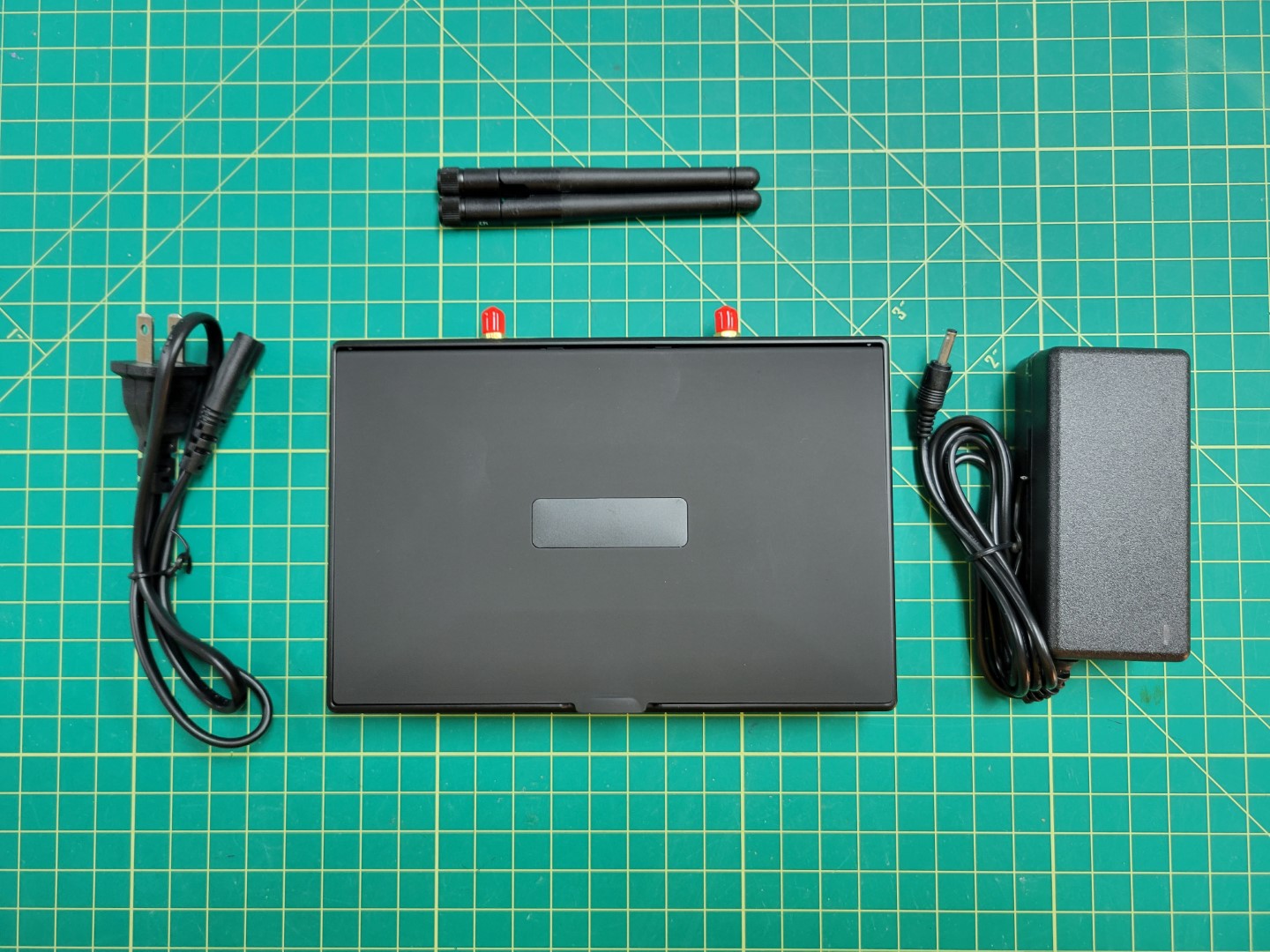
FPV monitor and built-in receiver
The video below will walk you through setting the band and channel of the transmitter and receiver.
Warning
The FPV transmitter gets VERY HOT. Be careful when setting the transmitter’s band and channel.
15.4 - CSI Camera
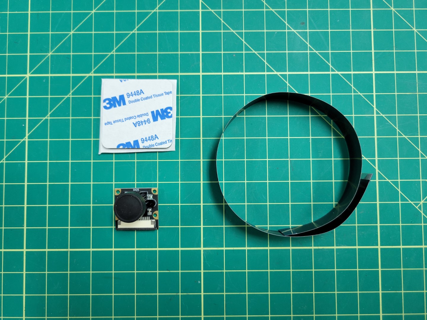
CSI camera and 300mm cable
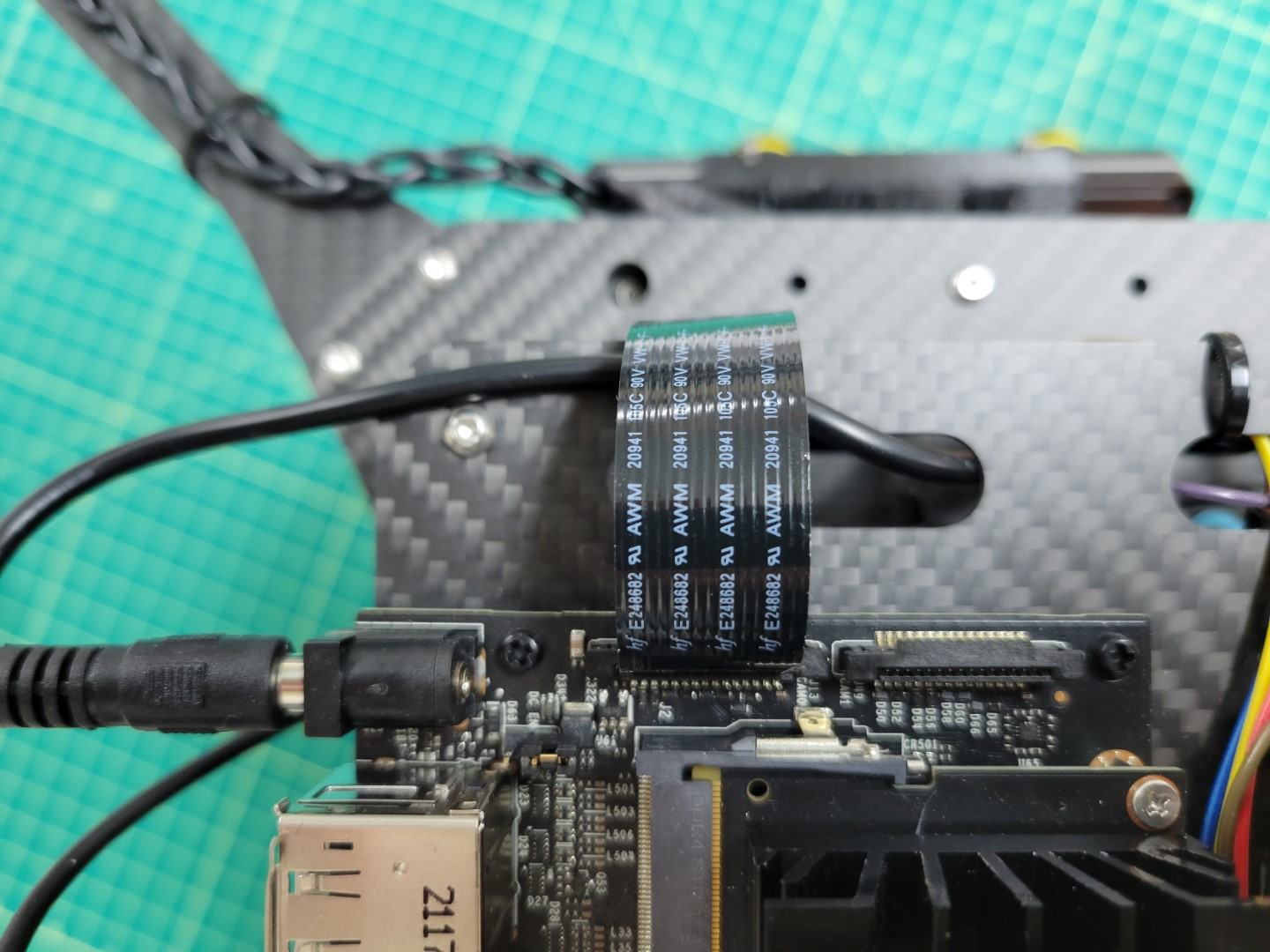
Cable attached to VMC
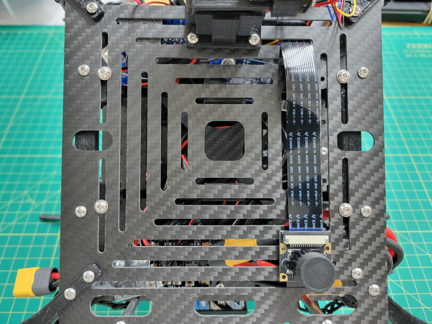
Cable attached to CSI camera
15.5 - LED Status Lights
The status lights are designed to provide an extra layer of quick and easy debugging to show the status of your drone at a glance.
To complete the status light installation you will need the following.
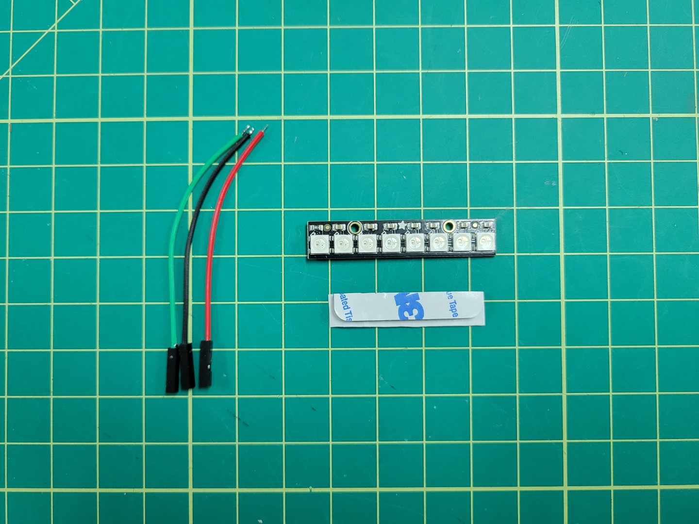
Components with wires cut to 3"
Wiring
Wire the green wire to DIN, red wire to 5VDC, and black wire to Ground. Remove the plastic housing from other end of the wires.
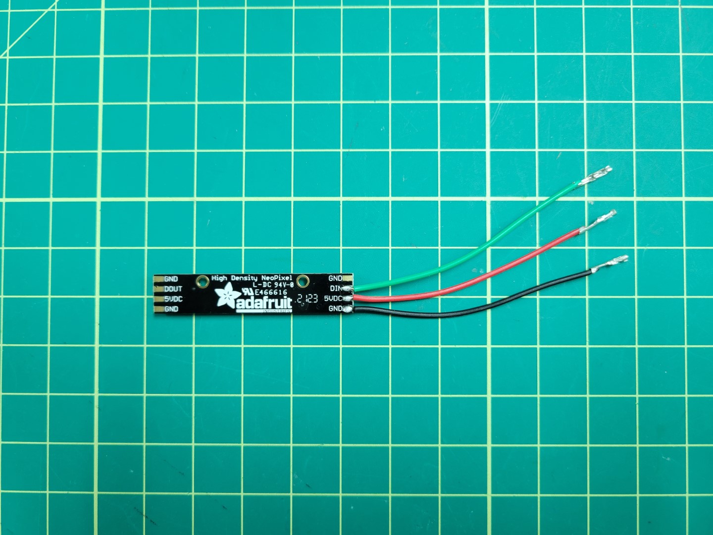
LED soldered and ready for VMC wiring
Insert wires into VMC housing per the following wiring diagram.

Jetson Header Wiring Diagram
This should result in the following.
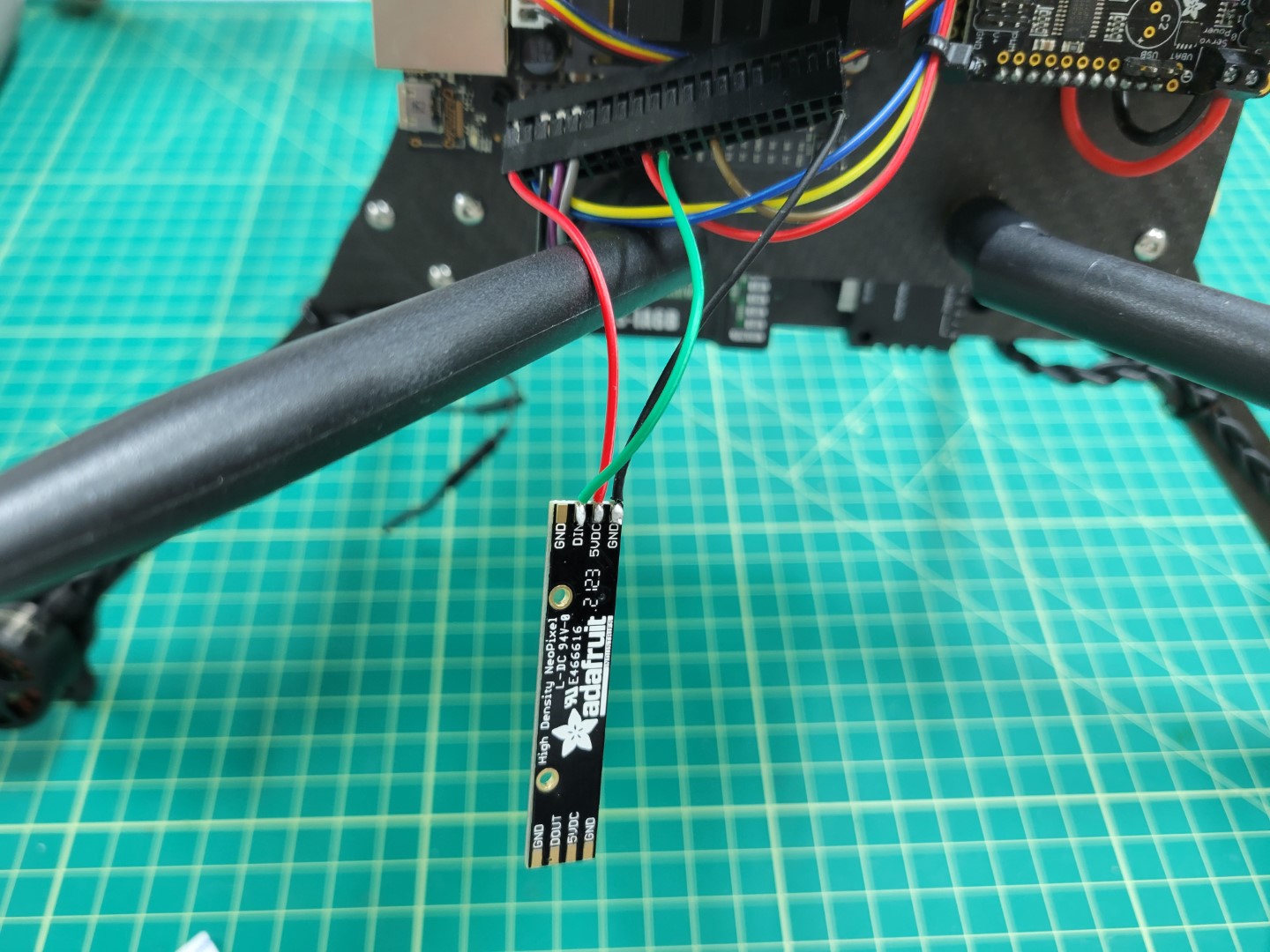
LED connected to VMC housing
Mounting
Use 3M double-sided foam tape to mount to the fan of the Jetson facing towards the rear of the drone.
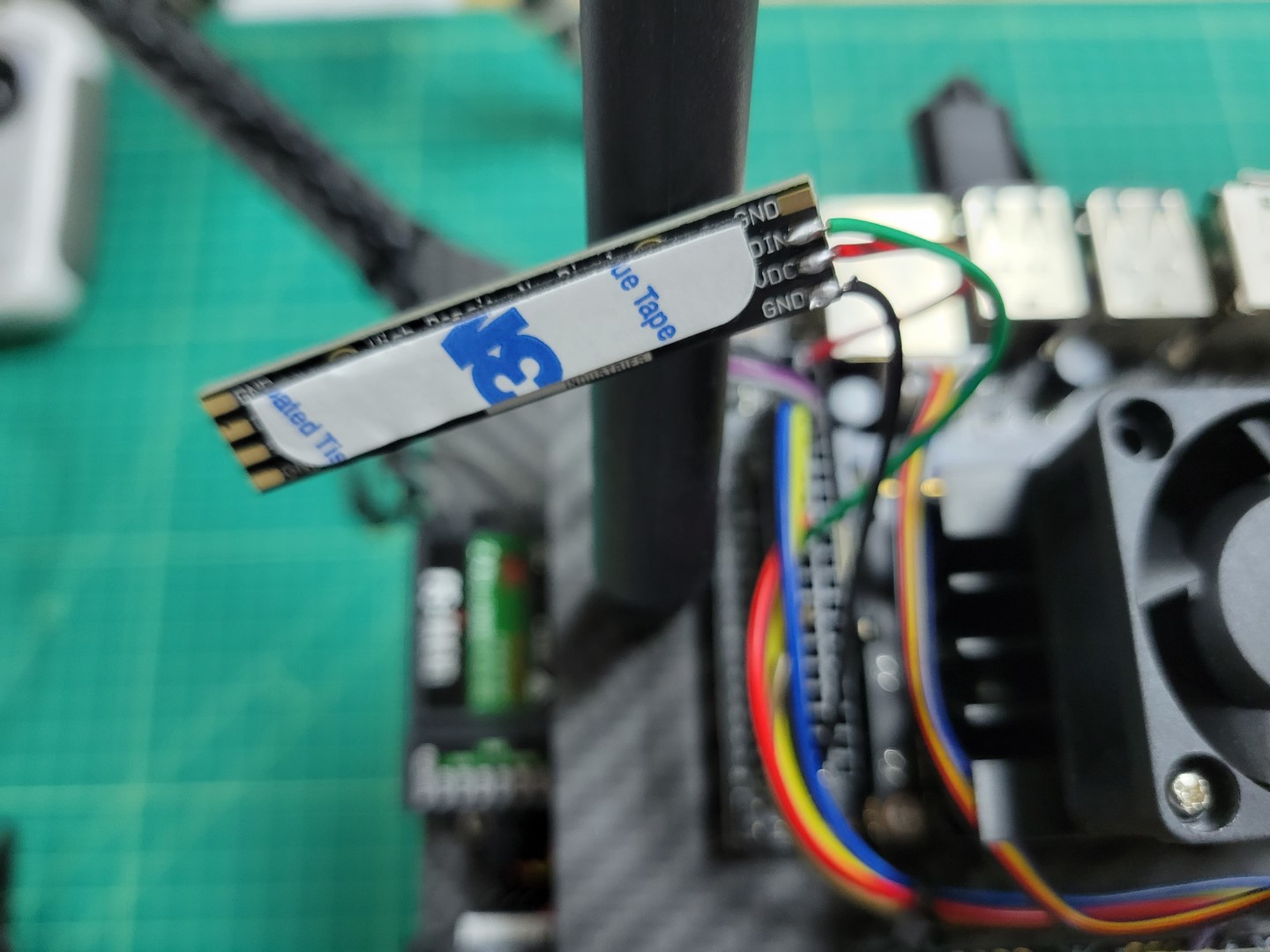
Adhesive for mounting LED
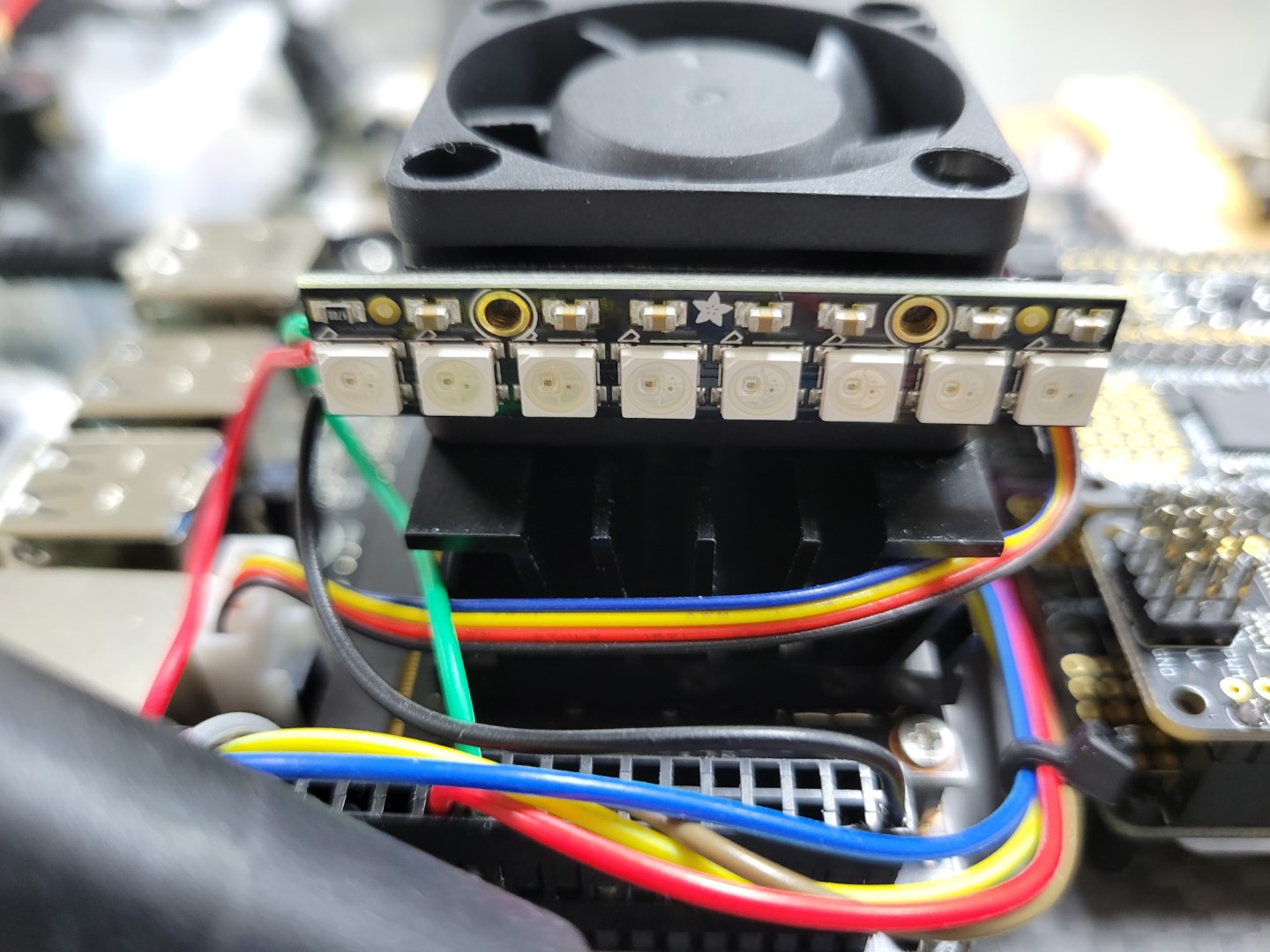
LED mounted on rear side of cooling fan
Testing
Commands run in video:
cd AVR-2022/VMC/
./start.py run -n
Feel free to explore and try different combinations for what you think is the most useful information.
For instance if you are doing just a flight test with no peripherals you may want to try the following.
cd AVR-2022/VMC/
./start.py run status -m
Light Definition
| Module: |
Message: |
LED: |
Color: |
| VIO: |
“avr/vio” |
1 |
PURPLE |
| PCM: |
“avr/pcm” |
2 |
AQUA |
| Thermal: |
“avr/thermal” |
3 |
BLUE |
| FCC: |
“avr/fcm” |
4 |
ORANGE |
| AprilTag: |
“avr/apriltags” |
5 |
YELLOW |
15.6 - LED Ring
In this section we cover how to install your LED light ring which will be used to communicate from the field back to teams.
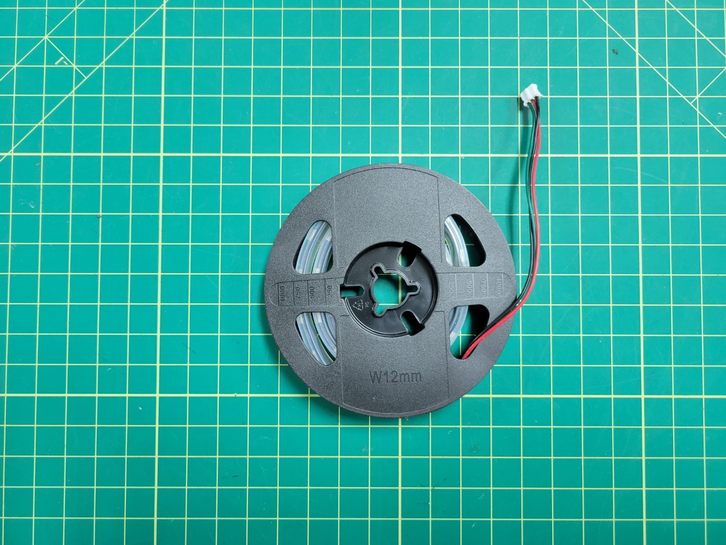
LED ring
Route your wire lead through the side slot on the top accessory plate and plug into the PCC as shown below.
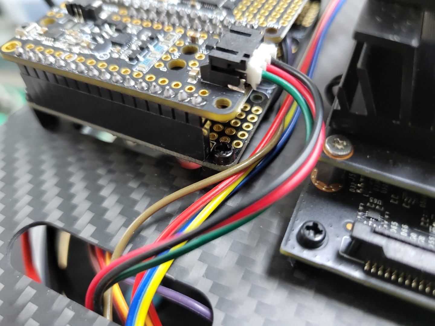
LED ring connected to PCC
Position the LED light ring under the top accessory plate around the inside of the standoffs and secure using zip ties.
Note
Feel free to find alternative means of attaching your LED rings, just ensure they are visible.
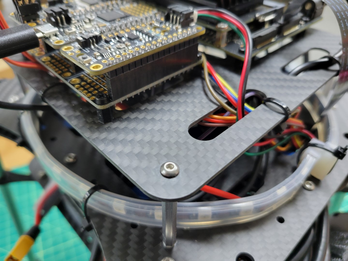
LED ring zip tied around top mid plate
Testing
16 - Sphero RVR
Your Bell AVR Competition team registration includes complimentary access to the Sphero
curriculum pages where they go into more detail about how to program and operate your
Sphero RVR.
RVR Introduction / Getting Started:
RVR Movement Intro Lesson:
RVR Color Sensor Intro Lesson:
17 - Autonomy and Beyond
Teams are encouraged to learn and practice programming with their drone. While it is
not mandatory, programming the drone to perform tasks autonomously will give you an
edge in the competition.
To gain an understanding of how autonomy works with the AVR drone please watch the video below.
Warning
Please make sure you know how to take manual control of your drone and update the home
location prior to launching your autonomous code.
Once you gain an understanding of how autonomy works through simulation you are ready to run your code on the real AVR drone. Make sure you pay attention to the following parameter:
MPC_XY_VEL_MAX
The default autonomous flight speed in PX4 is too fast for the AVR game court. You will need to slow it down. Our recommendation is something around 0.25 to 0.5 m/s, which is roughly 0.5 to 1 mph.
The example below demonstrates how we’ve set this param to 1 mph.
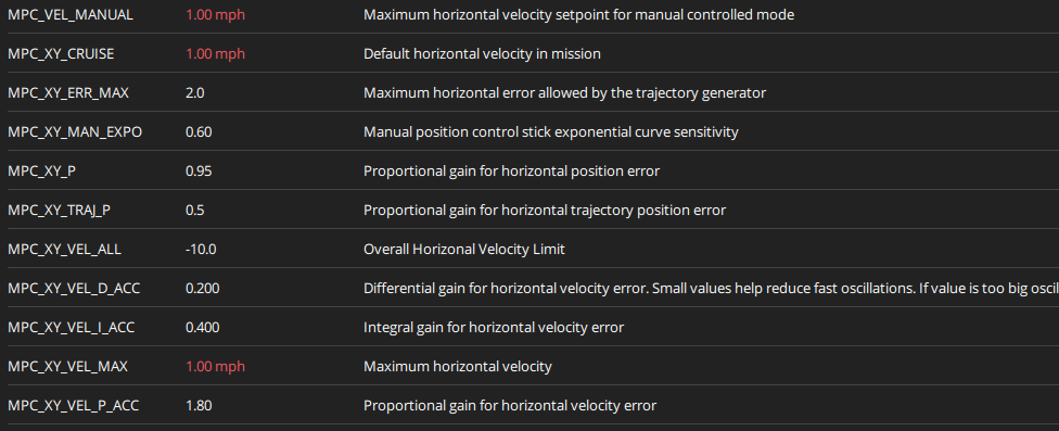
AVR drone right side view
Warning
Failure to lower the autonomy speed of your drone can lead to a crash and the need to rebuild your drone. Start slow and increase the MPC_XY_VEL_MAX param incrementally.
The following sections will help you with:
- Installing and using VS Code to manage your project
- Installing and using Python
- Installing and working with git
- Using the Bell AVR sandbox environment
- Building and running your code with Docker
17.1 - VS Code
VS Code is a popular open source code editor from Microsoft. It is just one of many IDEs (Integrated Development Environments) that can be used to write and test code. You will be using VS Code to build custom software for your drone.
VS Code can be downloaded and installed from the following Link: VS Code Install
Once VS Code is intalled, take some time to familiarize yourself with the user interface. An intro to the layout and basic feature of VS Code can be found here.
In the next step, we will get Python installed and test example scripts on your machine.
17.2 - Python
Python is a general purpose programing language. Being one of the most popular programming languages in the world, Python is known for readability and accessability. This section will walk you through installing Python and testing it on your machine.
VS Code Extension
Before we get started, make sure you have the Visual Studio Code extension for Python. Go to your extensions tab, search “Python”, and install.
Installing the Python Extension in VS Code
This extension allows for debugging, auto complete, and python environment managemebnt in VS Code.
Python Interpreter
An interpreter’s job is to take the high-level code written by your team in VS code and to translate it into machine language that is executed by your computer.
The Python interpreter is installed from Python.org - install it from here. Select the installer and run through the installation process.
To confirm your installation, open a command prompt window and execute the following command:
If your installation was successful, the output window will show the version of Python you have installed.
Setting Up a Project
Let’s set up a central location to store your future projects. Start by creating a “Projects” folder somewhere on your PC. Within this folder, make a “Hello World” folder. This is where we will create your first project.
In a blank VS Code window, open up this folder:
Opening a new folder from file
In your new workspace, create a new file called “hello.py”. The “.py” file format denotes a script written in python.
In this file, type the following:
Congrats, you’ve written your first python script! Before we run it, we will need to set up a python environment.
Setting Up a Python Environment
An “environment” is the context in which the python program runs. It consists of an interpreter and installed packages. We will be using “virtual environments”. These are are environments that are project specific and stored within the project itself. To create one in your “Hello World” project, start up a terminal.
Opening a new terminal in VS Code
In this terminal, type the following to create the virtual environment folder in your project:
To activate the environment:
The environment should now be activated. You’re now set up to run your script. In the terminal, type and execute:
If you were successful, you should see “Hello World” printed in the console.
17.3 - Git
In writing software for your drone, you will both need to interact with the sandbox environment as well as collaborate with your peers working on code from different machines. “Git” is built for tracking and managing changes between files. It is a staple of modern code management.
Windows Install
To install Git, simply select the standalone installer from the git-scm website
Run through the installation process. Once the install is completed, you will need to setup a username and email address for your machine.
Jetson Install
Git is already installed on your Jetson.
Git Configuration
Git needs to know who you are.
To set up a username and email address, open a terminal and type the following:
git config --global user.name "yourusername"
git config --global user.email "email@youremail.com"
Remember this email, because you will need to add it to your GitHub account later.
17.4 - GitHub
The AVR codebase is currently hosted on GitHub. Not to be confused with Git, GitHub is a cloud-based hosting service that lets you manage Git repositories. In order to customize the software on your drone, we ask you to create your own account, join an organization for your team, and host a version of that project in github
GitHub Account
To get started, follow this link and create an account. If you already have a GitHub account, you are free to use that.
Organizations
You’ll want to create a group where you can set access permission for your code to the rest of your team. In your profile settings, add an organization. If an organization has already been made, ask your team leader for access.
Forking a Repo
Bell engineers have created the base AVR repository here. If you’d like to make changes to this codebase in order to modify your drone, you will need to fork the repository.
A fork is a copy of a repository. You will be able to make changes to the code without modifying the Bell codebase. To fork the AVR codebase, click on the fork button on the top right of the AVR GitHub Repository. If someone on your team has already done this, ask them to share access with you.
Bell AVR GitHub Page
Take note of the url of the repository you just made.

URL of the new repository
We will need to change the upstream URL on your Jetson. Run the following commands:
git remote set-url origin https://github.com/your-username-here/AVR-2022
Your Jetson should now be configured for your forked Repo.
Syncing with the Bell Repository
If the Bell team makes changes to the main code repository, you will want to update your code fork to include those new changes. Updating your forked repo is simple in Github. Navigate to the main page of your repo, and select this “sync” option:
Fork Refresh
This option will allow you to see if your repository is behind. If it needs an update, simply select “Update branch” and sync the repository with your Jetson.
17.5 - Jetson Development
You should now be able to set up VS Code in order to modify code on your Jetson.
If you have not done this yet, familiarize yourself with using SSH to remote into your Jetson.
Take note of the username of your Jetson, and the host IP address.
Remote Development with VS Code
VS Code has extensions that allow you to develop from a remote machine. From your VS Code window, install the remote development extension, from Microsoft.
Remote Development Extension
Bring up the command pallette in VS Code by pressing Ctrl+Shift+P. Search “SSH” and select “SSH: Connect to Host”
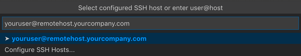
SSH Connect To Host
Type your username@IPaddress and press enter. Select “Linux” as your operating system. You may be prompted at several times to enter the password to your Jetson.
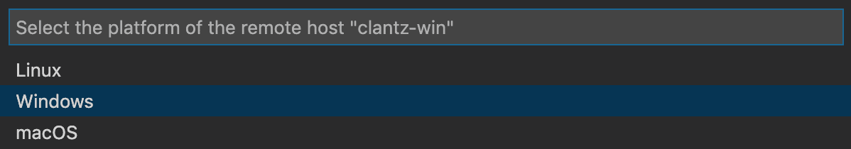
Operating System Selection
A seperate VS Code window should open. You now have access to the directories on your Jetson. On the left pane, select “Open Folder”.
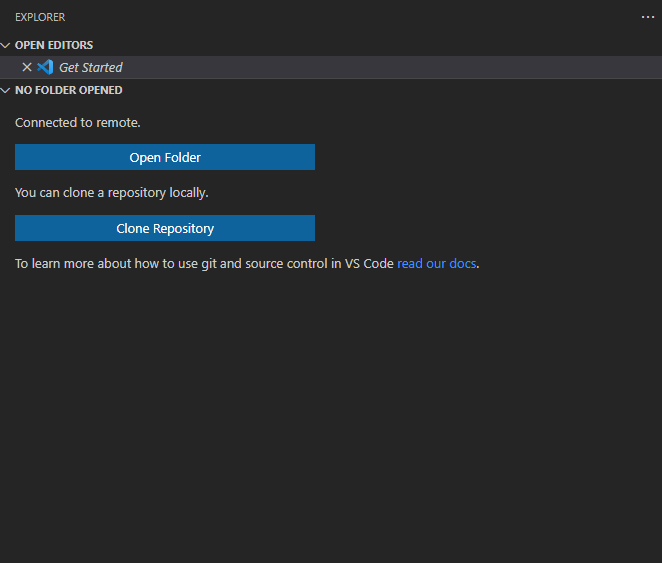
List of directories on the Jetson
When prompted, select the AVR-2022 location and press “OK”.
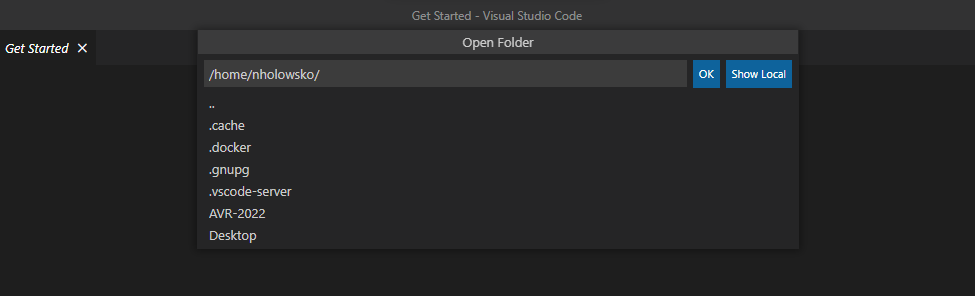
You should now be ready for development on your Jetson.
17.6 - Sandbox
Your team will need to create a sandbox environment to develop from.
In the
GitHub repository
we’ve provided an area for you to write
Python in order to accomplish your goals. The software stack for AVR is
made up of a series of modules, which are actually independent
Docker Containers.
Below is a graphic that shows the individual containers:
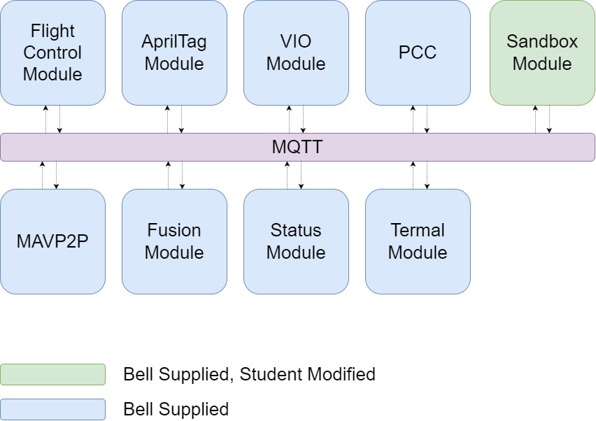
All of these modules communicate with each other over a message bus called
MQTT.
You could loosely think of MQTT like a social media feed.
You can publish posts and your friends can subscribe to your feed to see them.
Similarly, you can subscribe to your friends’ feeds and see their posts too.
Below is a non-exhaustive list of the kinds of data some of the modules publish:
- Flight Control Module
- Drone Position
- Drone Orientation
- Drone Velocity
- Drone Flight Mode
- Drone Battery Level
- AprilTag Module
- Visible AprilTag IDs
- AprilTag relative Positions
- VIO Module
- Zed Mini Position
- Zed Mini Velocity
- Zed Mini Confidence
- PCC Module
- Laser States
- Gimbal Control
- Fusion Module
- Coordinate Transformed Drone Position
- Thermal Module
- Status Module
You can read more about these modules here.
Your task here will be to subscribe to the
necessary topics above and write your own logic to produce the
desired output.
Using MQTT
You will be using the sandbox module to read from and interact with the other modules. By publishing messages to MQTT, you can create custom actions for your drone. The sandbox module has some example code to help you get started.
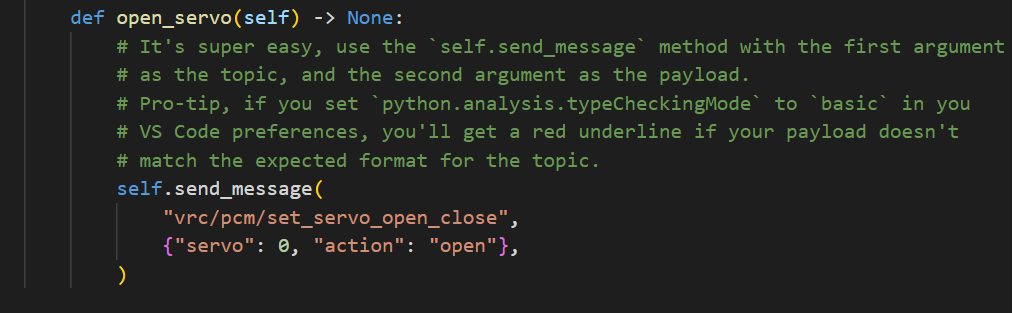
Example function that opens a servo
For full documentation of the MQTT topics and payloads available, go to
https://pypi.org/project/bell-avr-libraries/
and scroll down to “MQTT Documentation”.
17.7 - Using Git
This section will intorduce you to the basics of using git and will walk you through an example using VS Code.
Basics of Git
Git has a handful of basic commands that are useful to know. These can be executed from the command line, but we encourage you to use VS Code’s GUI as you get started.
We will primarily focus on commit, push, and pull.
-
A commit is used to capture the state of the project at a point in time. It saves any additions or changes to the local repository from your workspace.
-
A push adds all commited files to the remote repository. In this case, your remote repository is hosted in GitHub.
-
A pull gets files from the remote repository and puts them directly in your local directory. You will need to manually manage issues between conflicting files.
Example Git action diagram
VS Code Example
This will walk you through a Git command example using VS Code and the local repository on your Jetson. To start, make sure you have a VS Code window open with remote SSH access. Refer to previous steps for instructions on how to do this.
You should have an editor window on the left that looks like this:
Since you will be developing in the “sandbox” folder, we will experiment with that. Go ahead and add a new file. To do this, right click “sandbox” and “add new file”. Call it “test.txt”.
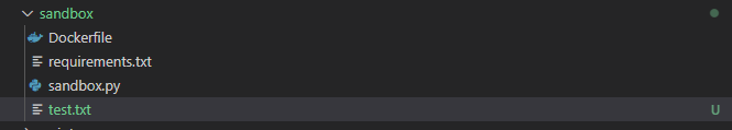
New test file in the sandbox directory
You’ve now made a change in your workspace, you can now commit it. Select the “Source Control” icon on the left pane of VS Code:
Source Control
The test file you made should show up in source control. Click the “+” button to commit the change. It will now be “staged”. In the upper text box, append a message to this commit describing the contents.:
Staged change with message
Click the check mark to commit the change. It is not saved in your local repository. The last step is to store this change in GitHub. The “Sync Changes” button that appears gives theuser the option to automatically pull and push to the remote repository. Select this to complete the process.
Pulling and Pushing your change
In the future, when working with others on your team, it may be necessary to manually manage conflicts when syncing changes.
17.8 - Docker
A Docker container is a lightweight executable package of a software that includes everything needed to run an application. In the AVR software package, parts of the code running on the Jetson(MQTT, AprilTag, Flight Control, etc.) are all run on individual Docker containers. You learned how to initialize and run them on the Jetson in the software section of this guide.
As a reminder, make sure to run the setup each time you want to pull the latest version of each of the modules.
cd ~/AVR-2022/VMC/scripts
git pull
./setup.py
To run the modules, use the start.py script.
cd ~/AVR-2022/VMC/
./start.py run
Your sandbox environment will be one of these modules. A basic sandbox.py script has been created for you. To run this specifically:
Each time you make changes/additions to your sandbox.py script, you will need to rebuild the module before running again.
Done!
Nice work. You’re now ready to start experimenting in the sandbox module!
18 - Diving Deeper
18.1 - Glossary
4S LiPo
4S LiPo refers to a Lithium Polymer battery that has 4 cells wired in series,
which means it has a fully charged capacity of 16.8V.
More info here.
CW/CCW (Clockwise/Counterclockwise)
CW stands for Clockwise and CCW stands for Counterclockwise.
This refers to the direction a motor or propeller is meant to spin.
A CCW propeller on a CW motor will produce lift in the wrong direction,
so make sure to always double-check!
Electronic Speed Controller (ESC)
An Electronic Speed Controller controls how fast a motor spins.
It receives a desired speed set-point from the Flight Controller and
adjusts the power going to the motor to match the requested speed.
More info on how they work here.
Flight Controller (FC) or Flight Control Computer (FCC) or Flight Management Unit (FMU)
The Flight Controller can go by many names, but in practical terms, it just a
small computer that has sensors for determining the position and orientation of
the drone, along with circuitry for controlling motors based on input from a pilot
or autopilot. The flight controller used for the AVR
(NXP RDDRONE-FMUK66)
is running the PX4 flight stack, which provides basic functionality you’d expect
from a hobby drone, and even some autonomy functions.
Ground Control Station (GCS)
A ground control station is an operator station from which your drone
is controlled from. In our case, this will be a laptop running QGroundControl.
More info here.
M3 Screw
An M3 screw is a metric screw with a 3mm diameter.
This type of screw is used to build the entire X4 500 frame.
More info here.
MAVLink (Micro Air Vehicle Link)
MAVLink is a standard protocol to send messages between a ground control station
and an unmanned vehicle and vice versa. These messages include important information
such as velocity, attitude, battery state, waypoints, etc.
More info here.
MAVLink Router/MAVP2P
MAVLink Router and MAVP2P are both pieces of software that help to connect multiple
MAVLink devices together. A standard MAVLink setup has a ground control station
communicating directly with an unmanned vehicle, but these pieces of software allow
you to connect a single ground control station to multiple vehicles or vice versa.
More info here for MAVLink Router
or here for MAVP2P.
Peripheral Control Computer (PCC)
The Peripheral Control Computer is a microcontroller running custom software that
accepts requests from things like your laptop or, later on, the VMC to control
servos and LEDs that are attached to it.
Power Distribution Board (PDB)
A Power Distribution Board is connected to your battery and takes the power coming
from the battery and distributes it to the various components on your drone at the
voltages and currents that they expect.
More info here.
PX4
PX4 is an open-source autopilot software stack. This contains low-level algorithms
running on the flight controller that constantly interpret things like position,
attitude, altitude, heading, etc. and adjust the motors to keep your drone on
course and can manipulate the drone to fly to desired positions.
More info on PX4 here.
QGroundControl (QGC)
QGroundControl is ground-control software for drones and other unmanned vehicles.
It allows you to easily connect to a drone and give it commands such as to takeoff,
land, and uploading missions to it for it to perform.
More info here.
R/C Controller
An R/C (radio-controlled) Controller can be used with QGroundControl to manually
fly your drone while not in autonomous mode.
More info here.
Vehicle Management Computer (VMC)
The Vehicle Management Computer is the companion computer that performs various
tasks and communicates with the Flight Controller. This is where your custom software
will be run to complete the challenges for the competiton.
Advanced Vertical Robotics (AVR)
The Advanced Vertical Robotics competition is a robotics competition put on by Bell Flight
to challenge high school students to develop STEM skills outside of the classroom
and work together to solve engineering challenges in a fun robotics competition
in the vertical dimension.
X4 500
The X4 500 is the frame of your drone. This is what all of the components will
be mounted to.
More info here.
18.2 - Architecture
General
The software for AVR is designed around a pub/sub messaging system in order to exchange
data throughout the system. This allows software modules to operate independently
of each other, and to communicate with each other over a network.
A pub/sub messaging system is a system which allows clients to publish
data to “topics” and clients can subscribe to incoming messages on defined topics.
Think of how email works for example. You sending an email to someone is like
publishing data to a topic (their email address), and you subscribe to all messages
on a topic (your email address). However, a pub/sub system allows multiple clients
to subscribe to the same topic.
With that in mind, the core principles of AVR software architecture are as follows:
- Data exchange must happen through the MQTT broker.
- All MQTT data must be JSON encoded.
- All modules are run as containers.
Because of all of the hardware components of AVR (PCC, FCC, thermal camera, etc.),
what this generally means is that each module acts as a hardware to MQTT adapter.
For example, the FCM module publishes telemetry data over MQTT, and feeds
fake GPS data from MQTT to the FCC.
This modular, open system makes it simple to add new modules or functionality
to AVR. The GUI for example,
is 100% based on consuming MQTT data.
Modules
Here is a description of the modules in AVR and what they all do.
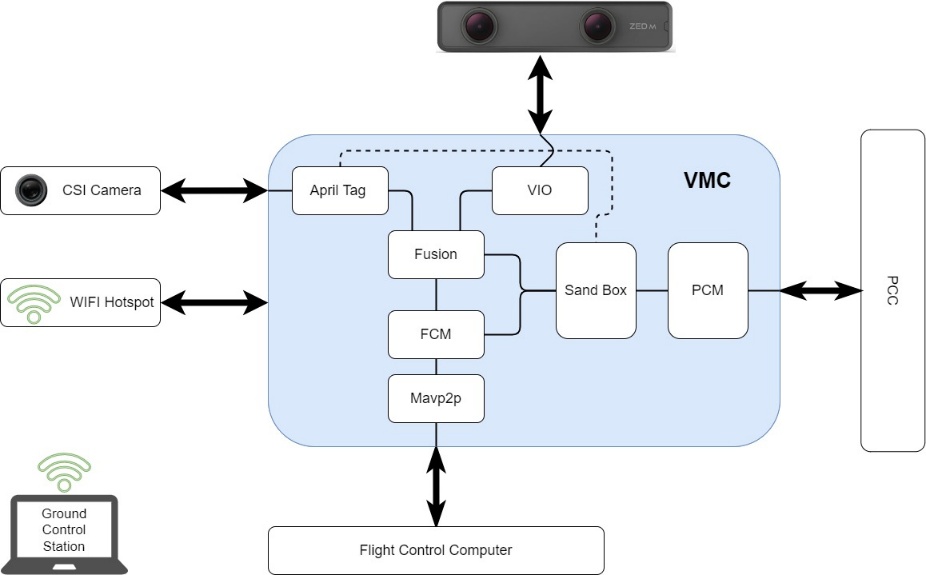
Module Flowchart
AprilTag
Source Code
The AprilTag module is responsible for using the images pulled from the CSI
camera to scan for visible AprilTags.
A low-level C++ program captures the images and hands them off to the Jetson’s GPU
for processing and publishes the raw detections to the “avr/apriltags/raw” topic.
From here, a second Python program inside the module subscribes to this topic,
and upon new detections, uses linear algebra to perform a coordinate
transformation in order to get several pieces of data.
These detections include the tags ID, as well as the drone’s absolute location
in the court (pos_world), and the drones relative location to the tag itself (pos_rel).
This data is then broadcast out over MQTT for other modules, such as the
Fusion and Sandbox modules to consume.
This is the only module with C++ code, for performance reasons.
Flight Control
Source Code
The Flight Control module (FCM) is responsible for communicating with the
FCC over MAVLink. This module takes telemetry data from the FCC and publishes
it over MQTT. Additionally, it takes fake GPS data from the Fusion module
and feeds it to the FCC.
There also exists functionality to send commands to the FCC, such as arming the drone,
or sending it missions, but this is disabled due to the drone’s current lack of
knowledge of where it is in global coordinates.
Fusion
Source Code
The Fusion module is responsible for fusing multiple data sources
to produce the final fake GPS data that is fed to the FCC. Currently, this only takes
data from the VIO module, but experimental functionality exists to also take data from
the AprilTag module to position itself more accurately in global coordinates.
This is the only module which is pure Python and has no hardware component.
Mavp2p
Source Code
The Mavp2p module is responsible for bridging multiple MAVLink connections
together. This is just a Docker container for the amazing open-source project
mavp2p.
MQTT
Source Code
The MQTT module is responsible for running the MQTT broker. This is
a thin wrapper around the
docker.io/library/eclipse-mosquitto
container with a configuration baked in.
The port 18330 is used instead of the normal 1883 port because it puts it
outside of the normal operating system privileged port range.
Peripheral Control
Source Code
The Peripheral Control module is responsible for communicating with the
PCC over serial. This is a thin MQTT to serial bridge.
Status
Source Code
The Status module is responsible for consuming status information from the various
other modules and updating the status LEDs connected to the VMC. This also
communicates some with the host Jetson as well to check if it’s being power-limited.
Thermal
Source Code
The Thermal module is responsible for capturing thermal images from the thermal camera
and publishing them over MQTT.
Visual Inertial Orientation
Source Code
The Visual Inertial Orientation (VIO) module is responsible for
capturing data from the stereoscopic tracking camera, and converting it into
global-ish coordinates.
This module considers wherever it is started as “0,0,0” and thus the drone’s movements
are relative to that. Because PX4 only thinks in global coordinates, this module
then uses a hardcoded latitude and longitude to convert the data into
global coordinates. They’re not true global coordinates, however,
as they’re still relative to where it was started.
This module is the core of the AVR “secret sauce” to enable GPS-denied stabilized
flight.
18.3 - Control Loops
Control Loops
When a drone flies, there are many things going on at once,
some of them are happening much more quickly than others. We can break these down as
inner-loops and outer-loops.
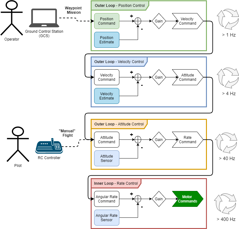
Rate Control
This is the inner-most loop, running several hundred times per second usually.
The purpose of this loop is to control the angular rate of the vehicle, that is,
how quickly the vehicle is pitching forward or back, rolling to the left or right,
or yawing to change its heading. If we can successfully control the angular rate
of the vehicle, it is said that we are able to stabilize the vehicle.
All other control loops are considered outer loops because they depend on this
inner loop providing a stable vehicle.
Rate control is achieved by comparing a sensor value for the angular rate of the
vehicle in each axis to a set point, or target, value. Once we have the knowledge
of how far our state (pitch rate / roll rate / yaw rate) is away from where we
want it to be, we can apply some gain factor (we can tune these gains to change
the performance of the controller) to that difference, and we send those values
to the motor controllers as motor commands. All control loops in our drone work
on this principle.
Attitude Control
The Attitude control loop is the first outer loop, as its name suggests,
this control loop allows us to command the vehicle to a particular attitude.
If we wanted to hover, for instance, we would send attitude commands of 0 degrees,
for the pitch and roll axis. It’s important to note that the output of the
attitude controller is the input of the rate controller, they are effectively
nested control loops. It is important to note the difference in frequency that
these loops operate at; typically, an attitude loop is about an order of
magnitude slower (or a division by 10) than the rate control loop.
Velocity Control
Similarly, the velocity controller compares velocity commands
(usually in the form of forward velocity and vertical velocity) to a
velocity estimate that has been calculated, applies some controller gain,
and then computes what the desired vehicle attitude is to achieve that velocity,
passing that desired attitude to the more inner loop below.
Position Control
Surely, you see where this is going. Once we can control the velocity of the vehicle,
we are able to control the position of the vehicle, because velocity is merely
the derivative of position, right? That is essentially true, however, we always
need to keep in mind the different coordinate systems the vehicle is operating in.
Almost exclusively, the coordinate frame that angular rates and attitudes are
measured in is not relevant for position control, usually we want to command the
vehicle to a particular latitude and longitude. How do you define a vehicle’s roll
attitude in the coordinate system that latitude and longitude make sense in?
There will be a coordinate transform between what position command is being set
by the operator and how the vehicle interprets that before it can apply the controller.
For position control to work, the vehicle must have an estimate of
where it is in space. This is where the VMC comes in, as we’ve mentioned,
we are flying indoors and don’t have GPS to use a sensor, so we must find out
the drone’s position with other sensors. The VMC uses two different sensors
together to estimate the position of the vehicle in the inertial frame that is
flying arena, that is, this frame is not moving, it is the reference for all
other frames. Estimating position indoors is very challenging, and a great deal
of work has been done to simplify the operation for these drones, it takes a
lot of calculation and code to interface with the position sensors and generate
these estimates, that’s why we have to do this work on the VMC and not the FC,
the VMC is a much more powerful computer. Luckily for us, the position control
loop is the slowest of the control loops, so we only have to send the position
feedback to the more inner loop controls a few times a second.
19 - Troubleshooting
This section provides instructions on Troubleshooting different things of your drone
The following are some common issues that have been seen in the past.
For items not listed in the following sections please check the forum for existing
answers or submit a new question.
19.1 - VMC
The following are some common issues that have been seen in the past.
In the rare instance that things get really bad, you may need to reflash your jetson.
Should this be the case, the next few sections will guide you through this proccess.
19.1.1 - System Setup
Your Jetson should already have the operating system installed and configured for you.
These instructions are provided in case you need to wipe your Jetson and start fresh.
Initial Setup
Note
If using a serial connection, all the navigation here on out will be done via your
keyboard. Use the arrow keys and Tab to move the cursor,
and Enter to confirm options.
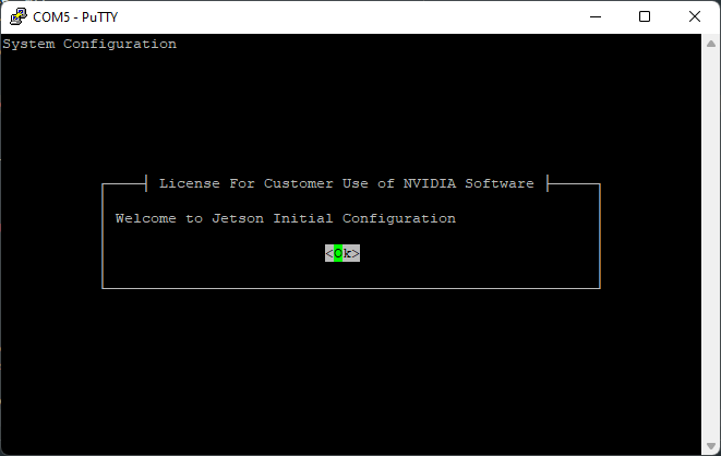
Select “Ok”
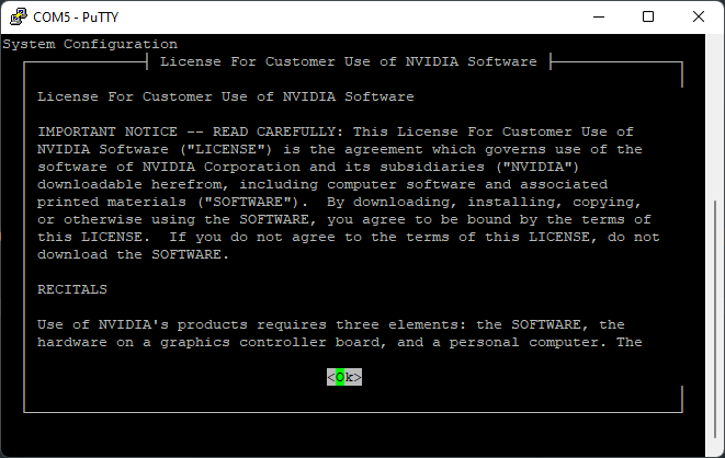
Scroll through agreement and select “Ok”
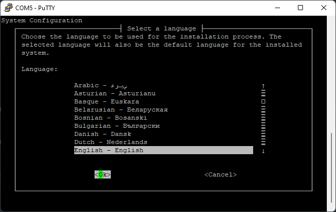
Select your language

Select your country
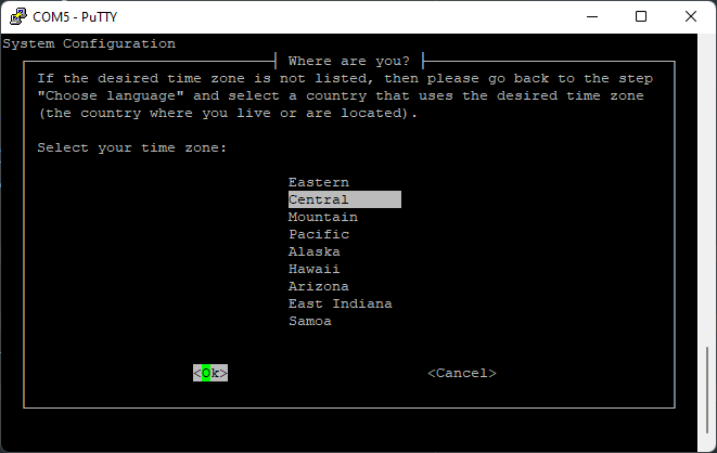
Select your timezone
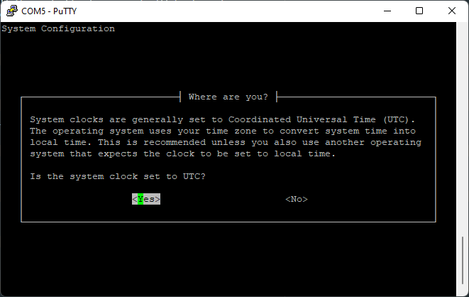
Allow clock to be set to UTC
Creating your account
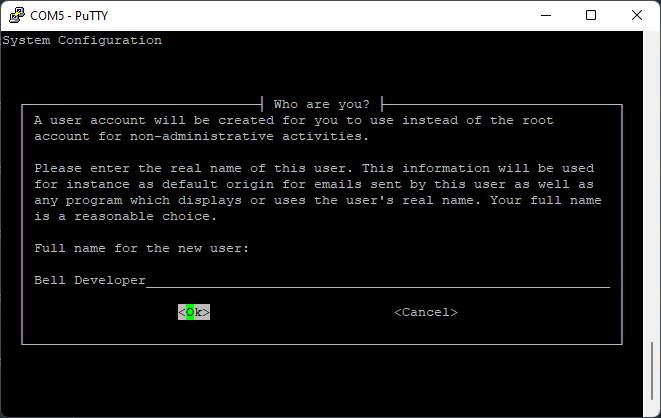
Enter a name, such as your school’s name
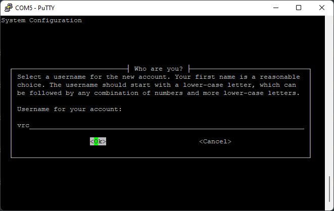
Choose a username, such as “avr”
Choose a password
Retype your chosen password
When asked about resizing the partition, leave the default.
Network Configuration
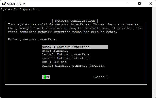
Setting up a network connection is not needed at this time. To bypass this, select
“dummy0” and let the autoconfiguration fail.
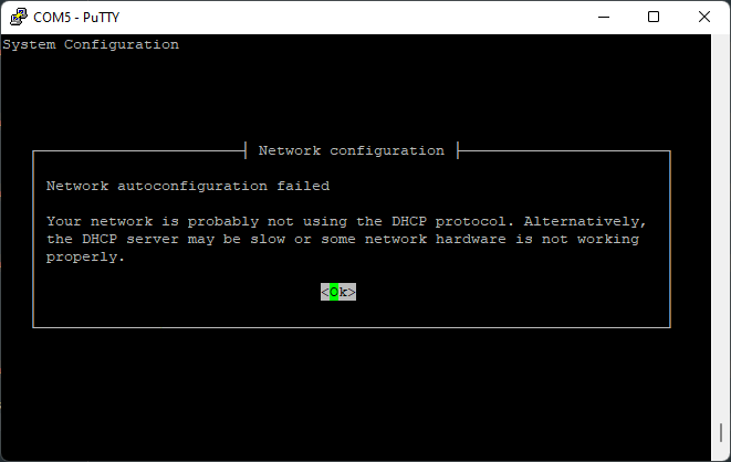
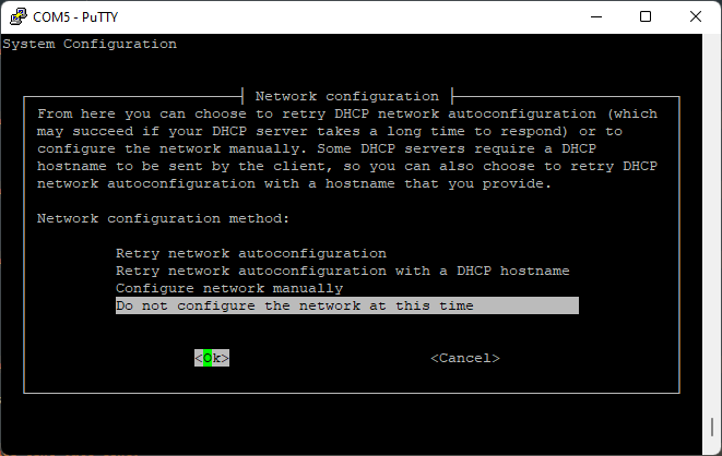
Go ahead and select “Do not configure the network at this time”.
Final Setup
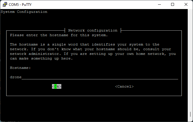
Select an appropriate hostname for your Jetson.
“drone” is a good choice.
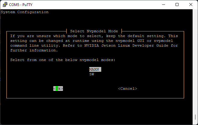
Choose the “MAXN” power mode.
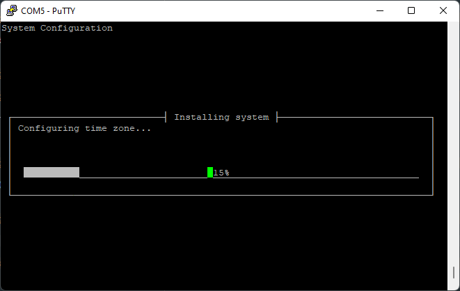
Let the installation finish. Once it’s done, reboot your Jetson.
19.1.2 - Installing VMC Software
Internet
In order to install the AVR software, your Jetson needs to have an internet connection.
The easiest way by far is if you have ethernet available. If so, just plug
an ethernet cable into your Jetson and you should be good to go.
If you don’t have ethernet, you can use a WiFi connection. First, you can list
the available networks with:
Example:
WiFi network list
Hit q to exit the list.
If the Jetson is already connected to a WiFi network, you can disconnect it with:
sudo nmcli device disconnect wlan0
To connect to a WiFi network, run:
# with a password
sudo nmcli device wifi connect <network name> password <password>

# without a password
sudo nmcli device wifi connect <network name>
such as:
sudo nmcli device wifi connect "WI do drones FI" password "Flying_Is_Fun"
If your network name or password has a space or other special characters,
you’ll need to wrap it in quotes as shown above.
Install
git clone --recurse-submodules https://github.com/bellflight/AVR-2022 ~/AVR-2022
cd ~/AVR-2022/VMC/scripts
chmod +x setup.py
./setup.py
This clones the software repo, changes directory into the repo you
just cloned, makes the setup script executable,
and then executes the setup script.
Setup script starting
This setup script will automatically install and configure
everything needed on your Jetson to get it ready for competition.
This script does do operating system updates, so depending on your
internet connection, it may take a while to run.
At the end of the setup script, it will perform a few self-tests
to make sure everything is configured properly.
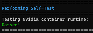
Self-tests passing
Once this is done, please restart your Jetson. Some system settings were changed
that require a reboot to take effect.
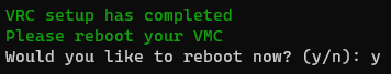
Reboot prompt
After this, you should be ok to continue on with the setup per the updating per
Updating VMC Software